Przewodnik po technologii czujników CMOS: zastosowania przemysłowe, systemy wizyjne i integracja termowizyjnej AI
17 sierpnia 2026
Cyfrowe rdzenie kamer termowizyjnych a analogowe: Przewodnik po rozwiązaniach AI OEM nowej generacji
18 sierpnia 2026
Analogowe moduły kamer termowizyjnych: Wysokoprecyzyjne rdzenie termiczne CVBS i AI do integracji przemysłowej
W krytycznej automatyce przemysłowej, bezzałogowych systemach powietrznych (UAS), robotyce terenowej i telemetrii obronnej potrzebujesz wizualnego sprzężenia zwrotnego, które nie zacina się ani nie dławi. Podczas gdy nowoczesne cyfrowe protokoły strumieniowania, takie jak RTSP przez Ethernet, USB Video Class (UVC) i bezpośredni MIPI-CSI2, dominują w systemach wbudowanych o dużym obciążeniu obliczeniowym, analogowe moduły kamer termowizyjnych pozostają niekwestionowanym koniem roboczym dla deterministycznych, bezopóźnieniowych torów wideo. Wyprowadzając czysty kompozytowy sygnał wideo w paśmie podstawowym (CVBS/NTSC/PAL), analogowy rdzeń termiczny łączy fizykę czujników długofalowej podczerwieni (LWIR) bezpośrednio z ciągłymi, nieskompresowanymi analogowymi liniami wideo na długich odcinkach kabli koncentrycznych, nadajnikach RF i pierścieniach ślizgowych. To całkowicie omija obciążenie systemu operacyjnego, artefakty kompresji, buforowanie klatek i przerwy spowodowane utratą pakietów, które nękają cyfrowe stosy sieciowe.
Oto sedno: nowoczesne projektowanie elektrooptyczne nie zmusza już do wyboru między niezawodnością analogową a nowoczesnymi obliczeniami brzegowymi. Rdzenie kamer termowizyjnych nowej generacji działają w architekturach hybrydowych. Mówimy o wysokorozdzielczych matrycach mikrobolometrycznych z tlenku wanadu (VOx) — do rozdzielczości 640×512 przy ciasnym rastrze pikseli 12 μm — połączonych z dedykowanymi sprzętowymi procesorami sygnałowymi (DSP). Te rdzenie wyprowadzają analogowy sygnał CVBS bezpośrednio do monitora polowego pilota lub analogowego łącza bezprzewodowego, jednocześnie przesyłając nieskompresowane klatki cyfrowe (przez MIPI-CSI2 lub USB) do akceleratora AI na brzegu sieci w celu komputerowego widzenia w czasie rzeczywistym, radiometrycznego śledzenia termicznego i wielospektralnej fuzji czujników.
Ten przewodnik techniczny omawia podstawową fizykę, kompromisy interfejsów, parametry projektowania optycznego, praktyki inżynierii elektrycznej na poziomie PCB oraz rzeczywiste plany integracji wymagane do uruchomienia przemysłowych analogowych modułów termowizyjnych w wymagających warunkach terenowych.

Spis treści
- 👉 Zrozumienie analogowego wideo termicznego: fizyka, przetwarzanie sygnałów i architektura CVBS
- 👉 Analogowe a cyfrowe interfejsy termiczne: opóźnienia, transmisja i obciążenie sprzętowe
- 👉 Kluczowe specyfikacje inżynieryjne: rastr czujnika, NETD i optyka
- 👉 Porównanie produktów przemysłowych: seria MD i miniaturowe rdzenie LWIR
- 👉 Podręcznik integracji elektrycznej i sprzętowej: zasilanie, impedancja i mostkowanie wielu magistral
- 👉 Profile zastosowań przemysłowych i lotniczych o wysokiej niezawodności
- 👉 Często zadawane pytania (FAQ)
Zrozumienie analogowego wideo termicznego: fizyka, przetwarzanie sygnałów i architektura CVBS
Obrazowanie termiczne polega na przechwytywaniu promieniowania elektromagnetycznego w paśmie długofalowej podczerwieni (LWIR), zazwyczaj między 8 μm a 14 μm. Ta dziedzina podlega prawu promieniowania Plancka i prawu Stefana-Boltzmanna ($E = \epsilon \sigma T^4$), zgodnie z którymi każdy obiekt o temperaturze powyżej zera absolutnego emituje promieniowanie proporcjonalne do swojej emisyjności i czwartej potęgi swojej temperatury bezwzględnej. Przekształcenie tych subtelnych zmian fotonów w standardowy kompozytowy sygnał wideo wymaga ściśle zarządzanej ścieżki sygnału elektrooptycznego.
Łańcuch sygnałowy zaczyna się od elementu przedniego. Padające promieniowanie LWIR przechodzi przez zespół soczewek germanowych z powłoką antyrefleksyjną i trafia na matrycę ogniskową (FPA). W wysokowydajnych rdzeniach matryca ta jest zbudowana z niechłodzonych mikrobolometrów z tlenku wanadu (VOx). Jak szczegółowo opisano w standardowej literaturze inżynieryjnej dotyczącej obrazowania termicznego i termografii, każdy piksel składa się z mikroskopijnej struktury mostkowej zawieszonej nad podłożem krzemowym. Gdy fotony podczerwieni uderzają w mostek, jego temperatura wzrasta, zmieniając rezystancję elektryczną materiału na podstawie jego temperaturowego współczynnika rezystancji (TCR).
Bezpośrednio pod matrycą mikrobolometrów układ odczytu (ROIC) przykłada ultrastabilne napięcie polaryzacji, odczytując niewielkie zmiany rezystancji wiersz po wierszu i kolumna po kolumnie za pomocą pojemnościowych wzmacniaczy transimpedancyjnych. Te sygnały analogowe są natychmiast przekształcane na surowe wartości cyfrowe przy użyciu szybkich 14-bitowych lub 16-bitowych przetworników analogowo-cyfrowych (ADC). Przetwarzanie surowych danych bolometrycznych w domenie cyfrowej ma kluczowe znaczenie, ponieważ surowe czujniki termiczne charakteryzują się nieodłącznymi różnicami między pikselami, które w przeciwnym razie zniszczyłyby obraz.
Wewnątrz modułu DSP lub FPGA surowy 14-bitowy strumień przechodzi przez wyspecjalizowany potok przetwarzania obrazu w czasie rzeczywistym:
- ⚙️ Korekcja niejednorodności (NUC): Normalizuje różnice odpowiedzi pikseli i eliminuje dryft termiczny przy użyciu fabrycznych tabel wzmocnienia połączonych z aktualizacjami kalibracji z mechaniczną migawką lub bez migawki.
- ⚙️ Ukrywanie wadliwych pikseli (DPC): Wykrywa nieodpowiadające lub zaszumione piksele w locie i zastępuje je czystymi wartościami interpolowanymi obliczonymi z sąsiednich pikseli.
- ⚙️ Cyfrowe Wzmocnienie Detali (DDE): Stosuje górnoprzepustowe filtry przestrzenne, aby wydobyć drobne tekstury powierzchni i krawędzie mechaniczne bez wzmacniania szumu tła czujnika.
- ⚙️ Kompresja zakresu dynamicznego (DRC) i adaptacyjna AGC: Kompresuje ogromny 14-bitowy zakres dynamiczny termiczny do czystej 8-bitowej skali (256 odcieni) mapowanej na docelowe palety kolorów, takie jak White Hot, Black Hot, Ironbow lub Rainbow.
Po pełnym przetworzeniu cyfrowej klatki w buforach liniowych DSP dociera ona do pokładowego przetwornika cyfrowo-analogowego wideo (Video DAC). Ten DAC odbudowuje cyfrowy strumień pikseli w ciągły kompozytowy sygnał wideo w paśmie podstawowym (CVBS) zgodny ze standardowymi specyfikacjami nadawczymi NTSC lub PAL. Wstawia standardowe poziome odstępy wygaszania, odniesienia koloru (3,58 MHz dla NTSC, 4,43 MHz dla PAL), aktywne linie wideo i impulsy synchronizacji pionowej. Wewnętrzny wzmacniacz operacyjny wyprowadza ten kompozytowy przebieg przy 1,0 V wartości szczytowej ($1,0 V_{p-p}$) do dopasowanego obciążenia $75\,\Omega$.
Analogowe a cyfrowe interfejsy termiczne: opóźnienia, transmisja i obciążenie sprzętowe
Podczas projektowania ładunku elektrooptycznego dla szybkiego drona, ramienia robota lub kamery perymetrycznej wybór odpowiedniego protokołu transmisji wideo ma kluczowe znaczenie. Kompromisy inżynieryjne między analogowym CVBS a nowoczesnymi formatami cyfrowymi (MIPI CSI-2, USB UVC, Ethernet IP) sprowadzają się do deterministycznego taktowania, maksymalnej długości kabla, fizycznych ograniczeń okablowania i obciążenia obliczeniowego hosta.
| Parametr architektoniczny | Analogowy kompozytowy (CVBS / NTSC / PAL) | Cyfrowy MIPI CSI-2 | Cyfrowy USB UVC (USB 2.0/3.0) | Sieciowy IP (RTSP / GigE Vision) |
|---|---|---|---|---|
| Opóźnienie end-to-end | < 1 ms (Wyjście DAC sprzętowe o zerowym opóźnieniu) | < 5 ms (Bezpośrednie przechwytywanie DMA rejestrów SoC) | 30 ms – 100 ms (zależne od stosu sterowników systemu operacyjnego) | 80 ms – 250 ms (buforowanie kompresji H.264/H.265) |
| Maksymalna odległość transmisji | Do ponad 100 m po standardowym kablu koncentrycznym $75\,\Omega$ | < 15–30 cm (wymaga aktywnych układów SerDes) | < 3–5 metrów bez aktywnych wzmacniaków | Do 100 m (miedź Cat6) / kilometry (światłowód) |
| Okablowanie i media połączeniowe | 2-przewodowe niezbalansowane (rdzeń koncentryczny + ekran GND) | 15–30-pinowa taśma FPC/FFC o dużej gęstości | 4-żyłowa skrętka ekranowana (VBUS, D-, D+, GND) | 8-żyłowa skrętka Ethernet (RJ45 lub wzmocnione M12) |
| Obciążenie procesora hosta | Zero (Łączy się bezpośrednio z CRT/LCD, VTX lub skalerem) | Wysokie (Wymaga dedykowanego sprzętowego ISP / GPU DMA) | Umiarkowane (Stos UVC jądra i wątki dekodujące) | Wysokie (Stos sieciowy + sprzętowy dekoder H.264/H.265) |
| Integracja z pierścieniem ślizgowym i gimbalem | Wyjątkowa (Standardowe tanie analogowe pierścienie ślizgowe) | Skrajnie słaba (Poważne przesunięcie różnicowego zegara/danych) | Słaba (Mikroprzerwy styków ciernych zawieszają magistralę USB) | Umiarkowana (Wymaga specjalistycznych gigabitowych pierścieni ślizgowych) |
| Odporność elektromagnetyczna | Wysoka (Odporna na EMI dzięki podwójnie ekranowanemu kablowi koncentrycznemu) | Niska (Wysoka podatność na promieniowanie EMI/RFI) | Umiarkowana (Podatna na pętle masy i przepięcia) | Wysoka (Izolacja galwaniczna na magnetykach) |
Spójrz, główną zaletą inżynieryjną analogowego CVBS jest determinizm czasowy. W szybkim pilotażu UAV, wieżyczkach śledzenia celów i ciasnych układach sterowania w pętli zamkniętej opóźnienie zadecyduje o powodzeniu lub porażce projektu. Cyfrowe potoki wideo wprowadzają opóźnienie na każdym kroku: serializacja odczytu z przetwornika, buforowanie klatek, kompresja wideo (H.264/H.265), pakowanie pakietów, przeskoki przełączników sieciowych, wątki dekodujące i komponowanie obrazu w systemie operacyjnym. To łatwo sumuje się do 60–250 milisekund całkowitego opóźnienia wyświetlania. W dynamicznych operacjach lotniczych 100 milisekund opóźnienia przy 20 m/s oznacza, że statek powietrzny jest o pełne dwa metry przed tym, co widzisz na ekranie.
Analogowe wideo CVBS całkowicie omija bufory klatek i kodery wideo. Gdy każda pozioma linia skanowania jest renderowana przez wewnętrzny DSP, przetwornik cyfrowo-analogowy wideo zamienia ją na napięcie analogowe i wypycha przez przewód w czasie rzeczywistym, dając prawdziwe opóźnienie potoku poniżej milisekundy. W połączeniu ze standardowym analogowym nadajnikiem wideo 5,8 GHz (VTX) operator otrzymuje nieprzerwany obraz bez utraty pakietów, zamrożonych klatek czy cyfrowego blokowania. Ten zestaw w akcji można zobaczyć w naszym przewodniku wideo po modułach kamer termowizyjnych z dronami.
Kluczowe specyfikacje inżynieryjne: rastr czujnika, NETD i optyka
Określenie specyfikacji analogowego rdzenia termowizyjnego wymaga analizy kluczowych parametrów elektrooptycznych, które decydują o rozdzielczości obrazu, czułości termicznej, doborze obiektywu i zasięgu wykrywania celu.
Rozmiar piksela przetwornika: przejście z 17 μm na 12 μm
Rozmiar piksela to fizyczna odległość między środkami sąsiednich elementów detektora na strukturze mikrobolometru. Starsze systemy LWIR były budowane w procesach 17 μm lub 25 μm. Nowoczesne przemysłowe rdzenie kamer wykorzystują procesy 12 μm z tlenkiem wanadu (VOx) Przejście na 12 μm przynosi znaczące korzyści dla rozmiaru, masy, mocy i kosztu (SWaP-C):
- ✅ Krótsze wymagania dotyczące ogniskowej: Aby dopasować chwilowe pole widzenia (IFOV) przetwornika 17 μm, przetwornik 12 μm wymaga ogniskowej optycznej krótszej o około 30%. Pozwala to zmniejszyć przedni element germanowy, drastycznie redukując masę modułu i całkowitą objętość obudowy.
- ✅ Wyższa gęstość upakowania matrycy: Rozmiar 12 μm pozwala, aby pełna matryca 640×512 zajmowała fizyczną powierzchnię wcześniej wymaganą dla matrycy 384×288, umożliwiając ultra-kompaktowe formaty (jak 21 mm × 21 mm) bez utraty rozdzielczości.
Równoważna różnica temperatur szumu (NETD)
Równoważna różnica temperatur szumu (NETD) definiuje czułość termiczną. Reprezentuje najmniejszą zmianę temperatury między celem a otoczeniem, która generuje sygnał równy wewnętrznemu szumowi przetwornika (SNR = 1). NETD jest mierzona w milikelwinach (mK):
$\text{NETD} \le 40\,\text{mK} \quad (\text{testowane przy } f/1.0, \, T_{\text{otoczenia}} = 300\,\text{K})$
Moduł o parametrze $\le 40\,\text{mK}$ z łatwością wykrywa zmiany temperatury rzędu $0,04^\circ\text{C}$. W konserwacji predykcyjnej i ciągłym monitorowaniu stanu wysoka czułość termiczna pozwala wychwycić subtelne anomalie cieplne — takie jak styki o wysokiej rezystancji w rozdzielnicach elektroenergetycznych, wczesne zużycie łożysk czy degradacja izolacji — na długo przed awarią urządzenia.
Inżynieria toru optycznego i kryteria DORI Johnsona
Standardowe szkło optyczne jest całkowicie nieprzezroczyste dla promieniowania podczerwonego w zakresie od 8 μm do 14 μm. Optyka termowizyjna musi być wytwarzana ze specjalistycznych materiałów na podczerwień, przede wszystkim monokrystalicznego germanu (Ge) lub modyfikowanego szkło chalkogenidkowe. Te elementy optyczne otrzymują powłoki diamentopodobne (DLC) lub wysokotrwałe powłoki antyrefleksyjne (HD-AR), aby wytrzymać pył ścierny, mgłę solną, wysoką wilgotność i zużycie mechaniczne.
Planowanie zasięgu optycznego opiera się na standardowych kryteriach Johnsona (DORI) :
- 📌 Detekcja (D): Cel obejmuje od 1,5 do 2,0 krytycznych par linii wzdłuż swojego minimalnego wymiaru (50% prawdopodobieństwa zauważenia obiektu na tle).
- 📌 Rozpoznanie (R): Cel obejmuje od 6,0 do 8,0 krytycznych par linii (zdolność do sklasyfikowania typu celu, np. odróżnienia ciężarówki od człowieka).
- 📌 Identyfikacja (I): Cel obejmuje 12,0+ krytycznych par linii (zdolność do identyfikacji konkretnych szczegółów konstrukcyjnych, modeli pojazdów lub zlokalizowanych punktów awarii).
W przypadku produkcji wielkoseryjnej i niezawodnych łańcuchów dostaw deweloperzy OEM współpracują z przemysłowymi sieciami dostaw, takimi jak KUYANG w celu pozyskania precyzyjnie szlifowanych elementów soczewek germanowych i dopasowanych rdzeni detektorów.
Porównanie produktów przemysłowych: seria MD i miniaturowe rdzenie LWIR
Purpleriver produkuje przemysłowe niechłodzone moduły kamer termowizyjnych LWIR z hybrydowymi interfejsami, łączące natywne analogowe wideo CVBS z nowoczesnymi interfejsami cyfrowymi. Opracowane przez grupę inżynierską o głębokich korzeniach badawczych na Uniwersytecie Nauki i Technologii w Hongkongu (HKUST) oraz doświadczonych architektów sprzętu z Huawei HiSilicon, moduły te zapewniają doskonałą czułość termiczną, kompaktowe wymiary i szerokie wsparcie OEM/ODM.
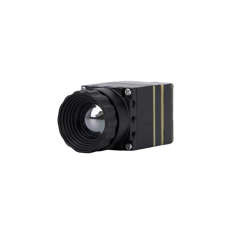
Seria MD 384×288 Niechłodzony Moduł Kamery Termowizyjnej na Podczerwień
Moduł kamery termowizyjnej Purpleriver serii MD został zaprojektowany z myślą o przemysłowej precyzji w wymagających zastosowaniach, w tym fizycznej ochronie obwodowej, automatycznym monitorowaniu temperatury maszyn, inspekcji elektrycznej i ładunkach systemów bezzałogowych. Napędzany wysokoczułą niechłodzoną matrycą mikrobolometryczną VOx o rastrze pikseli 12 μm pracującą w rozdzielczości 384×288, zapewnia ostry, wysokokontrastowy obraz termiczny w trudnych warunkach atmosferycznych.
Dzięki kompaktowej architekturze plug-and-play seria MD oferuje elastyczną łączność wielointerfejsową obsługującą jednoczesne lub wybieralne CVBS (analogowe), USB 2.0 i cyfrowe strumienie MIPI-CSI2. Wspierany przez wiedzę projektową sprzętu z HKUST oraz byłych liderów inżynierii Huawei HiSilicon, moduł obsługuje szeroką personalizację OEM/ODM, w tym niestandardowe uchwyty obiektywów optycznych, dopasowane krzywe algorytmów ISP i adaptację zastrzeżonych protokołów.

Mini 640 Niechłodzony Moduł Rdzenia Kamery Termowizyjnej LWIR do Dronów
Niechłodzony moduł obrazowania termowizyjnego Mini 640 zapewnia wykrywanie termiczne w wysokiej rozdzielczości w mikrokompaktowym formacie zaprojektowanym do gimbali dronów powietrznych, taktycznych platform FPV i przenośnej robotyki. Oferując rozdzielczość 640×512 (z wybieralnymi trybami 640×480) przy rastrze pikseli 12 μm, ten rdzeń zapewnia wyraźny obraz termiczny, wyjątkową ostrość krawędzi i minimalne zużycie energii.
Dzięki ultra-kompaktowym wymiarom obudowy wynoszącym zaledwie 21 mm × 21 mm, Mini 640 płynnie integruje się z ograniczonymi przestrzeniami gimbali. Oferuje wszechstronną elastyczność optyczną z szerokim wyborem ogniskowych: 5 mm, 9 mm, 13 mm, 18 mm, 35 mm, 50 mm, 75 mm, 100 mm i 150 mm atermalizowane soczewki germanowe. Obsługując bezpośrednio analogowe kompozytowe wideo CVBS wraz z łącznością USB UVC, został zaprojektowany do stabilnej pracy i solidnej adaptacji środowiskowej w ekstremalnych reżimach temperaturowych przemysłowych i lotniczych.
Aby uzyskać pełne karty katalogowe i informacje o międzynarodowej dystrybucji, zapoznaj się z naszą arabską analizą techniczną dotyczącą przemysłowych monokularów ręcznych, a także z naszym rosyjskim przewodnikiem inżynierskim na temat wyboru przemysłowej kamery termowizyjnej.
Podręcznik integracji elektrycznej i sprzętowej: zasilanie, impedancja i mostkowanie wielu magistral
Umieszczenie analogowego modułu termicznego na wbudowanej płycie nośnej PCB, w obudowie PTZ lub ładunku drona wymaga starannych decyzji projektowych. W warsztacie często spotykamy problemy z szumami spowodowane niedopasowaną impedancją, hałaśliwymi przetwornicami DC-DC lub złym uziemieniem.
Linia transmisyjna CVBS i dopasowanie impedancji
Kompozytowe sygnały wideo w paśmie podstawowym to niezbalansowane linie analogowe, które wymagają ścisłego zakończenia źródła i obciążenia wynoszącego $75\,\Omega$. Każde niedopasowanie impedancji wzdłuż ścieżek PCB lub okablowania powoduje odbicia sygnału. Na ekranie objawia się to jako duchy, dzwonienie, rozmycie krawędzi lub zniekształcenie fazy impulsu koloru.
- ⚙️ Prowadzenie ścieżek PCB: Poprowadź ścieżkę analogowego wideo CVBS jako falowód koplanarny z masą lub odniesienie mikropaskowe obliczone dla impedancji charakterystycznej $75\,\Omega \pm 5\%$. Trasę należy prowadzić możliwie najkrócej i nie prowadzić jej wzdłuż szybkich zegarów cyfrowych, linii SPI ani węzłów przełączających przetwornic DC-DC.
- ⚙️ Okablowanie połączeniowe: W ruchomych zespołach gimbala należy stosować miniaturowy, wysokogiętny kabel koncentryczny $75\,\Omega$, taki jak RG-179 z dielektrykiem PTFE i posrebrzanym oplotem miedzianym. W stałych instalacjach polowych o długości powyżej 100 metrów należy stosować podwójnie ekranowany kabel RG-59 lub RG-6 z pełnym uziemieniem ekranu 360 stopni przy tylnym korpusie złącza.
- ⚙️ Ochrona ESD i przeciwprzepięciowa: Porty analogowego wideo są narażone na kontakt z okablowaniem polowym. Bezpośrednio przy złączu należy umieścić diodę zabezpieczającą przed przepięciami (TVS) o bardzo małej pojemności. Pojemność złącza diody musi być mniejsza niż $C_D < 1,5\,\text{pF}$ aby zapobiec tłumieniu wysokich częstotliwości, przy wartościach ochrony do $\pm 15\,\text{kV}$ w powietrzu i $\pm 8\,\text{kV}$ przy kontakcie zgodnie z normą IEC 61000-4-2.
Projektowanie zasilania i tłumienie tętnień
Niechłodzone układy ROIC mikrobolometrów i przetworniki DAC wideo są wrażliwe na wahania szyn zasilających. Tętnienia napięcia na szynie wejściowej modulują napięcia polaryzacji czujnika, objawiając się jako poziome, przesuwające się pasy przydźwięku, szum rastrowy wysokiej częstotliwości lub stałe pionowe pasy.
- ⚙️ Sekwencjonowanie i regulacja zasilania: Rdzeń termiczny należy zasilać przez dedykowany, niskoszumny regulator liniowy LDO (Low-Dropout) oferujący wysoki współczynnik tłumienia tętnień zasilania (PSRR > 70 dB przy 100 kHz). Nigdy nie należy zasilać modułu analogowego bezpośrednio z regulatora impulsowego buck/boost bez stopnia filtru LC i koralika ferrytowego.
- ⚙️ Sieć odsprzęgająca: Bezpośrednio przy pinach VCC i GND modułu należy umieścić ceramiczne kondensatory odsprzęgające o niskim ESR (kondensator ceramiczny X7R $10\,\mu\text{F}$ sparowany z kondensatorami $0.1\,\mu\text{F}$ i $100\,\text{pF}$ C0G/NP0), aby wyeliminować zarówno tętnienia niskiej częstotliwości, jak i szumy RF wysokiej częstotliwości.
Architektura hybrydowa: jednoczesny analogowy wyświetlacz i cyfrowe przetwarzanie AI
Nowoczesne systemy polowe często wykorzystują hybrydową topologię podwójnej magistrali. W tej architekturze analogowe wyjście wideo CVBS przechodzi przez pierścień ślizgowy bezpośrednio do analogowego nadajnika 5,8 GHz lub wyświetlacza stacjonarnego, dając operatorowi natychmiastowy strumień wizyjny niezależnie od stanu komputera. Jednocześnie cyfrowy interfejs rdzenia (MIPI-CSI2 lub USB) przesyła surowe 14-bitowe klatki radiometryczne do wbudowanego procesora Edge AI (takiego jak NVIDIA Jetson, Rockchip RK3588 lub NXP i.MX8). Komputer brzegowy realizuje rozpoznawanie celów w czasie rzeczywistym (ATR), detekcję wtargnięcia na obwód lub alarmy progowe termiczne bez wprowadzania ani jednej milisekundy opóźnienia do głównego monitora lotu lub operatora.
Profile zastosowań przemysłowych i lotniczych o wysokiej niezawodności
Kluczowe zalety analogowych modułów termicznych — zerowe opóźnienie, odporność elektryczna, niskie wymagania okablowania i bezpośrednie wyjście wideo — czynią je idealnym wyborem w wielu wymagających środowiskach przemysłowych i operacyjnych w terenie.
Taktyczne ładunki gimbalowe UAV i rozpoznanie dronami FPV
Małe bezzałogowe systemy powietrzne (sUAS) i drony widokowe FPV (First-Person View) działają w ścisłych limitach rozmiaru, masy i mocy. W dynamicznych reżimach lotu opóźnienie kompresji cyfrowej pogarsza sterowanie lotem i omijanie przeszkód. Zamontowanie ultrakompaktowego rdzenia, takiego jak Mini 640 ($21\,\text{mm} \times 21\,\text{mm}$) wewnątrz 2-osiowego lub 3-osiowego mikrogimbala umożliwia bezpośrednią transmisję obrazu termicznego NTSC/PAL na żywo przez analogowy nadajnik 5,8 GHz (VTX) do gogli pilota. Pilot nawiguje przez mgłę, dym i korony drzew z zerowym opóźnieniem bufora.
Modernizacja istniejącej infrastruktury zabezpieczeń i nadzoru perymetrycznego
Duże obiekty przemysłowe — takie jak rafinerie ropy naftowej, morskie terminale cargo, podstacje elektroenergetyczne i zakłady chemiczne — często mają kilometry zainstalowanego kabla koncentrycznego $75\,\Omega$ RG-59. Wymiana starszych analogowych kamer CCTV światła widzialnego na moduły termowizyjne MD Series 384×288 CVBS umożliwia pełny monitoring termiczny w nocy i przy złej pogodzie z wykorzystaniem istniejącej magistrali koncentrycznej. Pozwala to zaoszczędzić tysiące dolarów na kosztach ponownego okablowania i uniknąć przestojów systemu związanych z przeciąganiem nowego kabla Ethernet Cat6 lub instalowaniem przełączników sieciowych PoE w strefach zagrożonych wybuchem lub niebezpiecznych obszarach procesowych.
Monitorowanie podstacji wysokiego napięcia i automatyzacja procesów przemysłowych
Place transformatorowe wysokiego napięcia i odlewnie metali generują silne pola elektromagnetyczne oraz skoki napięcia przejściowego podczas cykli przełączeniowych. W tych obszarach cyfrowe warstwy PHY Ethernetu mogą doświadczać gubienia pakietów, przepełnienia buforów i zrywania negocjacji sieciowych. Analogowe rdzenie kamer termowizyjnych pracujące na podwójnie ekranowanych liniach koncentrycznych zapewniają doskonałą odporność elektromagnetyczną. Zapewniają one bezkontaktowy monitoring termiczny szyn zbiorczych, odłączników i wykładzin ogniotrwałych, alarmując sterowniki PLC zakładu o niebezpiecznych gorących punktach, zanim dojdzie do wyładowania łukowego lub pożaru.
Film demonstracyjny miniaturowego rdzenia termowizyjnego 640×512
Często zadawane pytania (FAQ)
Jaka jest główna zaleta stosowania analogowego modułu kamery termowizyjnej (CVBS) w porównaniu z formatami cyfrowymi?
Czy moduły kamer termowizyjnych Purpleriver mogą obsługiwać jednocześnie wyjścia analogowe i cyfrowe?
Jak temperatura otoczenia wpływa na niechłodzony moduł termowizyjny i w jaki sposób rdzeń to kompensuje?
Jaka jest różnica między wyjściami CVBS NTSC a PAL w modułach kamer termowizyjnych?
📚 Referencje i dalsza lektura
- Standard branżowy: Dowiedz się więcej o fizyce rdzenia na Wikipedia Obrazowanie termowizyjne portalu referencyjnym.
- Pozyskiwanie i komponenty: Pozyskiwanie zweryfikowanych podsystemów optoelektronicznych przez Komponenty przemysłowe KUYANG.
- Analiza zastosowań: Obejrzyj nasze techniczne wdrożenie w przewodniku wideo po modułach kamer termowizyjnych z dronami.
- Wybór międzynarodowy (arabski): Przeczytaj nasz regionalny przewodnik po wyborze przemysłowego monokularu ręcznego w języku arabskim.
- Przewodnik techniczny (rosyjski): Zapoznaj się z naszą recenzją na temat wyboru przemysłowej kamery termowizyjnej w języku rosyjskim.