Moduł kamery termowizyjnej o wysokiej rozdzielczości dla Raspberry Pi: Kompletny przewodnik integracji Edge AI
24 czerwca 2026
Kompletny przewodnik po integracji modułu kamery termowizyjnej: Rozwiązania 384x288 dla dronów, Raspberry Pi i projektów OEM B2B
1 lipca 2026
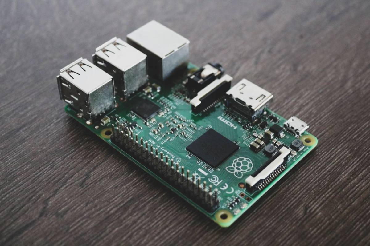
Moduł kamery termowizyjnej USB o wysokiej rozdzielczości dla Raspberry Pi: Przewodnik integracji 640x512
Oto sedno: jeśli próbujesz wdrożyć termowizję wysokiej rozdzielczości na komputerach jednopłytkowych (SBC), takich jak Raspberry Pi, prawdopodobnie natknąłeś się na jakąś przeszkodę. Wczesne eksperymenty z matrycami termopil I2C o niskiej rozdzielczości sprawdzały się w projektach hobbystycznych, ale nowoczesne zastosowania przemysłowe wymagają poważnego sprzętu. Mówimy o wysokiej czułości termicznej (NETD ≤ 50 mK), szybkich klatkach na sekundę i gęstej rozdzielczości przestrzennej. Ten przewodnik to kompletny, praktyczny podręcznik integracji systemu dla inżynierów sprzętu, specjalistów ds. badań i rozwoju oraz architektów oprogramowania, którzy składają moduł kamery termowizyjnej usb dla raspberry pi. W naszym sklepie wiemy, że sukces zależy od zrozumienia fizyki, wyboru odpowiedniego interfejsu, dopasowania optyki i pisania wydajnych potoków oprogramowania. Omówimy fizykę niechłodzonych czujników długofalowej podczerwieni (LWIR), porównamy szczegóły techniczne interfejsów USB/UVC i MIPI CSI-2, przeanalizujemy wybór obiektywów i przejdziemy przez gotowy do użycia potok Pythona wykorzystujący sterowniki Linux V4L2 i OpenCV.
Spis treści
- 👉 Fizyka niechłodzonych czujników mikrobolometrycznych LWIR
- 👉 Integracja USB vs. MIPI dla Raspberry Pi
- 👉 Kryteria wyboru optyki i obiektywów
- 👉 Specyfikacje techniczne i wybór produktu
- 👉 Integracja oprogramowania: V4L2, OpenCV i Python SDK
- 👉 Zaawansowane przetwarzanie obrazu: mapowanie radiometryczne i NUC
- 👉 Wdrożenia przemysłowe w terenie
- 👉 FAQ – szczegółowe zagadnienia techniczne
Fizyka niechłodzonych czujników mikrobolometrycznych LWIR
Aby zbudować system termowizyjny, który faktycznie działa w terenie, trzeba dokładnie przyjrzeć się leżącej u jego podstaw fizyce. Standardowe przetworniki CMOS i CCD rejestrują odbite światło widzialne w zakresie od 400 nm do 700 nm. Termowizja jest inna. Obserwujemy pasmo długofalowej podczerwieni (LWIR), które rozciąga się od 8 µm do 14 µm.
Wszystko wokół nas – silniki, maszyny, płytki drukowane, ludzkie ciała – emituje energię cieplną jako promieniowanie ciała doskonale czarnego. Prawo Plancka i prawo przesunięć Wiena opisują to zachowanie. Kiedy obliczamy szczytową długość fali emisji, prawo Wiena upraszcza to:
λmax = 2897,8 µm·K / T
Jeśli twój cel ma normalną temperaturę pokojową 300 K (około 27°C lub 80°F), jego szczytowa emisja wypada dokładnie przy 9,66 µm. Leży to idealnie w centrum atmosferycznego okna transmisyjnego LWIR. To pasmo jest kluczowe, ponieważ gazy atmosferyczne, takie jak dwutlenek węgla i para wodna, nie pochłaniają tu dużo energii, co pozwala sygnałowi dotrzeć do czujnika z minimalnym tłumieniem.
Teoretyczne wskaźniki wydajności:
Tlenek wanadu (VOx) vs. amorficzny krzem (a-Si): W praktyce matryce rdzeni VOx są preferowane w zastosowaniach wysokiej klasy. Materiał VOx wykazuje lepszy temperaturowy współczynnik rezystancji (TCR) w porównaniu z krzemem. Minimalizuje to szum termiczny i daje czystszy surowy obraz. Wybór modułu kamery termowizyjnej wysokiej rozdzielczości 640x512 z niechłodzonym rdzeniem LWIR wykorzystującego podłoża VOx zapewnia, że surowe szczegóły celu pozostają ostre w szerokim zakresie warunków pracy.
Większość wytrzymałych komercyjnych modułów kamer wykorzystuje niechłodzone mikrobolometry. Wyobraź sobie matrycę maleńkich, zawieszonych mostków krzemowych, z których każdy pokryty jest materiałem czułym na temperaturę, takim jak tlenek wanadu. Gdy fotony LWIR trafiają w piksel, mostek nagrzewa się, zmieniając swoją oporność elektryczną.
Układ odczytu (ROIC) przepuszcza spolaryzowany prąd przez matrycę, mierzy te zmiany oporności i tworzy cyfrowy obraz termiczny. Dwie kluczowe zmienne decydują o tym, jak dobrze działa sensor:
- ⚙️ Rozstaw pikseli: Odległość między środkami sąsiednich pikseli. Zmniejszenie jej z 17 µm do 12 µm pozwala upakować matrycę 640x512 w kompaktowy, lekki rdzeń, który mieści się na małych dronach lub w ciasnych obudowach.
- ⚙️ NETD (Równoważna szumowo różnica temperatur): To jest twój wskaźnik sygnału do szumu. Określa najmniejszą różnicę temperatur, jaką kamera może rozróżnić. Jeśli wykonujesz diagnostykę wymagającą szczegółowości, potrzebujesz NETD ≤40 mK lub ≤50 mK. Wyższe wartości sprawiają, że obraz wygląda jak stare zakłócenia telewizyjne.
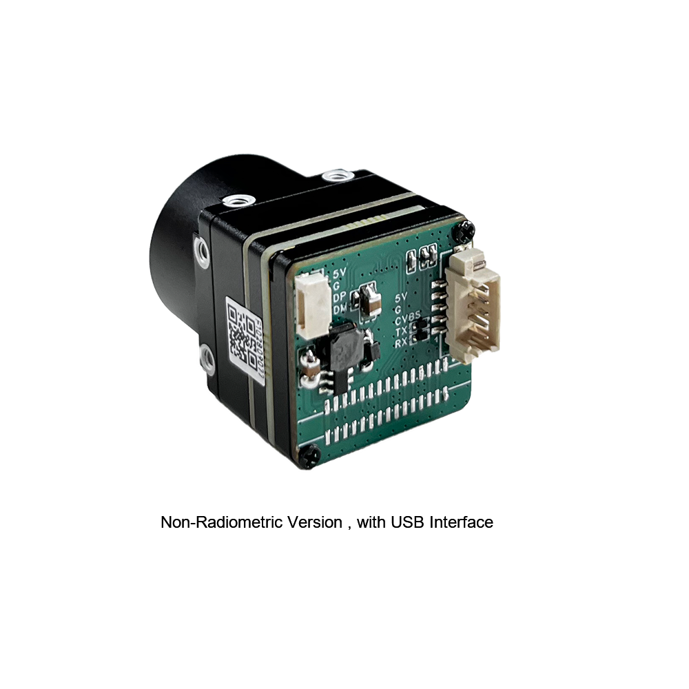
Integracja USB vs. MIPI dla Raspberry Pi
Podczas integracji wysokiej klasy rdzenia termicznego z Raspberry Pi stajesz przed kluczowym wyborem: interfejs USB (protokół UVC) czy natywny MIPI CSI-2?
Interfejs USB (protokół UVC)
Moduły USB opierają się na standardowym mikrokodzie USB Video Class (UVC) działającym na wbudowanym mikrokontrolerze lub FPGA. Układ pakuje surową klatkę z ROIC do formatu cyfrowego (YUYV lub surowa 16-bitowa skala szarości) i przesyła ją przez magistralę USB.
Dużą zaletą jest tutaj łatwość użycia. Linux od lat ma natywne uvcvideo sterowniki wbudowane w jądro. Podłącz moduł, a natychmiast pojawi się jako /dev/video0. Żadnych niestandardowych nakładek device-tree, błędów kompilacji ani problemów z dopasowaniem jądra. Możesz przenieść tę samą kamerę USB z Raspberry Pi 4 na Pi 5 lub standardowy przemysłowy komputer x86 z Linuxem bez zmiany ani jednej linii kodu. Jaki jest kompromis? USB wprowadza nieco większe opóźnienia (zwykle dodatkowe 10 ms do 30 ms) i zużywa odrobinę więcej cykli CPU ze względu na wymagania parsowania sterownika kontrolera hosta.
Interfejs MIPI CSI-2
MIPI CSI-2 to opcja o wysokiej wydajności. Ten interfejs omija pośrednie mikrokontrolery, przesyłając surowe bufory klatek szeregowych bezpośrednio do Video Core ISP układu SoC Raspberry Pi lub do pamięci RAM przez DMA.
Jeśli projektujesz automatyczne systemy śledzenia lub lekkie urządzenia zasilane bateryjnie (takie jak gimbale dronów), gdzie liczy się każda milisekunda i miliwat, MIPI jest standardowym wyborem. Oferuje niskie opóźnienia i minimalne obciążenie CPU.
Wadą jest sztywność sprzętowa. Musisz kompilować nakładki device-tree (.dtbo) specyficzne dla dokładnej wersji twojego jądra. Jeśli zaktualizujesz system operacyjny, potok kamery może przestać działać, dopóki sterownik nie zostanie załatany. Połączenia fizyczne są również delikatne; masz do czynienia z kruchymi taśmami elastycznymi lub niestandardowymi wiązkami mikro-koncentrycznymi. Jeśli prowadzisz je przez ciasne złącze obrotowe, wymagane są specjalistyczne zespoły wiązek wysokiej prędkości od ekspertów takich jak Przewód mikrowspółosiowy męski , aby utrzymać sygnały ekranowane i czyste.
Kryteria wyboru optyki i obiektywów
W przeciwieństwie do standardowych kamer, które używają tanich szklanych lub plastikowych soczewek, konstrukcje LWIR wymagają specjalistycznych materiałów przepuszczających podczerwień. Standardowe szkło borokrzemowe jest całkowicie nieprzezroczyste dla promieniowania LWIR. Zamiast tego używamy elementów z germanu (Ge), krzemu (Si) lub formowanego szkła chalkogenidkowego.
| Materiał | Współczynnik załamania (n @10µm) | Kluczowe cechy inżynieryjne |
|---|---|---|
| German (Ge) | ~4.0 | Doskonałe właściwości transmisyjne w paśmie 8-14µm; drogi; doświadcza termicznego dryfu ostrości w granicznych warunkach pracy. |
| Szkło chalkogenidkowe (stopy As-Se-Ge) | ~2,5 do 2,8 | Wysoce formowalna optyka umożliwiająca złożone geometrie; minimalny termiczny dryft ogniskowej; wysoce opłacalny współczynnik załamania światła. |
Podczas dobierania obiektywu do sensora należy obliczyć rozdzielczość przestrzenną. Reprezentuje ją chwilowe pole widzenia (iFOV), które określa fizyczny obszar pola rozdzielany przez pojedynczy piksel przy danej odległości roboczej:
iFOV = Rozmiar piksela (µm) / Ogniskowa (mm)
Obliczmy to na przykładzie modułu o rozdzielczości 640x512 z pikselem 12 µm i standardowym obiektywem 9 mm:
iFOV = 12 μm / 9 mm ≈ 1,33 mrad
Oznacza to, że z odległości 1 metra każdy pojedynczy piksel rozdziela fizyczny kwadrat o boku 1,33 mm. Z odległości 100 metrów ten obszar rozszerza się do 133 mm (około 5,2 cala). Jeśli szukasz lokalnych anomalii na słupach energetycznych lub turbinach wiatrowych, cel musi pokrywać co najmniej 3x3 piksele, aby zapewnić wiarygodny pomiar. Dlatego wybór ogniskowej ma kluczowe znaczenie przed wdrożeniem sprzętu.
Do wymagających zastosowań, precyzyjnie formowane soczewki chalkogenkowe od liderów technologii, takich jak LightPath Technologies zapewniają wysoką transmisję światła przy zachowaniu ostrości w szerokim zakresie wahań temperatury. Minimalizuje to potrzebę ciągłych programowych korekt ostrości podczas pracy na zewnątrz.
Specyfikacje techniczne i wybór produktu
Dla konstrukcji sprzętowych opartych na architekturze Raspberry Pi oferujemy dwa przemysłowe, niechłodzone moduły sensorów mikrobolometrycznych. Jeden jest przeznaczony do wdrożenia USB typu plug-and-play, a drugi to natywny moduł MIPI zbudowany do bezpośredniego interfejsu o niskich opóźnieniach.
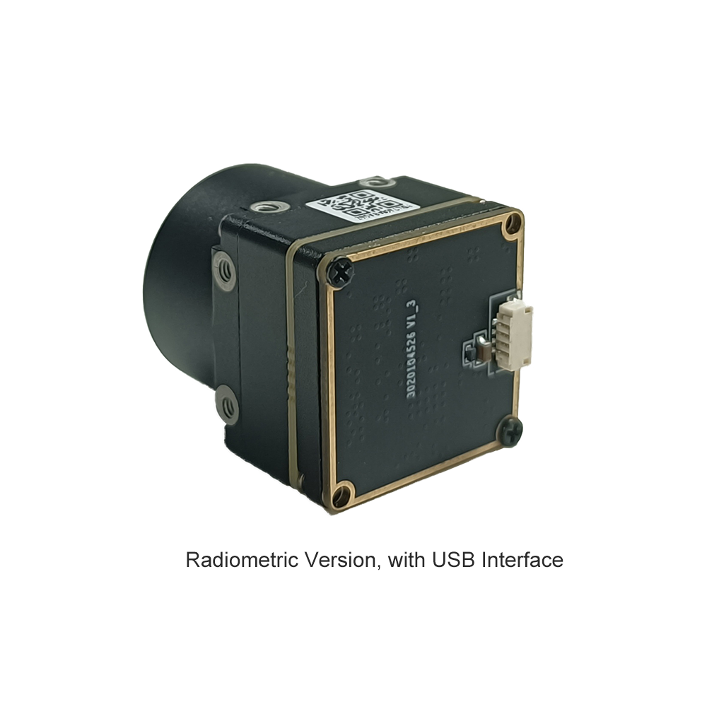
Produkt 1: Niechłodzony miniaturowy moduł kamery termowizyjnej LWIR USB 640*512 do dronów, podobny do DJI

Ten miniaturowy, niechłodzony moduł termowizyjny na podczerwień zapewnia ostry, szczegółowy obraz w ultra-kompaktowej obudowie. Idealnie nadaje się do ładunków dronów i zdalnych systemów monitoringu przemysłowego.
Kluczowe specyfikacje techniczne:
| Format / Rozmiar | Ultra-miniaturowa obudowa 21 mm * 21 mm |
| Opcje obiektywów (ogniskowa) | Opcje ogniskowych: 5 mm / 9 mm / 13 mm / 18 mm / 35 mm / 50 mm / 75 mm / 100 mm / 150 mm |
| Opcje rozdzielczości | Matryca o wysokiej gęstości 640x512 (z kompatybilnością przycięcia do 640x480) |
| Kompatybilność integracyjna | Solidne uszczelnienie konstrukcyjne, stabilność termiczna, zgodność ze standardem UVC przez USB |
Produkt 2: Niechłodzony moduł kamery termowizyjnej MIPI 640 384 256 9 mm do dronów

Moduł termowizyjny MIPI serii Mini2 przesyła surowe dane termiczne z minimalnym opóźnieniem. Jest zoptymalizowany do bezpośrednich pętli przetwarzania i lekkich systemów lotniczych.
Kluczowe specyfikacje techniczne:
| Rozdzielczość podstawowa | Aktywna matryca pikseli 640x512 (z opcjami strukturalnymi 384 i 256) |
| Optyka domyślna | Konfiguracja z wysokiej jakości soczewką germanową o ogniskowej 9 mm |
| Interfejs sprzętowy | Bezpośrednia sygnalizacja MIPI CSI-2 (zoptymalizowana pod kątem minimalnych opóźnień i bezpośredniego przetwarzania sprzętowego) |
| Profil obrazowania | Ostry i wyraźny obraz termiczny, lekka konstrukcja dla dronów i platform lotniczych |
Integracja oprogramowania: V4L2, OpenCV i Python SDK
Przejdźmy do praktycznego kodowania. Aby pobierać surowe, nieskompresowane klatki z kamery termowizyjnej UVC na Raspberry Pi, używamy standardowego sterownika Linux Video4Linux2 (V4L2).
Krok 1: Sprawdź właściwości systemu
Przed napisaniem kodu sprawdź, czy system operacyjny widzi kamerę. Podłącz kamerę i uruchom:
# Zainstaluj zestaw narzędzi v4l2
Szukaj formatów klatek, takich jak YDUV, YUYV, lub bezpośredniej 16-bitowej skali szarości (oznaczonej jako Y16 lub SZARY). Jeśli twój potok przetwarzania potrzebuje bezpośrednich pomiarów radiometrycznych, pożądany jest surowy format 16-bitowy.
Krok 2: Wielowątkowe przechwytywanie w Pythonie w warunkach rzeczywistych
Jeśli wywołasz VideoCapture.read() w jednowątkowej pętli Pythona, liczba klatek na sekundę spadnie. W naszym warsztacie uruchamiamy przechwytywanie z czujnika w dedykowanym wątku w tle, aby zapobiec blokowaniu. Dzięki temu potok kamery działa stabilnie, podczas gdy na głównym wątku wykonujesz wymagające zadania wizji komputerowej.
"""
RPi LWIR Thermal Acquisition and Multi-Threaded Frame Buffer Pipe
Optimized for 640x512 Uncooled USB Camera Cores.
"""

import cv2
import numpy as np
import time
import threading

class USBThermalCamera:
    def __init__(self, device_index=0, width=640, height=512):
        self.device_index = device_index
        self.width = width
        self.height = height
        self.cap = None
        self.frame = None
        self.running = False
        self.lock = threading.Lock()

    def initialize_capture(self):
        # Open video device via standard V4L2 utility backend
        self.cap = cv2.VideoCapture(self.device_index, cv2.CAP_V4L2)
        if not self.cap.isOpened():
            raise RuntimeError(f"Failed to access V4L2 sensor node: /dev/video{self.device_index}")

        # Bind payload stream resolutions to the requested parameters
        self.cap.set(cv2.CAP_PROP_FRAME_WIDTH, self.width)
        self.cap.set(cv2.CAP_PROP_FRAME_HEIGHT, self.height)

        # Verify active driver configuration values
        active_w = int(self.cap.get(cv2.CAP_PROP_FRAME_WIDTH))
        active_h = int(self.cap.get(cv2.CAP_PROP_FRAME_HEIGHT))
        print(f"[INFO] Camera pipeline running at target configuration: {active_w}x{active_h} px")

    def start_grab_thread(self):
        self.running = True
        self.thread = threading.Thread(target=self._update_loop, daemon=True)
        self.thread.start()

    def _update_loop(self):
        while self.running:
            ret, raw_frame = self.cap.read()
            if not ret or raw_frame is None:
                time.sleep(0.005)
                continue

            with self.lock:
                self.frame = raw_frame.copy()

    def grab_latest_frame(self):
        with self.lock:
            if self.frame is None:
                return None
            return self.frame.copy()

    def terminate_pipeline(self):
        self.running = False
        if hasattr(self, 'thread'):
            self.thread.join(timeout=1.0)
        if self.cap:
            self.cap.release()
        print("[INFO] Thermal core pipeline shutdown gracefully.")

if __name__ == "__main__":
    cam = USBThermalCamera(device_index=0, width=640, height=512)
    try:
        cam.initialize_capture()
        cam.start_grab_thread()
        print("[PROCESS] Streaming initialized. Press 'Q' to safely exit.")

        while True:
            frame = cam.grab_latest_frame()
            if frame is None:
                time.sleep(0.01)
                continue

            # Convert incoming YUYV channel arrays to basic greyscale structures
            gray_frame = cv2.cvtColor(frame, cv2.COLOR_BGR2GRAY)

            # Apply dynamic colormaps to visually enhance thermal variance
            # COLORMAP_INFERNO outputs excellent human eye thermography separation
            thermal_color = cv2.applyColorMap(gray_frame, cv2.COLORMAP_INFERNO)

            # Identify absolute thermal peaks within the target frame space
            min_val, max_val, min_loc, max_loc = cv2.minMaxLoc(gray_frame)

            # Draw tracking overlay representing the peak thermal zone
            cv2.circle(thermal_color, max_loc, 8, (0, 0, 255), 2)
            cv2.putText(thermal_color, f"PEAK: {max_val}", (15, 30),
                        cv2.FONT_HERSHEY_SIMPLEX, 0.6, (0, 255, 0), 2)

            cv2.imshow("LWIR 640x512 Realtime Core Pipeline", thermal_color)
            if cv2.waitKey(1) & 0xFF == ord('q'):
                break

    except Exception as err:
        print(f"[FATAL EXCEPTION]: {err}")
    finally:
        cam.terminate_pipeline()
        cv2.destroyAllWindows()
Zaawansowane przetwarzanie obrazu: mapowanie radiometryczne i NUC
Surowe dane wideo to dopiero początek. Skonfigurowanie profesjonalnego systemu monitorowania termicznego wymaga dwóch zaawansowanych etapów przetwarzania: korekcji niejednorodności (NUC) i Mapowanie radiometryczne.
korekcji niejednorodności (NUC)
Ponieważ piksele mikrobolometru są maleńkie i zawieszone, ich surowe właściwości elektryczne zmieniają się w czasie, gdy korpus kamery się nagrzewa. To dryftowanie skutkuje zaszumionym, ziarnistym obrazem — efektem zwanym "szumem wzorca przestrzennego"."
Aby temu zaradzić, wysokowydajne rdzenie kamer na ułamek sekundy opuszczają małą wewnętrzną przesłonę mechaniczną przed czujnikiem optycznym. Prezentuje to matrycy idealnie jednolity cel termiczny. Wewnętrzny procesor mierzy surowe wartości pikseli względem średniej, generując mapę korekcji offsetu. Chociaż nasze moduły mogą przeprowadzać tę kalibrację automatycznie, programiści pracujący z precyzyjnymi systemami radiometrycznymi często wyzwalają tę korekcję ręcznie za pomocą poleceń szeregowych, aby uniknąć przerw podczas krytycznych nagrań.
Kalibracja temperatury radiometrycznej
Do przemysłowego pomiaru temperatury potrzebujesz konfiguracji radiometrycznej. Zamiast renderować standardowe 8-bitowe wartości wizualne, moduł eksportuje surową 16-bitową liczbę całkowitą reprezentującą rzeczywistą intensywność ADC każdego piksela. Wysokowydajne moduły zazwyczaj używają standardowej skali liniowej:
Tcel = (Wartość piksela × Współczynnik skalowania) - Przesunięcie
Jeśli Twój moduł używa standardowego współczynnika skalowania 0,01 K, przekształcanie surowych odczytów pikseli na stopnie Celsjusza lub Kelwina jest proste:
T (Kelwin) = Wartość_ADC_Piksela × 0,01
T (Celsjusz) = (Wartość_ADC_Piksela × 0,01) - 273,15
W zastosowaniach rzeczywistych należy również uwzględnić poprawkę na **Emisyjność celu (ε)**. Wartość ta opisuje, jak efektywnie obiekt wypromieniowuje ciepło w porównaniu z teoretycznym ciałem doskonale czarnym (gdzie ε = 1,0). Jeśli mierzysz polerowane metale, takie jak miedź elektrolityczna lub aluminiowe tuleje, ich emisyjność może spaść do 0,15 lub mniej. Oznacza to, że surowy czujnik będzie rejestrował odbicia ciepła otoczenia, a nie rzeczywistą temperaturę metalu. Aby uzyskać dokładne odczyty, należy dostosować obliczenia w post-processingu, aby skorygować te odbicia:
def oblicz_temperature_absolutna(wartosc_piksela, emisyjnosc=0.95, t_otoczenia_k=298.15):
Wdrożenia przemysłowe w terenie
Oto jak inżynierowie wykorzystują te zintegrowane płytki mikrobolometryczne 640x512 we wdrożeniach terenowych:
A. Inspekcja lotnicza z UAV i mapowanie dronami
Montując te lekkie rdzenie termowizyjne na małych dronach, operatorzy sieci użyteczności publicznej mogą przeprowadzać zautomatyzowane inspekcje farm słonecznych, łopat turbin wiatrowych i linii przesyłowych wysokiego napięcia.
Korzystając z kompaktowych zestawów, takich jak Raspberry Pi Compute Module 4 (CM4), zespoły lotnicze mogą uruchamiać stabilizację obrazu w czasie rzeczywistym i georeferencjonowanie celów bez dodawania nadmiernej masy do płatowca, zachowując czas lotu.
B. Automatyka przemysłowa i ciągłe monitorowanie termiczne
W zakładach produkcyjnych awarie maszyn mogą powodować kosztowne przestoje. Inżynierowie wdrażają płytki Raspberry Pi w szczelnych, przemysłowych obudowach, aby stale monitorować łożyska przenośników, transformatory i zasoby fizyczne, takie jak kotły.
Te zestawy obserwują skoki temperatury w oparciu o standardowe do czego służy kamera termowizyjna wytyczne profilowania. Jeśli komponent przekroczy bezpieczne limity, Raspberry Pi może wyzwalać alerty bezpośrednio przez przemysłowe sieci polowe, używając protokołów takich jak Modbus TCP lub MQTT.
C. Ochrona obwodowa i inteligencja brzegowa
Podczas gdy standardowe kamery mają trudności w całkowitej ciemności, mgle lub gęstej roślinności, czujniki LWIR sprawdzają się doskonale. Połączenie wysokorozdzielczego rdzenia termowizyjnego 640x512 z lekkimi modelami Edge AI (takimi jak TFLite YOLOv8) na Raspberry Pi 5 umożliwia wysoce niezawodne wykrywanie intruzów. Taka konfiguracja może dostrzec sylwetki ludzi z odległości setek metrów, ignorując jednocześnie szum tła, taki jak kołyszące się gałęzie i wiatr.
Jeśli szukasz podstawowych konfiguracji sprzętowych i narzędzi diagnostycznych, sprawdź nasz ogólny przewodnik integracji termicznej. Obejmuje on obudowy strukturalne i ochronne okienka kryształowe do trudnych, zapylonych środowisk.
FAQ – szczegółowe zagadnienia techniczne
Dlaczego powinienem zmodernizować czujnik I2C, taki jak MLX90640, do modułu kamery termowizyjnej USB dla Raspberry Pi?
Potem jest kwestia prędkości. I2C to wolny, szeregowy interfejs. Nawet po podkręceniu, uzyskujesz ospałe 4 do 8 Hz. Kamera USB przesyła strumień przy płynnych 25 Hz przez natywną magistralę o wysokiej przepustowości, korzystając ze standardowych protokołów UVC.
Wreszcie, jest jakość rozdzielczości. Tanie matryce termopilowe cierpią z powodu wysokiego poziomu szumów czujnika, co oznacza, że ich NETD często wynosi około 100 mK do 150 mK. Profesjonalny rdzeń mikrobolometryczny VOx zapewnia NETD ≤ 50 mK. Oznacza to, że można rozróżnić subtelne różnice temperatur do 0,05°C, co jest niezbędne do szczegółów takich jak śledzenie przepływu ciepła na obwodach drukowanych czy lokalizowanie wycieków płynów za płytą gipsowo-kartonową.
Jak przesyłać strumieniowo obraz termowizyjny w czasie rzeczywistym na Raspberry Pi OS za pomocą waszego modułu?
uvcvideo sterownikiem jądra dołączonym do wydań Raspberry Pi OS, takich jak Debian Bookworm lub Bullseye. Nie są wymagane żadne niestandardowe sterowniki ani łatki jądra.
Po podłączeniu można przechwytywać klatki bezpośrednio w Pythonie za pomocą standardowych wywołań OpenCV. Aby uniknąć opóźnień, zalecamy pobieranie klatek w wątku w tle i przekazywanie ich do głównej aplikacji, gdzie można zastosować mapy fałszywych kolorów, takie jak INFERNO lub JET, w celu wyraźnej wizualizacji.
Jaki jest aktywny pobór mocy i wymagania dotyczące odprowadzania ciepła przy pracy ciągłej?
Jeśli kamera jest umieszczona w szczelnej obudowie lub gondoli drona, zalecamy montaż bezpośrednio do aluminiowej grodzi lub podwozia za pomocą taśmy termoprzewodzącej lub mosiężnych kołków dystansowych. Utrzymywanie korpusu modułu w niskiej temperaturze minimalizuje częstotliwość cykli wewnętrznej migawki NUC, zapewniając bardziej stabilny, nieprzerwany strumień wideo.
Czy mogę wykonywać bezwzględny pomiar temperatury (radiometrię) za pomocą tych niechłodzonych modułów kamer LWIR?
Stosując w kodzie przesunięcia kalibracyjne naszego rdzenia, program może konwertować te surowe wartości ADC na rzeczywiste odczyty w Kelwinach lub stopniach Celsjusza w czasie rzeczywistym. Po skompensowaniu emisyjności powierzchni, system zapewnia dokładność bezwzględną w granicach ±2°C.
📚 Piśmiennictwo i dalsze lektury
- ✅ Standard branżowy: LightPath Technologies
- ✅ Systemowe magistrale fizyczne: Przewód mikrowspółosiowy męski
- ✅ Powiązany przewodnik: Integracja wysokorozdzielczego rdzenia termowizyjnego 640x512