Высокопроизводительная интеграция тепловизионного модуля: Edge AI и OEM-решения для БПЛА
12 августа 2026 года
Руководство по выбору высокопроизводительного тепловизионного модуля для OEM и дронов
Когда вы проектируете системы для автономной робототехники, воздушного наблюдения или промышленного профилактического обслуживания, интеграция модуля корпоративного уровня тепловизионный модуль — это не просто приятная функция, чтобы похвастаться, а важнейший архитектурный выбор. Современные оптико-электронные системы должны выдавать четкие тепловые данные в суровых атмосферных условиях, густом дыму, тумане и при нулевой освещенности. Но вот реальность: втиснуть неохлаждаемое длинноволновое инфракрасное (LWIR) ядро в ограниченные по пространству подвесы БПЛА, портативное инспекционное оборудование или автоматизированные охранные полезные нагрузки означает балансировку оптических характеристик, тепловой чувствительности, задержки обработки и физических размеров. Как инженеры оптических систем, мы постоянно идем на трудные компромиссы — например, балансируем шаг пикселя относительно апертуры объектива или выбираем легкие платы обработки на ASIC вместо полнофункциональных радиометрических SDK-платформ, чтобы проект оставался в рамках цели.
Получение реальной эффективности тепловидения сводится к оптимизации МОГП-С (Размер, Вес, Мощность и Стоимость) без ухудшения характеристик детектора. Создаете ли вы оборонные дроны с автономным распознаванием целей или настраиваете промышленные IoT-тепловые датчики для круглосуточного мониторинга подстанций, выбор правильного ядра требует твердого понимания физики микроболометров, стандартов интерфейсов (RTSP поверх IP против аналогового CVBS со сверхнизкой задержкой) и алгоритмов коррекции неоднородности (NUC). Это руководство по выбору разбирает основные принципы, инженерные рабочие процессы и реальные спецификации, необходимые для интеграции OEM-движков тепловизионных камер в пользовательские аппаратные установки.
Содержание
- 👉 Основы фазоинженерного тепловизионного модуля
- 👉 Стратегия оптимизации SWaP-C для БПЛА и автономных полезных нагрузок
- 👉 Инженерия динамического видеоинтерфейса: RJ45 RTSP против аналогового CVBS
- 👉 Комплексное OEM-сравнение продуктов и спецификационный движок
- 👉 Оптическая калибровка, NUC и метрики измерения температуры
- 👉 Промышленный технический FAQ-справочник
Основы фазоинженерного тепловизионного модуля
Интегрированная тепловизионная камера тепловизионный модуль использующий длинноволновую инфракрасную (LWIR) технологию, работает, улавливая тепловое излучение, испускаемое поверхностными объектами в спектральном диапазоне от 8 мкм до 14 мкм. В отличие от стандартных оптических датчиков, которым нужен окружающий свет, неохлаждаемая тепловая микроболометрическая матрица обнаруживает разницу в излучении черного тела и превращает сырую кинетическую теплоту в четкие цифровые тепловые карты. Эта независимость от видимого света делает инфракрасный камерный движок незаменимым для операций в темноте, поисково-спасательных (SAR) миссий, проверок электрических шкафов и систем раннего обнаружения пожара.
Чтобы понять, как тепло превращается в пригодный для использования видеопоток или радиометрическую температурную сетку, давайте пошагово пройдемся по аппаратному конвейеру:
- ⚙️ Германиевая / халькогенидная оптика: Стандартное оптическое стекло полностью блокирует инфракрасный свет. Поэтому инфракрасное ядро полагается на просветленные (AR) германиевые или халькогенидные линзы, спроектированные для пропускания фотонов 8–14 мкм при подавлении оптических искажений.
- ⚙️ Неохлаждаемая микроболометрическая детекторная матрица: Инфракрасное излучение проходит через линзу и попадает на крошечную подвешенную микроболометрическую матрицу из термочувствительных материалов. Когда фотоны нагревают подвешенные мостики, их электрическое сопротивление изменяется прямо пропорционально температурному коэффициенту сопротивления (TCR) материала.
- ⚙️ Интегральная схема считывания (ROIC): Прямо под матрицей микроболометров находится КМОП-матрица ROIC. ROIC считывает изменения сопротивления попиксельно, преобразуя микроскопические электрические колебания в чистые цифровые отсчеты.
- ⚙️ Бортовой процессорный модуль (ASIC/FPGA): Цифровые отсчеты поступают в специализированный бортовой процессор. Здесь в реальном времени выполняются алгоритмы коррекции неоднородности (NUC), замены дефектных пикселей (BPR), шумоподавления и обработки динамического диапазона, формируя чистое высококонтрастное видео или калиброванные температурные профили.
- ⚙️ Мультипротокольный интерфейсный бэкенд: Наконец, бэкенд упаковывает видео или радиометрическую телеметрию в стандартизированные выходные сигналы — например, аналоговые потоки CVBS с нулевой задержкой или IP-потоки RTSP/ONVIF через Ethernet RJ45.
Физика детекторного ядра: VOx против a-Si
В основе любого современного OEM-тепловизионного модуля лежат тонкопленочные резисторы из оксида ванадия (VOx) или аморфного кремния (a-Si), установленные на микромеханической кремниевой ROIC. Выбор между этими материалами — одно из важнейших решений при подборе оборудования:
- ✅ Оксид ванадия (VOx): Микроболометры VOx обладают значительно более высоким температурным коэффициентом сопротивления (TCR). Проще говоря: более высокая электрическая чувствительность, меньший уровень шума и надежная долговременная стабильность. VOx является золотым стандартом для высокоточных промышленных инспекций, оборонных полезных нагрузок и корпоративного дрон-оборудования, где важна регистрация перепадов температуры менее градуса.
- ✅ Аморфный кремний (a-Si): Аморфный кремний обеспечивает равномерный пространственный отклик по всей фокальной плоскости и снижает производственные затраты при крупносерийном выпуске. Хотя ядра на a-Si, как правило, немного менее чувствительны, чем VOx, их более низкая цена делает их идеальными для коммерческих систем безопасности и бюджетных потребительских инструментов.
Пространственное разрешение и динамика шага пикселя
Разрешение матрицы определяет пространственную детализацию, поле зрения (iFOV) и пространственные диапазоны обнаружения, распознавания и идентификации (DRI) на основе стандартных критериев Джонсона:
| Формат матрицы | Общее количество пикселей | Оптимальные сценарии применения | Влияние на оптику и SWaP |
|---|---|---|---|
| Матрица 384×288 | 110 592 пикселя | Микродроны, ручные инструменты, ближний периметральный мониторинг | Легкое исполнение, минимальное энергопотребление, компактные варианты объективов |
| Матрица 640×512 | 327 680 пикселей | Корпоративные поисково-спасательные дроны, высотные тактические полезные нагрузки, инспекция электростанций | Почти 3-кратное количество пикселей, увеличенные дистанции DRI, более широкий горизонтальный обзор |
Наряду с разрешением матрицы, шаг пикселя — измеряемый в микрометрах (мкм) — определяет межцентровое расстояние между соседними элементами детектора. Переход от устаревших датчиков $17 мкм$ к передовым микроболометрам $12 мкм$ стал огромным достижением для конструкций полетных полезных нагрузок. Уменьшение до $12 мкм$ сокращает необходимое оптическое фокусное расстояние для того же коэффициента увеличения. Это означает, что можно уменьшить диаметр и массу объектива на 30%–40% без потери дальности действия. Для более детального анализа интеграции ядер в мультисенсорные блоки читайте наше Руководство по интеграции многофункционального тепловизионного модуля LTC.
Тепловая чувствительность (NETD) и частота обновления кадров
Два основных параметра определяют, насколько хорошим будет выходное видео в реальных полевых условиях:
- ⚙️ Эквивалентная шуму разность температур (NETD): Измеряемая в милликельвинах (мК), NETD обозначает минимальное изменение температуры, которое датчик может зафиксировать относительно базового шума детектора. Модуль с рейтингом $\le 30\text{ мК}$ или $\le 40\text{ мК}$ выявит едва заметные тепловые границы — например, влажную изоляцию зданий или нагрев тонких дорожек на печатной плате — гораздо лучше, чем бюджетное ядро с рейтингом $\ge 50\text{ мК}$.
- ⚙️ Frame Refresh Rates (25Hz / 30Hz / 50Hz / 60Hz): High frame rates are non-negotiable for stabilizing aerial gimbals and tracking fast-moving targets. While 9Hz cores bypass strict Wassenaar export rules, serious tactical and tracking applications require $\ge 30\text{Hz}$ or $50\text{Hz}$ to eliminate motion blur during fast drone turns.
2. SWaP-C Optimization Strategy for UAV & Autonomous Payloads
When you're fitting an OEM thermal camera engine into a drone, autonomous robot, or handheld rig, every gram and milliwatt counts. Extra mass cuts flight time down immediately, while excess heat build-up inside a sealed gimbal enclosure degrades detector sensitivity over time.
Here's how experienced payload engineers manage SWaP-C across hardware builds:
| SWaP-C Constraint | Primary Engineering Bottleneck | Architectural Solution Strategy |
|---|---|---|
| Physical Size & Mass | Heavy optic glass and bulky chassis ruin gimbal tuning and cut airframe flight time. | Use 12µm VOx detector arrays; pick CNC magnesium-aluminum or carbon-composite housing. |
| Electrical Power Draw | High power draw eats main flight batteries and causes internal self-heating. | Deploy custom low-power Application-Specific Integrated Circuits (ASICs) (<1.5W power draw). |
| Optical Efficiency | Narrow aperture lenses cut photon collection, degrading overall sensitivity. | Integrate fast F/1.0 to F/1.2 Germanium lenses with hard carbon protective coatings. |
| Edge AI Processing | Streaming raw video to ground stations adds latency and drops under interference. | Mount lightweight AI acceleration chips right onto the thermal board for local object recognition. |
Power Dissipation & Thermal Balance Mechanics
Uncooled microbolometer arrays react quickly to environmental heat shifts. Conductive or radiated heat coming from nearby ESCs, flight controllers, or motors causes shading artifacts across your image. Keeping imagery clear and accurate takes a direct heat management plan:
- ⚙️ ASIC Processing Backends: Swapping out power-hungry FPGAs for dedicated ASIC processors drops core power draw under 1.5 Watts. That keeps heat generation down and prevents internal sensor drift.
- ⚙️ Conductive Thermal Paths: Isolate the microbolometer assembly using thermal conductive pads tied straight to an aluminum outer shell. This dumps excess heat out into the airflow and preserves sensor calibration even during hot summer flights.
For additional details on airframe mounting and flight controller integration, check out the engineering teardowns at OBSETECH Drone Systems Integration. Pair low-power ASIC hardware with local computer vision models to form a reliable baseline for target tracking—a topic covered in our breakdown on Top AI-Powered Thermal Modules for UAV Payloads.
Инженерия динамического видеоинтерфейса: RJ45 RTSP против аналогового CVBS
Selecting the right interface output for a thermal тепловизионный модуль depends entirely on your system setup. You need to balance resolution, control functions, cabling weight, and acceptable latency for your video pipeline.
Architectural Interface Pathways
An integrated thermal camera core handles raw detector data and outputs video in two primary ways: an RJ45 Ethernet IP Pipeline (delivering compressed H.264/H.265 streams over RTSP/ONVIF directly to custom SDKs and edge AI processors) or an Analog CVBS Interface (delivering low-latency raw video over 2-wire lines directly to FPV monitors and analog transmitters).
1. RJ45 Ethernet Interface (RTSP / IP Video Streaming)
Network-enabled thermal camera modules use hardware encoders (H.264 / H.265) to stream digital video over standard network cabling using RJ45 or compact micro-connectors:
- ⚙️ RTSP (Real-Time Streaming Protocol) Integration: RTSP lets mission computers, ground control stations (GCS), or custom software pull video feeds using straightforward network URIs (like
rtsp://192.168.1.100/live/main). This simplifies software design and allows multiple apps to read the same stream. - ⚙️ ONVIF Profile S Compliance: Standard ONVIF compliance means plug-and-play setup with commercial VMS platforms, security networks, and monitoring gear without writing custom drivers.
- ⚙️ Telemetry Overlays & Command Control: Ethernet supports two-way communication on a single cable harness. You can tweak color palettes, trigger non-uniformity correction cycles, and pull pixel-by-pixel radiometric data while video runs.
2. CVBS (Composite Video Blanking and Sync) Analog Interface
Even with advanced IP options available, plain analog CVBS video remains critical for fast tactical flying and low-weight gimbal setups:
- ✅ Near-Zero Latency Transmission: By skipping compression buffers, analog CVBS feeds video straight to ground screens with less than 10ms of delay. That instant visual response is essential for manual drone piloting in tight spaces.
- ✅ Simplified Wiring Harness: Standard SD analog video runs over a basic two-wire connection (Signal + Ground). This lightweight setup makes it easy to route cabling through compact 360-degree gimbal slip rings.
Comprehensive Interface Technical Comparison
| Характеристики производительности | RJ45 Ethernet (IP RTSP Stream) | CVBS (Analog Output) |
|---|---|---|
| Video Stream Latency | 100ms – 220ms (Depending on encoding buffer) | < 10ms (Near-Zero Latency) |
| Поддержка разрешений | Native Array Resolution (640×512, 1024×768) | Standard Definition (NTSC 720×480 / PAL 720×576) |
| Cabling Harness Footprint | 4-wire / 8-wire Ethernet twisted pair | 2-wire Lightweight Micro-Pin Cable |
| Software Integration Ease | High (Direct OpenCV, Python, C++ socket access) | Requires hardware capture card on PC host |
| Telemetry Transmission | Integrated (Temperature data multiplexed over IP) | Limited (Visual OSB text overlays only) |
4. Comprehensive OEM Product Benchmarking & Specs Engine
To help you pick the right module, here are two of our uncooled OEM thermal camera engines designed specifically for drones, gimbals, and automated industrial equipment.
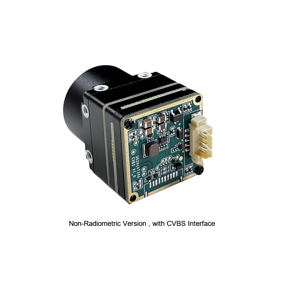
Неохлаждаемый мини 384*288 тепловизионный модуль камеры для дронов
The MINI series infrared thermal imaging module is a compact, high-precision thermal imager designed for direct integration. Featuring a sensitive detector core, stable performance, and essential system interfaces, it fits right into machine vision, drone payloads, automated safety inspections, and equipment monitoring platforms.
Technical Specification Breakdown
| Core Detector Array | 384 × 288 High-Sensitivity Uncooled Microbolometer |
| Video Interface Format | Analog CVBS Output with low-latency signal routing |
| Form Factor & SWaP | Ultra-miniaturized body designed for lightweight airborne gimbals |
| Основные применения | Machine vision, safety inspection, smart manufacturing, drone payloads |

Неохлаждаемый инфракрасный RJ45 CVBS RTSP IP 640*512 тепловизионный сенсорный модуль камеры
Powered by a high-efficiency ASIC processing core, this 640*512 thermal imaging camera module delivers detailed resolution alongside dual RJ45 Ethernet IP and CVBS analog outputs. Built specifically for long-range UAV search-and-rescue, site surveillance, and edge AI video pipelines.
Technical Specification Breakdown
| Core Detector Array | 640 × 512 High-Resolution Uncooled Microbolometer |
| Архитектура обработки | Dedicated Low-Power Hardware ASIC Processing Core |
| Interface Ecosystem | RJ45 Ethernet (RTSP / IP) + Concurrent CVBS Analog Output |
| Основные применения | Enterprise drone systems, edge AI video platforms, long-range SAR |
Master OEM Thermal Module Comparison Matrix
| Product Model | Visual Reference | Разрешение матрицы | Connectivity Profiles | Target Application Focus | Direct Datasheet Link |
|---|---|---|---|---|---|
| Неохлаждаемый мини 384*288 тепловизионный модуль камеры для дронов |
|
384 × 288 пикселей Microbolometer |
• Analog CVBS Output • Compact Pin Headers |
• Lightweight drone gimbals • Smart manufacturing • Machine vision inspection |
Open Specs ➔ |
| Uncooled Infrared RJ45 CVBS RTSP IP 640*512 Thermal Module |
|
640 × 512 пикселей ASIC Engine Core |
• RJ45 IP (RTSP / ONVIF) • Concurrent Analog CVBS |
• High-altitude SAR drones • Automated AI vision analytics • Perimeter monitoring |
Open Specs ➔ |
Оптическая калибровка, NUC и метрики измерения температуры
Getting clean image feeds out of an uncooled тепловизионный модуль takes solid calibration. Microbolometers react constantly to external temperature shifts. Without active image corrections, your video stream will degrade and thermal measurements will drift off target.
Non-Uniformity Correction (NUC) Mechanics
Because micro-fabrication isn't 100% uniform across an array, every single pixel on a microbolometer has slightly different gain and resistance characteristics. Add in internal warmth from driving electronics, and you get fixed-pattern noise (FPN) and vertical streaks across your image if it isn't corrected.
- ⚙️ Mechanical Shutter Calibration (Shutter-Based NUC): The module drops a mechanical shutter flag in front of the array for a fraction of a second, presenting a flat, uniform thermal baseline. The DSP uses this event to reset pixel gain offsets. It works well, but it causes a brief video pause (about 200ms–500ms), which can disrupt auto-tracking algorithms.
- ⚙️ Shutterless Scene-Based NUC Algorithms: Modern modules run intelligent shutterless NUC routines. These mathematical models evaluate scene motion along with internal temperature sensors on the ROIC board to update offset values continuously. You get smooth, uninterrupted video feeds—critical for fast tactical drone operations.
Radiometric Temperature Measurement Math
It's important to differentiate between visual thermal cores (built for high-contrast viewing) and full radiometric temperature measurement engines. Radiometric cores calculate true target surface temperatures across every single pixel by factoring in atmospheric losses and target surface emissivity.
The total heat radiance ($W_{\text{total}}$) picked up by a microbolometer pixel follows the Stefan-Boltzmann radiometric transport model:
Где:
- ⚙️ τ (Tau): Atmospheric transmittance factor along the line-of-sight path.
- ⚙️ ε (Epsilon): Surface emissivity coefficient of the target material (e.g., bare shiny metal $\approx 0.05$, matte paint $\approx 0.95$).
- ⚙️ σ (Sigma): The Stefan-Boltzmann constant ($5.670374 \times 10^{-8} \text{ W/m}^2\text{K}^4$).
- ⚙️ T_target: Absolute target temperature (Kelvin).
- ⚙️ T_ambient: Reflected background temperature (Kelvin).
- ⚙️ T_atmosphere: Ambient air temperature along the path (Kelvin).
By solving this balance equation continuously inside the ASIC firmware, radiometric cores generate accurate temperature readings across changing outdoor conditions. For a broader look at adapting standard camera designs for thermal operation, read our overview on Converting Standard Optical Engines to Thermal Imaging Systems.
Промышленный технический FAQ-справочник
How can I stream video from an IP-enabled thermal imaged module into a custom OpenCV processing pipeline?
Connecting an IP-enabled module—like the Uncooled Infrared RJ45 CVBS RTSP IP 640*512 Module—into a custom computer vision pipeline is straight forward over local network lines. The onboard hardware encoder outputs standard H.264 or H.265 streams accessible via RTSP URIs.
Here is a battle-tested Python setup using OpenCV to pull frames directly into memory:
import cv2

# Module RTSP network endpoint
rtsp_stream_uri = "rtsp://192.168.1.100/live/main"

# Initialize capture stream via FFMPEG backend
cap = cv2.VideoCapture(rtsp_stream_uri, cv2.CAP_FFMPEG)

if not cap.isOpened():
    print("Error: Unable to connect to thermal module stream.")
    exit()

while True:
    ret, frame = cap.read()
    if not ret:
        print("Error: Frame capture failed.")
        break

    # Process thermal frame (e.g., edge detection, target identification)
    gray_thermal = cv2.cvtColor(frame, cv2.COLOR_BGR2GRAY)

    # Render processed thermal frame
    cv2.imshow("OEM Thermal Module RTSP Stream", gray_thermal)

    if cv2.waitKey(1) & 0xFF == ord('q'):
        break

cap.release()
cv2.destroyAllWindows()
If you're running edge analytics, push this script to an embedded platform like an NVIDIA Jetson module mounted right next to the camera core to run real-time target detection models directly on incoming RTSP frames.
What critical criteria dictate thermal core selection for miniature UAV gimbal payloads?
Choosing an OEM thermal engine for lightweight drone gimbals requires balancing four core requirements:
- ⚙️ SWaP Constraints (Size, Weight, Power): Payload weight drops airframe flight times fast. Pick low-power ASIC cores (<1.5W draw) to keep battery drain down and prevent heat build-up inside tight gimbal shells.
- ⚙️ Resolution and Pixel Pitch: For close-up or low-altitude work, a 384×288 array gets the job done cleanly. For higher altitude flights or search-and-rescue work, go with a 640×512 array with 12µm pixel pitch to maintain high spatial detail at a distance.
- ⚙️ Video Latency & Control Interface: Manual piloting needs low delay—use analog CVBS (<10ms) for real-time control. For onboard AI tracking, feed high-resolution RTSP streams straight into your compute hardware.
- ⚙️ Ruggedization: Drone payloads take plenty of shock, vibration, and thermal exposure. Verify the thermal core supports extended operational ranges (-40°C to +80°C) with rigid mounting locations to keep optics aligned under heavy flight loads.
How do radiometric thermal camera modules differ operational-wise from standard thermal imaging cores?
The difference between standard thermal engines and radiometric thermal engines comes down to raw data processing and absolute temperature reporting:
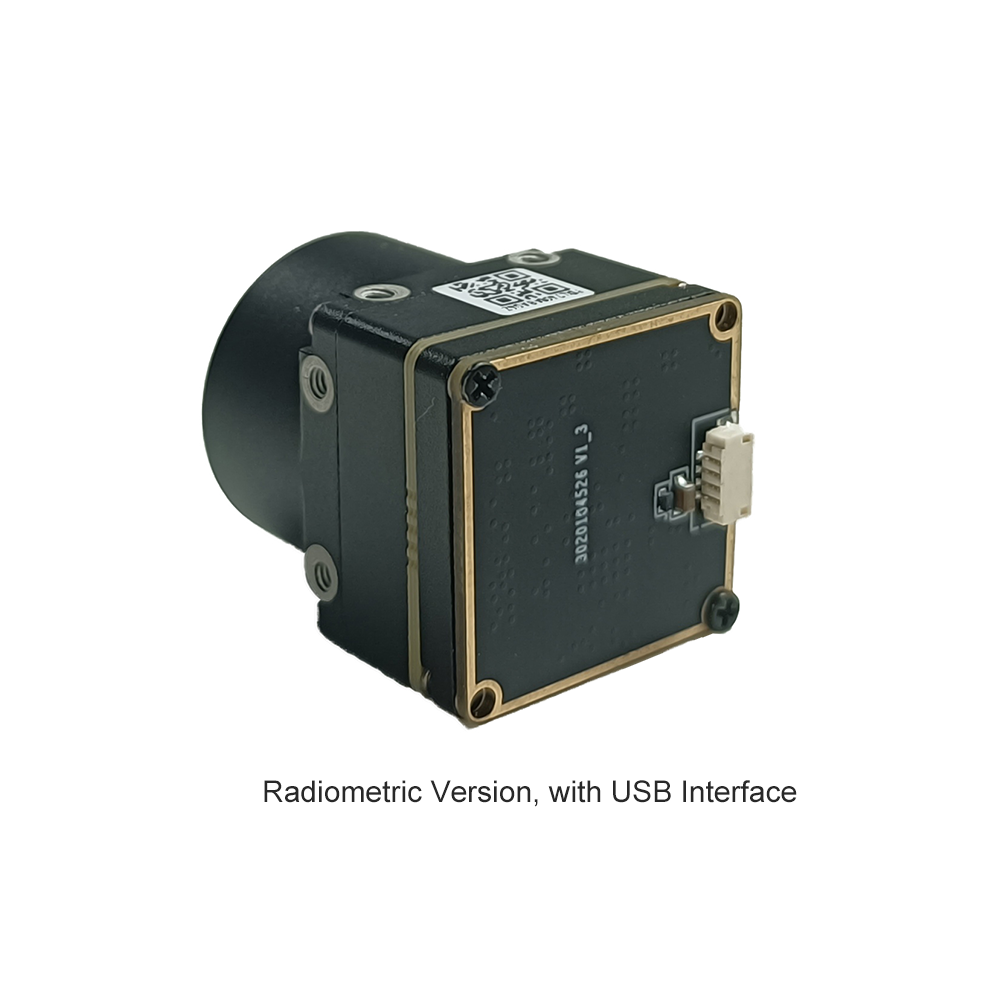
Standard Thermal Camera Modules: These are built purely for image visual quality. They use Automatic Gain Control (AGC) curves to enhance image contrast, making targets pop against colder backgrounds. However, standard cores don't measure calibrated temperature values—pixel brightness simply shows relative heat contrast in the scene.
Radiometric Thermal Camera Modules: Radiometric cores maintain continuous factory and sensor-level thermal calibrations for every pixel on the detector array. By factoring in surface emissivity, distance, atmospheric loss, and ambient humidity, radiometric modules calculate real surface temperatures across the image. That makes them mandatory for utility inspections, solar panel checks, and fire monitoring applications where exact target temperatures are required.
How do optical lens parameters (Focal Length and F-Number) impact thermal range and NETD sensitivity?
The front optics act as the primary light collector, setting strict physical limits on spatial range and system noise:
Focal Length ($f$): Focal length directly dictates field of view (FOV) and optical magnification. Longer focal lengths narrow the view, focusing pixel density on distant targets to boost Detection, Recognition, and Identification (DRI) ranges. But keep in mind: long Germanium lenses add mass and footprint quickly, which can challenge strict SWaP limits.
Lens Aperture ($F$-Number): The $F$-number marks the light-gathering speed of the lens setup. Lower $F$-numbers (e.g., $F/1.0$ vs $F/1.4$) let significantly more infrared energy reach the microbolometer array. Opening up the aperture improves overall system thermal sensitivity (lower effective NETD), providing cleaner frames in low-contrast conditions. For enterprise setups, an $F/1.0$ to $F/1.2$ lens offers the ideal performance balance.
📚 Ссылки и дополнительная литература
- Отраслевой стандарт: OBSETECH Advanced Drone Platform Integrations
- Связанное руководство: LTC Multi-Functional Thermal Module Architecture Analysis
- AI Integration Manual: Top Thermal Camera Modules for UAV AI Processing Systems
- Технический справочник: Adapting Standard Electro-Optical Engines to Infrared Cores