









VOx Uncooled Thermal Imaging Module Buying Guide: Edge AI & OEM Integration
2026年8月20日
Radiometric Thermal Camera Modules: The Ultimate Guide for OEM Industrial Integration
2026年8月21日
LWIR Thermal Camera Modules: Commercial Buyer's Guide to Edge AI & Industrial Thermography
In the field, when you are building autonomous systems for industrial automation, defense robotics, precision ag, or electrical substations, optical vision hits a hard physical wall. Standard CMOS sensors are hostage to ambient lighting, backscatter, dust, and thick marine fog. That is where Long-Wave Infrared (LWIR) sensing changes the game. Operating across the 8 to 14 micrometer (μm) electromagnetic spectrum, uncooled LWIR microbolometer modules do not look for reflected visible light. Instead, they capture emitted thermal radiation straight from the physical objects themselves. This gives your system the ability to see in absolute zero-lux pitch darkness, punch through smoke, and pull exact, pixel-by-pixel surface temperatures across your entire field of view.
Over the last few years, the whole thermal landscape has shifted. We have seen sub-12 μm pixel-pitch focal plane arrays (FPAs) hit commercial scale at the exact moment low-power embedded neural processing units (NPUs) became cheap and fast. You no longer need a bulky, power-hungry industrial computer sitting downstream just to run basic computer vision on thermal data. You can now execute target classification, defect segmentation, and real-world thermography directly at the edge on a micro-gimbal or a remote sensor head.
For optical engineers, systems integrators, and OEM procurement teams, choosing an uncooled LWIR core is a masterclass in trade-offs. You have to constantly balance Size, Weight, Power, and Cost (SWaP-C) against critical radiometric accuracy, modulation transfer function (MTF), and thermal sensitivity. Whether you are packaging an ultra-light payload for an unmanned aerial vehicle (UAV) to locate buried landmines, or installing fixed 1280×1024 thermal eyes on a continuous utility monitoring grid, your mechanical design, optical stack, and calibration routines make or break the system. This engineering guide breaks down the core physics, on-chip processing pipelines, optics, and practical integration hurdles you will encounter on the bench and in the field.
Table of Contents
- 👉 1. Physical Foundations: LWIR (8–14 µm) Waveband Mechanics
- 👉 2. Microbolometer Sensor Architecture & Core Physics
- 👉 3. Edge AI Processing Pipelines in Thermal Vision
- 👉 4. Mission-Critical Industrial & Defense Applications
- 👉 5. Commercial Module Benchmark & Specification Matrix
- 👉 6. Mechanical, Electrical, and SWaP-C Integration
- 👉 7. Deep-Dive Industrial FAQ
1. Physical Foundations: LWIR (8–14 µm) Waveband Mechanics
Thermal imaging in the Long-Wave Infrared spectrum comes down to basic thermodynamics: every single object with a temperature above absolute zero (0 Kelvin / -273.15°C) radiates electromagnetic energy. We calculate this spectral radiant exitance using Planck’s Radiation Law, which details the energy distribution of an ideal blackbody across wavelengths (λ) at thermodynamic temperature (T):
B(λ, T) = (2hc² / λ&sup5;) × [1 / (exp(hc / λkBT) - 1)]
Here, h represents Planck’s constant (6.626 × 10&sup-;³&sup4; J·s), c is the speed of light (2.998 × 10&sup8; m/s), and kB is Boltzmann's constant (1.381 × 10&sup-;²³ J/K). When you integrate this across the entire spectrum, you end up with the Stefan-Boltzmann Law (W = σT&sup4;, with σ ≈ 5.670 × 10&sup-;&sup8; W/m²·K&sup4;), telling us the total energy dumped into the environment scales with the fourth power of absolute temperature.
When you are looking at ambient terrestrial targets and standard machinery operating between -40°C and +150°C (233.15 K to 423.15 K), you need to know where the bulk of that radiant energy lives. Using Wien’s Displacement Law, we find the peak emission wavelength:
λpeak = b / T ≈ 2897.8 μm·K / 300 K ≈ 9.66 μm
Because the bulk of everyday radiation peaks right around 9.6 to 10 μm, the 8 to 14 μm atmospheric transmission window is the sweet spot for uncooled thermal imaging sensors.
Atmospheric Transmission Windows: SWIR, MWIR, and LWIR Compared
The atmosphere is full of water vapor (H2O), carbon dioxide (CO2), ozone (O3), and methane (CH4). These molecules absorb radiation heavily across large swaths of the infrared spectrum. In practical electro-optical engineering, we split thermal and infrared imaging into three distinct operational windows:
- ⚙️ Short-Wave Infrared (SWIR, 0.9–1.7 µm / extended to 2.5 µm): SWIR behaves similarly to visible light, picking up reflected photons instead of thermal emission. You need active illumination, starlight, or nightglow to see anything. SWIR shines in silicon wafer inspection, moisture analysis, and specialized laser tracking.
- ⚙️ Mid-Wave Infrared (MWIR, 3.0–5.0 µm): MWIR detects high-energy photons emitted by extremely hot targets like turbine exhaust, missile plumes, and industrial boilers. Cryogenic Stirling coolers are required to chill these detectors down to ~77 Kelvin (-196°C) to stop internal thermal carrier saturation. That cryogenic engine delivers insane sensitivity, but it burns 15–30W of power, creates acoustic hum, costs a fortune, and wears out mechanically after 8,000 to 15,000 hours of runtime.
- ✅ Long-Wave Infrared (LWIR, 8.0–14.0 µm): LWIR captures the peak blackbody radiation of everyday terrestrial objects. Because uncooled microbolometers run at ambient temperature, they draw very little power (<1.0W to 2.5W), turn on in under 3 seconds, generate zero acoustic noise, and can run for 50,000+ hours without maintenance. For practical, long-term deployments, LWIR is the workhorse of the industry.
Scattering Mechanics in Particulate Environments
Look, one of the biggest reasons engineers deploy LWIR over visible or NIR cameras is pure environmental penetration. When wildfire smoke, factory dust, heavy fog, or airborne oil aerosols blanket a scene, visible sensors go blind. This comes down to the physics of Rayleigh scattering and Mie scattering.
Rayleigh scattering occurs whenever the radius (r) of airborne particles is significantly smaller than the wavelength (λ) of the incoming light (r << λ). The scattering cross-section (σs) scales inversely with the fourth power of the wavelength:
σs ∝ 1 / λ&sup4;
Do the math on this: a visible wavelength is roughly 0.5 μm, while an LWIR wavelength is around 10.0 μm—a 20-fold difference. Raising 20 to the fourth power gives an attenuation reduction factor of 160,000. That means tiny smoke and aerosol particles that completely block visible light are virtually invisible to an LWIR sensor. When water droplets swell up to the size of the wavelength (Mie scattering conditions), LWIR still experiences drastically less signal degradation than visible cameras, keeping your vision feed alive.
Radiometric Temperature Extraction
A true radiometric LWIR core is not just a thermal night vision camera; it is a calibrated, non-contact thermometer for every pixel in your array. The total radiant flux (Wtotal) hitting an individual microbolometer pixel consists of three energy sources: energy emitted by the target, ambient energy reflecting off the target, and path radiance emitted by the air itself:
Wtotal = ε τatm σ Ttarget&sup4; + (1 - ε) τatm σ Trefl&sup4; + (1 - τatm) σ Tatm&sup4;
In this equation, ε is the surface emissivity (0.0 for a shiny mirror, 1.0 for a true blackbody), τatm is atmospheric transmission over distance, Trefl is the reflected background ambient temperature, and Tatm is the air temperature. The onboard DSP runs these calculations continuously on-the-fly, cross-referencing factory-calibrated look-up tables to spit out accurate temperature readings across varying ambient operating conditions.
2. Microbolometer Sensor Architecture & Core Physics
At the center of any modern uncooled LWIR module sits a microbolometer Focal Plane Array (FPA). Unlike cooled photon detectors that rely on quantum bandgap excitation, a microbolometer is fundamentally a thermal resistor network suspended over a silicon Readout Integrated Circuit (ROIC).
Every single pixel is its own microscopic bridge. The absorbing layer—typically silicon nitride (Si3N4) paired with an active resistive film—absorbs incoming 8–14 μm thermal photons. As that membrane heats up, its electrical resistance shifts. Two micro-machined, high-aspect-ratio metal legs hold the bridge suspended over the substrate in a vacuum package. Those legs act as thermal bottlenecks, isolating the pixel so that incoming energy actually heats the membrane instead of instantly leaking into the silicon floor below.
Active Material Composition: Vanadium Oxide (VOx) vs. Amorphous Silicon (a-Si)
The core material of the micro-bridge dictates detector performance, measured primarily by its Temperature Coefficient of Resistance (TCR)—the percentage shift in electrical resistance for every degree Celsius change (α = (1/R) × (dR/dT)):
- ✅ Vanadium Oxide (VOx): VOx is the industry standard for aerospace, defense, and high-end industrial systems. It offers an impressive TCR between -2% and -3% per Kelvin at room temperature, while keeping 1/f flicker noise extremely low. That combination provides cleaner signals, higher signal-to-noise ratios (SNR), and razor-sharp thermal anomaly detection.
- ⚙️ Amorphous Silicon (a-Si): a-Si microbolometers can be manufactured using standard CMOS foundry processes, allowing direct wafer-level integration of the detector membrane right on top of the ROIC. While this lowers unit production costs for high-volume commercial gadgets, a-Si suffers from higher 1/f noise and lower TCR, translating into noticeably lower sensitivity when compared head-to-head with VOx.
Noise Equivalent Temperature Difference (NETD)
When you are evaluating thermal cores on a spec sheet, the absolute most critical number is Noise Equivalent Temperature Difference (NETD), measured in millikelvins (mK). NETD tells you the exact target temperature difference required to produce an electrical output signal equal to the sensor's baseline noise floor (SNR = 1). The formula is defined as:
NETD = (4 F² √Δf) / [Ad × τo × (dV/dT) × D*]
Where F is the optical f-number of the lens, Δf is noise bandwidth, Ad is active pixel area, τo is optical transmittance, dV/dT is detector responsivity, and D* is detectivity.
Here is what that translates to in practical applications:
- ⚙️ Standard Commercial Grade (NETD ≤ 50 mK): Good enough for presence detection, vehicle perimeter tracking, basic HVAC scans, and simple robotic navigation.
- ✅ Precision Industrial / Defense Grade (NETD ≤ 30–40 mK): Required for pinpointing early-stage resistance spikes on high-voltage switchgear, tracking subtle moisture ingress inside roofing structures, surveying buried ordnance via diurnal ground heating changes, and precision gas flare inspections.
Specialized Optical Materials in the LWIR Waveband
Standard optical glass like BK7 or fused silica is essentially an opaque wall to wavelengths beyond 2.5 μm due to heavy multi-phonon absorption. You cannot put a standard glass lens in front of an LWIR microbolometer. Instead, precision optical fabricators like Jinde engineer custom assemblies from specialized infrared substrates:
- ⚙️ Monocrystalline Germanium (Ge): Germanium is the undisputed king of high-performance LWIR optics. Its refractive index is exceptionally high (n ≈ 4.003 at 10 μm), allowing designers to craft fast f/1.0 and f/1.1 optical systems with low spherical aberration in compact lengths. The trade-off is thermal runaway: raw Germanium turns completely opaque above 100°C, and bare surfaces produce significant Fresnel reflections unless treated with high-efficiency Anti-Reflective (AR) or Diamond-Like Carbon (DLC) hard coatings.
- ✅ Chalcogenide Glass (Ge-Sb-Se compounds): Chalcogenide glasses can be precision-molded directly into aspheric and diffractive optical elements at scale. Most importantly, their thermal refractive index shift (dn/dT ≈ +35 × 10&sup-;&sup6;/°C) is roughly ten times lower than Germanium (+396 × 10&sup-;&sup6;/°C). This lets optical engineers build passively athermalized lens housings that maintain pin-sharp focus from -40°C up to +80°C without adding complex mechanical focus motors.
3. Edge AI Processing Pipelines in Thermal Vision
Running modern edge AI models on thermal feeds sounds straightforward until you look at how raw thermal data is structured. Unlike visible cameras that output ready-to-use 8-bit RGB frames based on reflected lighting, an uncooled microbolometer streams single-channel, high-dynamic-range radiometric data (typically 14-bit or 16-bit raw digital counts).
You cannot simply pipe this 14-bit stream directly into an edge neural network like YOLOv8-Thermal or a segmentation model. Without extensive low-level DSP processing, sensor noise and dynamic range compression will destroy your detection accuracy.
Raw Signal Conditioning & Non-Uniformity Correction (NUC)
Because micro-machined bolometer pixels each have microscopic variations in resistance, mass, and gain, an uncalibrated raw thermal frame looks like a wall of static—an artifact known as fixed-pattern noise (FPN). The camera's digital signal processor (DSP) cleans this up via a multi-stage pipeline:
- ⚙️ Bad Pixel Correction (BPC): Dead or non-responsive pixels are mapped during factory calibration and dynamically patched at runtime using neighboring spatial interpolation.
- ⚙️ Two-Point Non-Uniformity Correction (NUC): The DSP applies per-pixel offset and gain arrays across the active matrix:
Scorrected(i,j) = G(i,j) × [Sraw(i,j) - O(i,j)]
Here, G(i,j) is the pixel gain matrix and O(i,j) is the offset matrix, which is re-zeroed periodically by dropping a small mechanical shutter in front of the array for a fraction of a second.
- ✅ Scene-Based Non-Uniformity Correction (SBNUC): For mission-critical tracking where you cannot afford a shutter freeze during flight or robotic movement, modern DSPs run motion-based continuous estimation algorithms to scrub drift out of the frame dynamically without physical shutters.
Dynamic Range Compression & Digital Detail Enhancement (DDE)
Edge inference engines and operator screens generally work on 8-bit inputs (0 to 255 grayscale). If you take a 14-bit raw thermal stream (16,384 discrete levels) and linearly squeeze it into an 8-bit container, low-contrast targets—like a person walking across warm asphalt—disappear into the background noise floor. Modern thermal processors resolve this with two key algorithms:
- ⚙️ Contrast Limited Adaptive Histogram Equalization (CLAHE): Rather than calculating a global histogram, CLAHE works locally across distinct contextual grid tiles, boosting weak local temperature differences while preventing noisy backgrounds from saturating.
- ✅ Digital Detail Enhancement (DDE): This algorithm uses non-linear bilateral spatial filtering to split the thermal image into two distinct bands: a low-frequency base layer (representing overall broad environmental temperature gradients) and a high-frequency detail layer (fine edges, wires, mechanical seams, and subtle textures). The detail layer is amplified and combined back with the compressed base layer, giving neural networks sharp object boundaries to latch onto.
If you are integrating these pipelines onto embedded platforms like a Raspberry Pi or NVIDIA Jetson, smooth performance depends heavily on the underlying Linux video architecture. Review our hands-on walkthrough on Raspberry Pi thermal module driver implementations for configuring V4L2 kernel modules and SPI/I2C communication pipelines. To map out custom bus architectures and OEM hardware pinouts, check our in-depth resource on OEM thermal core integration architectures.
4. Mission-Critical Industrial & Defense Applications
Industrial Predictive Maintenance & High-Voltage Utilities
In heavy manufacturing facilities and electrical utility grids, sudden component failure causes massive operational downtime and catastrophic safety risks. When bolted busbar joints, disconnect switches, breaker terminals, or motor bearings begin to fail, mechanical friction or electrical resistance climbs. Based on Joule’s First Law (P = I²R), that added resistance converts directly into localized heat dissipation well before an arc flash occurs or a bearing seizes up.
Radiometric LWIR modules continuously scan switchgear and high-voltage assets, allowing maintenance automation systems to trigger alerts based on Delta-T (ΔT) criteria:
- ⚙️ 1°C to 10°C Rise Above Ambient/Baseline: Early resistance warning; log for routine inspection during the next maintenance cycle.
- ⚙️ 11°C to 30°C Rise: Serious localized defect; requires corrective maintenance during upcoming planned outages.
- ✅ >30°C Rise Above Baseline: Critical hazard; immediate threat of catastrophic dielectric breakdown or fire. Disconnect immediately.
Autonomous Perimeter Security & Force Protection
Standard visible cameras and active IR illuminators struggle with headlight bloom, tree shadows, camouflage, and adverse weather. Uncooled LWIR cores operate as true passive optical sentinels. System designers calculate perimeter detection limits using the standardized Johnson Criteria, which defines the line pairs required across a target's critical dimension:
- ⚙️ Detection (1.0 ± 0.25 line pairs): Confirming that an object of interest (person, vehicle) is present in the scene.
- ⚙️ Recognition (4.0 ± 0.8 line pairs): Classifying the target type (e.g., separating a human from a stray deer, or a truck from a passenger car).
- ✅ Identification (6.4 ± 1.5 line pairs): High-confidence determination (e.g., distinguishing an armed intruder from an unarmed worker).
To see how multi-spectral thermal payloads integrate into large-scale automated border systems, dive into our technical guide on industrial security thermography frameworks.
UAV Payloads, Humanitarian Demining, and Field Robotics
Mounting ultra-compact LWIR thermal cores on robotic crawlers and aerial drones has modernized unexploded ordnance (UXO) and humanitarian landmine clearance. Buried landmines—including low-metal plastic designs—disrupt the natural compaction, moisture migration, and heat capacity of the soil directly above them.
During morning sunrise and evening sunset cycles—known as thermal crossover periods—the ground right over a buried threat changes temperature at a measurably different rate than the surrounding native soil. Aerial gimbals equipped with high-sensitivity radiometric LWIR modules pick up these tiny surface thermal deviations (ΔT ≤ 0.05°C) from safe standoff altitudes, mapping minefields without risking deminers on the ground.
5. Commercial Module Benchmark & Specification Matrix
Selecting the right LWIR core means aligning your resolution, pixel pitch, thermal sensitivity, optics, and video output protocols directly with your platform constraints. For sourcing high-volume industrial electronics and managing production supply chains, integrators can coordinate directly through certified component suppliers like KUYANG. Below is an engineering overview and specification matrix comparing two benchmark OEM thermal cores.
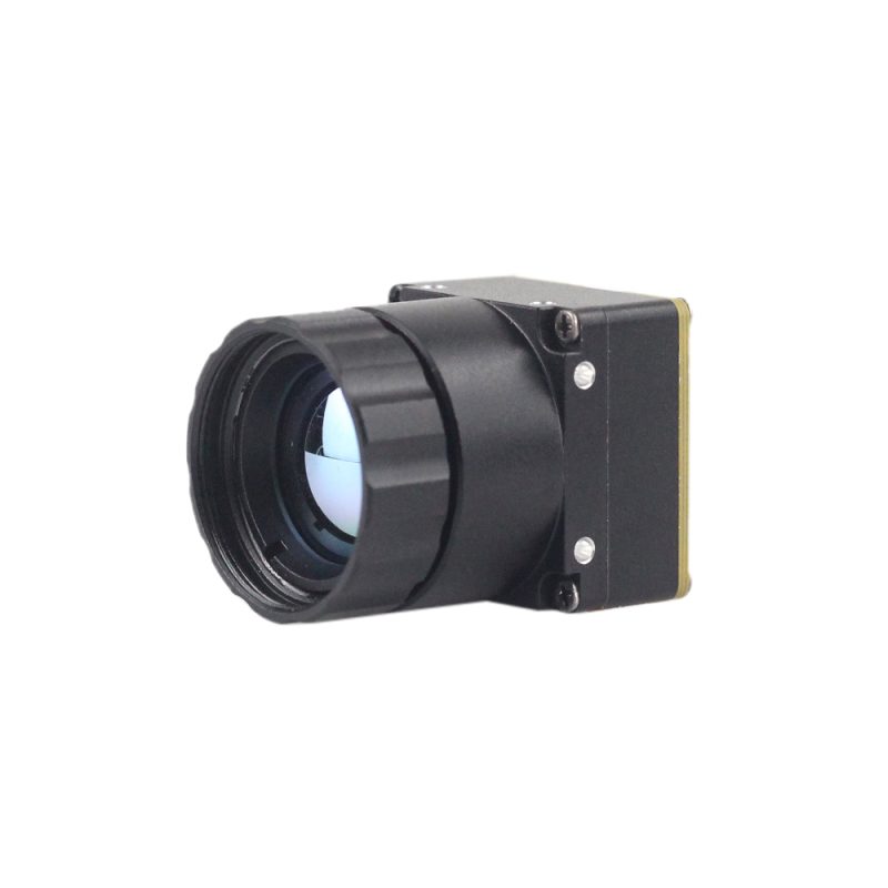
1. Mini 256 Uncooled LWIR Thermal Camera Module
The Mini 256 Uncooled LWIR Thermal Camera Module is an ultra-compact, featherweight thermal engine engineered specifically for micro-gimbals, commercial drone payloads (similar in form factor and mission profile to DJI enterprise platforms for detecting mines), search-and-rescue robotics, and body-worn tactical observation systems. Adopting advanced high-performance infrared detectors, the Mini 256 captures terrestrial infrared radiation and outputs a uniform, ultra-clear thermal image with integrated radiometry for precise temperature measurement.
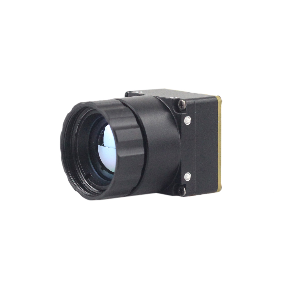
Key architectural characteristics include:
- ✅ High-Sensitivity Microbolometer: Features a 256×192 resolution focal plane array with a 12 μm pixel pitch, delivering sharp spatial resolution while minimizing optical diameter requirements.
- ⚙️ Integrated Radiometric Engine: Captures raw thermal radiation and converts it into accurate, per-pixel temperature measurements, allowing onboard edge systems to detect thermal anomalies automatically.
- ✅ SWaP-Optimized Footprint: Engineered for extreme Size, Weight, and Power (SWaP) constraints, making it directly embeddable into miniature aerial platforms, handheld thermography devices, and robotic mine-clearing crawlers.
- ⚙️ Flexible Output Standards: Supports digital video output protocols (DVP/USB) alongside serial command interfaces for seamless host communication.
2. High Resolution Uncooled Infrared 1280×1024 Thermal Imaging LWIR Camera
For wide-area perimeter defense, high-altitude UAV payloads, and precision electrical substation inspection, the High Resolution Uncooled Infrared 1280×1024 Thermal Imaging LWIR Camera is the benchmark. Pushing true 1.3-megapixel radiometric thermal frames, this core eliminates pixelation and captures minute thermal gradients across massive scenes.
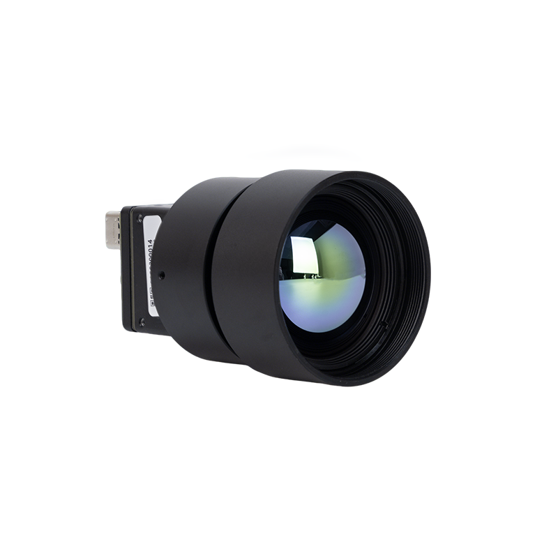
Key architectural characteristics include:
- ✅ Megapixel Thermal Array: Boasts a 1280×1024 detector array (over 1.31 million active radiometric pixels), providing 4.3 times the spatial data of standard VGA (640×512) cores.
- ⚙️ High-Fidelity 25mm Optics: Standard configuration features a precision-machined 25mm athermalized Germanium lens, delivering superior optical throughput and high Instantaneous Field of View (IFOV).
- ✅ Advanced Radiometric Calibration: Factory calibrated across extensive dynamic ranges to deliver accurate temperature readings under extreme environmental operating conditions.
- ⚙️ High-Throughput Digital Interconnects: Engineered with industrial-grade high-speed digital interfaces suitable for direct connection to embedded DSPs, FPGAs, and Edge AI accelerators.
Comprehensive Engineering Specification Benchmark
| Specification Parameter | Mini 256 Uncooled LWIR Module | High Resolution 1280×1024 LWIR Camera |
|---|---|---|
| Detector Resolution | 256 × 192 pixels (49,152 measurement points) | 1280 × 1024 pixels (1,310,720 measurement points) |
| Pixel Pitch | 12 μm | 12 μm |
| Spectral Range | 8.0 to 14.0 μm (LWIR) | 8.0 to 14.0 μm (LWIR) |
| Detector Technology | Uncooled VOx Microbolometer | High-Density Uncooled VOx Microbolometer |
| Thermal Sensitivity (NETD) | ≤ 40–50 mK @ f/1.0, 300 K | ≤ 35–40 mK @ f/1.0, 300 K |
| Frame Rate | 25 Hz / 30 Hz / 50 Hz | 25 Hz / 30 Hz / 50 Hz |
| Standard Lens Configuration | Athermalized micro-optics | 25 mm precision Germanium lens (optional telephoto) |
| Radiometric Calibration | Per-pixel radiometric output (±2°C or ±2%) | Precision full-frame radiometry (±2°C or ±2%) |
| Digital Video Interfaces | DVP, USB 2.0, UART control | Cameralink, USB 3.0, MIPI-CSI-2, Ethernet / GigE |
| Power Consumption | ≤ 0.8 W (ultra-low power consumption) | ≤ 2.5 W (full DSP pipeline active) |
| Primary Target Deployments | Micro-gimbals, UAV demining payloads, SAR drones, handhelds | Fixed utility monitoring, border defense, high-altitude UAVs |
6. Mechanical, Electrical, and SWaP-C Integration
Here's the deal: dropping an uncooled LWIR core into an autonomous vehicle or an industrial pan-tilt-zoom head is not just plug-and-play. You have to treat the sensor as an electro-optical thermal engine with strict mechanical and thermal boundaries.
Thermal Management and Sensor Housing Isolation
While uncooled FPAs do not need cryogenic coolers, the microbolometer works by measuring tiny millikelvin shifts across isolated pixel bridges. If heat from your onboard power supply, motor driver, or edge AI compute board flows unevenly into the camera chassis, the FPA will suffer severe thermal drift. This causes image shading, fixed-pattern noise, and ruined radiometric accuracy.
In the shop, follow these thermal isolation practices:
- ⚙️ Conductive Isolation: Mount your thermal core on low-thermal-conductivity standoffs (such as PEEK or ceramic spacers) to thermally isolate the sensor from adjacent host compute boards.
- ✅ Dedicated Chassis Sinking: Direct heat generated by the module's onboard DSP through dedicated thermal pads out to the external aluminum enclosure, maintaining a stable, uniform temperature across the sensor plane.
- ⚙️ Avoid Direct Forced Air: Never point cooling fan exhaust directly over the exposed lens barrel or bolometer chassis. Uneven, turbulent airflow creates localized temperature fluctuations that throw off radiometric calibration algorithms.
High-Speed Digital Video Interface Architectures
Choosing the right digital interface determines your latency, system complexity, and host processing requirements:
- ⚙️ MIPI-CSI-2 / CMOS DVP: The gold standard for embedded board-to-board designs with SoCs like the NVIDIA Jetson Orin Nano, Rockchip RK3588, or NXP i.MX8. MIPI-CSI-2 transfers uncompressed 14-bit raw radiometric frames straight into host DMA memory with microsecond latency, bypassing USB protocol stacks.
- ✅ USB 3.0 / USB-C (UVC Radiometric Class): Best for industrial PCs, fast bench prototyping, and lab testing. Make sure your module firmware supports USB Video Class (UVC) extensions to transmit synchronized 14-bit radiometric metadata alongside the 8-bit visual stream over a single physical cable.
- ⚙️ GigE Vision / Industrial Ethernet: The standard choice for long-distance factory floor automation. Run uncompressed radiometric feeds up to 100 meters over standard Cat6 cabling straight into centralized industrial servers or PLCs.
Optomechanical Alignment and High-Vibration Ruggedization
When you are working with small 12 μm pixels, optical depth of focus (δ) is razor thin:
δ ≈ 2 × (f/#) × (Pixel Pitch) ≈ 2 × 1.0 × 12 μm = 24 μm
Because your focus tolerance is less than 25 micrometers, any mechanical deformation or thermal expansion in the lens mount will blur the image. On high-vibration drone airframes or stamping press inspection systems, you need fine-pitch locked optical threads (such as M12 or M10 with locking set-screws) combined with aerospace-grade thread-locking adhesives to maintain optical alignment under harsh mechanical shock (MIL-STD-810H standards).
7. Deep-Dive Industrial FAQ
What is the primary practical difference between cooled MWIR and uncooled LWIR thermal cameras?
How do high-resolution 1280×1024 LWIR cores improve predictive maintenance and infrastructure inspection?
Can miniature LWIR camera modules be integrated directly with Edge AI for custom drone mine-detection payloads?
📚 References & Further Reading
- Industry Standard: Precision Infrared Optics Fabrication & Coatings – Jinde Optical Engineering
- Industry Standard: Industrial Electronics & Thermal Component Sourcing – KUYANG Supply Chain Portal
- Related Guide: Multi-Sensor Security Architectures & Thermography Frameworks – Industrial Security Vision Systems
- Related Guide: Comprehensive OEM Core Hardware & Protocol Integration – Thermal Module Integration Guide
- Related Guide: Embedded Thermal Camera Driver Configuration – Raspberry Pi RS300 Thermal Driver Setup





