








LWIR Thermal Camera Modules: Commercial Buyer's Guide to Edge AI & Industrial Thermography
2026年8月21日
CMOS Sensor Selection & Integration: Commercial Sourcing Guide for AI & Thermal Vision Systems
2026年8月24日
Radiometric Thermal Camera Modules: The Ultimate Guide for OEM Industrial Integration
Look, if you've spent any time designing machine vision rigs, autonomous mobile robots (AMRs), or tactical drone gimbals, you already know the harsh truth: qualitative thermal imaging just doesn't cut it anymore. Pretty false-color heat maps look great on a marketing brochure, but when an automated system has to make a split-second go/no-go call on a failing utility transformer or spot thermal runaway in a battery pack, relative contrast is useless. You need hard, calibrated temperature data across every single pixel on that focal plane array. That is the exact difference between an uncalibrated optical novelty and an industrial-grade radiometric thermal camera module.
Building a radiometric core into an OEM product is no walk in the park. You're balancing sensor physics, microbolometer thermal drift, tight Size, Weight, and Power (SWaP) budgets, and noisy digital interfaces like MIPI-CSI2 or USB 3.0. When your sensor die drops to a 12μm pixel pitch or smaller, keeping a tight ±2°C accuracy spec across varying ambient temperatures will test even the sharpest electrical and optical engineering teams. In this guide, we'll strip away the high-level marketing speak and dig straight into the brass tacks of hardware architectures, calibration algorithms, real-world edge AI interfacing, and core OEM selection.
Table of Contents
- 👉 1. Demystifying Radiometric vs. Qualitative Thermal Imaging
- 👉 2. Uncooled Microbolometer Core Hardware & Sensor Architecture
- 👉 3. Edge AI Processing, Machine Vision, and Drone Payloads
- 👉 4. OEM Product Showcase & Technical Comparison Matrix
- 👉 5. Radiometric Calibration, Drift Compensation, and Environmental Optics
- 👉 6. Systems Integration, Protocols, and Deployment Strategies
- 👉 7. Deep-Dive Frequently Asked Questions (FAQ)
1. Demystifying Radiometric vs. Qualitative Thermal Imaging
Let's clear up a common misconception upfront. Standard non-radiometric infrared cameras only care about visual scene contrast. They take long-wave infrared (LWIR) photon flux in the 8 to 14 μm range, let the microbolometer spit out raw resistance values, and then hammer that raw feed with dynamic Automatic Gain Control (AGC) and tone mapping. The result? A clean, 8-bit video feed using color palettes like Ironbow or White Hot. The catch is that those 8-bit grayscale values (0 to 255) are completely floating. If a hot exhaust pipe enters the frame, the entire image shifts its tone mapping to prevent clipping, and your background pixel values change completely—even if the actual temperatures didn't budge a fraction of a degree.
True radiometric thermal camera modules operate on an entirely different level. Instead of a squashed 8-bit visual feed, a radiometric core outputs an uncompressed, linear 14-bit or 16-bit digital matrix where every coordinate (X, Y) maps straight to an absolute physical temperature value—usually in centikelvin (cK) or tenths of a degree Celsius. The core handles the heavy math governed by Planck's law and the Stefan-Boltzmann law directly on its onboard processing engine. As laid out in foundational physics literature on Wikipedia Thermal Imaging, calculating calibrated temperature demands continuous compensation for surface emissivity, atmospheric transmission loss, ambient reflected energy, and the internal thermal signature of the camera assembly itself.
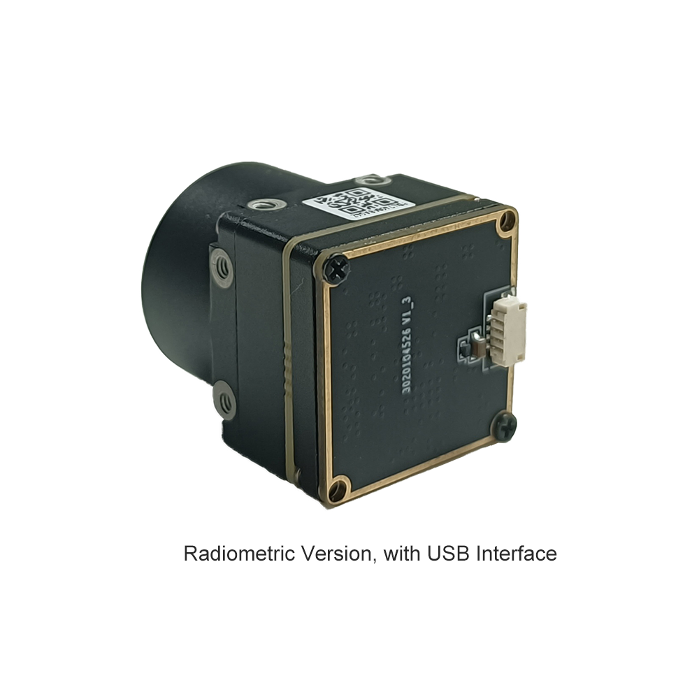
When you wire a radiometric module into an embedded computing host, you bypass dynamic contrast guesswork. Your software can directly query coordinate (320, 240), pull an integer value like 31815, and know immediately that the target is sitting at 318.15 Kelvin (45.0°C). That raw, deterministic numeric stream is what powers real-time safety shutoffs, automated weld quality inspections, and early-warning fire alarms.
The Physics of Pixel-Level Accuracy and NETD
When evaluating radiometric datasheets, Noise Equivalent Temperature Difference (NETD) is the primary metric to watch. Measured in millikelvins (mK), NETD defines the lowest thermal delta the detector can resolve before signals get lost in the electronic noise floor. Here's what you need to keep in mind when spec'ing a core:
- ⚙️ Sensor Noise Floor (<40 mK vs. <50 mK): A sub-40 mK core (tested at f/1.0 and 300K) resolves temperature deltas as tiny as 0.04°C. In predictive maintenance, that added sensitivity lets you spot high-resistance electrical connections or failing mechanical bearings weeks before thermal runaway occurs.
- ⚙️ Aperture Matching Matters: Never evaluate NETD in a vacuum. A sensor rated at 35 mK behind an f/1.0 lens will degrade to nearly 70 mK if you swap in a slower f/1.4 lens to cut optical costs. Match your optics to your application's thermal budget.
- ⚙️ Signal-to-Noise Ratio (SNR) for Edge AI: Edge machine learning models rely on clean pixel gradients. High sensor noise creates high-frequency spatial artifacts that trigger false edge detections and ruin temperature threshold tracking.
2. Uncooled Microbolometer Core Hardware & Sensor Architecture
For 99% of commercial and industrial OEM designs, uncooled microbolometer Focal Plane Arrays (FPAs) are the clear choice over cryogenically cooled Stirling engine systems. Cryocooled sensors are fantastic for long-range defense targeting, but their high cost, bulk, and 8,000-hour cooler lifespans make them impractical for standard industrial hardware. Uncooled microbolometers run at ambient temperature, sip power, and offer Mean Time Between Failures (MTBF) exceeding decades.
In the microbolometer world, the battle comes down to Vanadium Oxide (VOx) versus Amorphous Silicon (α-Si). In our engineering lab, VOx wins out almost every time for industrial radiometry. VOx delivers a significantly higher Temperature Coefficient of Resistance (TCR, around 2% to 3%/K) and lower 1/f flicker noise compared to α-Si. Each pixel on a VOx FPA is an ultra-thin absorbing bridge suspended over silicon substrate legs in a vacuum package. When LWIR radiation hits that bridge, its resistance shifts, and the Readout Integrated Circuit (ROIC) converts that analog voltage shift into a digital number via high-speed on-chip ADCs.
The 12μm Pixel Pitch Revolution & SWaP Optimization
Over the past few years, wafer-level packaging (WLP) has driven pixel pitches down from 25μm and 17μm to 12μm and even 10μm. For hardware engineers building space-constrained products, this shrink is a game changer:
- ✅ Dramatically Smaller Optics: Optical physics dictates that a smaller pixel pitch requires a shorter focal length lens to cover the exact same Instantaneous Field of View (IFOV). A 12μm 640×512 core can use a lens that is nearly half the size and weight of a 17μm equivalent, taking substantial bulk out of drone gimbals and handheld housings.
- ✅ Lower Power Dissipation: Smaller silicon dies draw less power during ROIC readout cycles. Many modern 12μm modules operate comfortably under 1.2W to 1.5W, simplifying thermal heat-sinking on sealed IP67 enclosures.
- ✅ Massive Pixel Density: You get 327,680 individual measurement probes packed into an active area barely larger than a pencil eraser, giving your software exceptional spatial granularity.
ASIC Signal Processing and Non-Uniformity Correction (NUC)
Microbolometers are naturally imperfect. Raw silicon comes out of the fab with pixel-to-pixel gain variations, dark current offsets, and fixed-pattern noise (FPN). To transform that raw sensor noise into clean radiometric data, modern modules incorporate dedicated onboard Application-Specific Integrated Circuits (ASICs). The ASIC performs real-time corrections on the fly:
- ⚙️ Mechanical Shutter Non-Uniformity Correction (NUC): A small solenoid drops a uniform temperature shutter blade across the sensor path for a fraction of a second. The ASIC samples this flat field, recalculates pixel offset tables, and zeroes out spatial drift.
- ⚙️ Shutterless Scene-Based NUC (SBNUC): For high-speed industrial lines or tactical UAVs where an image freeze could disrupt tracking, smart algorithms monitor scene motion and dynamically calculate NUC tables without dropping the mechanical shutter.
- ⚙️ Dynamic Bad Pixel Replacement (BPR): Pixels that drift out of factory noise tolerances are dynamically tagged and interpolated using neighboring pixel matrices, preventing dead-pixel artifacts from triggering false alarms.
3. Edge AI Processing, Machine Vision, and Drone Payloads
Industrial automation is rapidly moving away from centralized servers toward edge AI processors like the NVIDIA Jetson Orin, Rockchip RK3588, and NXP i.MX8 platforms. Standard RGB machine vision identifies objects by edge gradients and color features, but it fails in total darkness, smoke, or when trying to detect internal component stress. Pairing raw 14-bit radiometric data with modern edge AI creates an extremely resilient multi-modal perception system.
If you're designing a compute architecture from scratch, check out this practical guide on choosing industrial thermal camera modules for edge AI. The optimal integration strategy involves running a dual-stream data pipeline:
- ⚙️ The 8-Bit Inference Stream: The module or host ISP maps the raw data to an 8-bit visual stream (YUV/RGB) running through a YOLOv8 or semantic segmentation model. The AI localizes bounding boxes around critical targets—such as pump housings, motor bearings, or electrical insulators.
- ⚙️ The 14-Bit Direct Radiometric Buffer: In parallel, the host memory maintains an uncompressed Y14/Y16 direct radiometric memory buffer via Direct Memory Access (DMA). When the neural network detects an asset bounding box, your business logic reads the exact raw temperature values within those precise coordinates.
When mounting radiometric cores on aerial drone payloads, environmental challenges escalate. UAVs face high-frequency motor vibration, rapid altitude changes, and continuous prop-wash airflow that can cool down the camera housing unevenly. Radiometric tracking under these conditions demands robust mechanical isolation and tightly tuned firmware filters. To see how these systems perform in practice, take a look at this drone thermal imaging video demonstration highlighting real-time radiometric tracking and gimbal stabilization under high-speed flight conditions.
4. OEM Product Showcase & Technical Comparison Matrix
Picking the right radiometric core comes down to balancing raw resolution, interface protocols, physical footprint, and driver support against your project's development schedule. Here are two field-proven OEM thermal camera modules built specifically for demanding industrial integrations.
Uncooled Infrared RJ45 CVBS RTSP IP 640*512 Thermal Sensor Camera Module

Designed specifically for networked industrial monitoring, perimeter security, and high-performance drone payloads, this uncooled infrared mini 640×512 ASIC thermal imaging camera module provides high spatial resolution combined with versatile network streaming capabilities. Featuring an onboard hardware ASIC processing engine, it handles non-uniformity correction, digital filtering, and radiometric temperature conversion directly on the module.
- ✅ Detector Core: 640×512 uncooled VOx microbolometer focal plane array
- ✅ Interfaces: RJ45 Ethernet (IP network streaming), RTSP video stream, CVBS analog video
- ✅ Processing Architecture: Onboard ASIC thermal processing engine for low-latency analytics
- ✅ Primary Target Systems: Airborne drone gimbals, smart industrial surveillance, substation monitoring
MD Series 384x288 Uncooled Infrared Thermal Camera Module
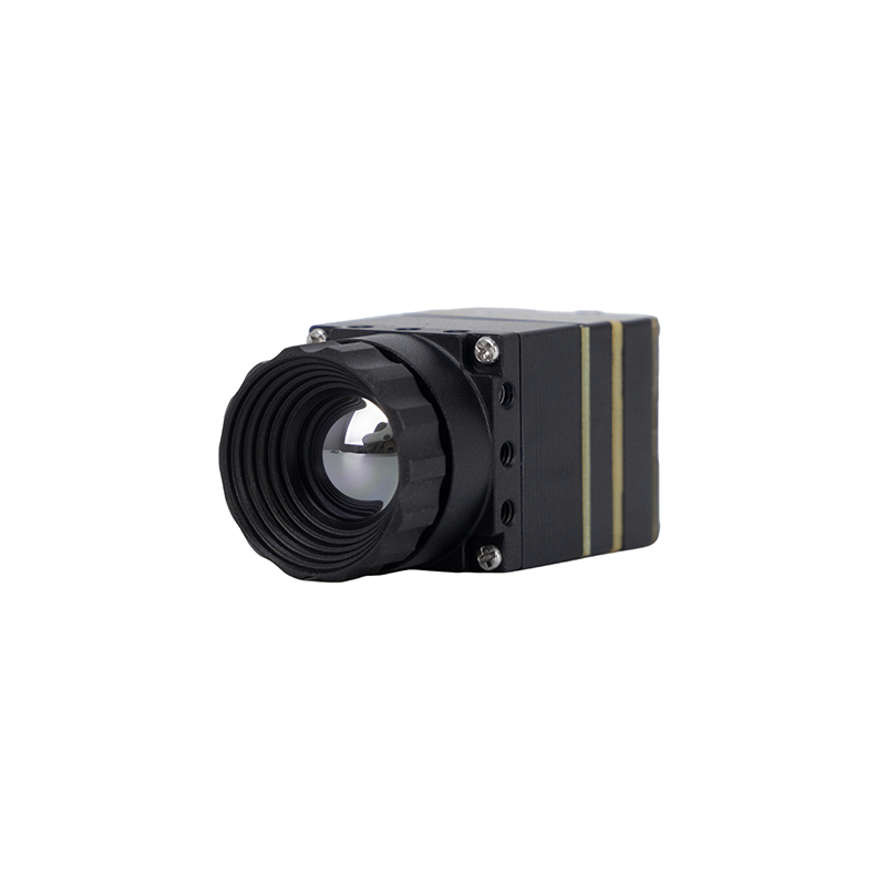
The Purpleriver MD Series thermal camera module is engineered for industrial-grade precision across security, temperature monitoring, and drone integration. Utilizing an uncooled infrared detector with a modern 12μm pixel pitch, it delivers high sensitivity, rapid thermal response, and sharp radiometric imaging within an ultra-compact footprint. Featuring plug-and-play functionality across MIPI, USB, and CVBS interfaces, the core allows direct embedded integration into edge AI compute boards. Backed by an engineering team with Hong Kong University of Science and Technology (HKUST) academic pedigree and former Huawei HiSilicon semiconductor expertise, this module offers comprehensive OEM/ODM hardware and firmware customization.
- ✅ Detector Resolution: 384×288 uncooled microbolometer detector
- ✅ Pixel Pitch: 12μm high-density wafer-level package
- ✅ Hardware Interfaces: MIPI CSI-2, USB Type-C / USB 2.0, CVBS analog
- ✅ Engineering Heritage: HKUST R&D background & former Huawei HiSilicon chip design team
- ✅ Target OEM Applications: Embedded robotics, handheld thermography, condition monitoring, edge AI
| Hardware Feature | 640×512 RJ45/RTSP ASIC Module | MD Series 384×288 12μm Module |
|---|---|---|
| Array Resolution | 640 × 512 pixels | 384 × 288 pixels |
| Pixel Pitch | Standard microbolometer pitch | 12μm high-density microbolometer |
| Physical Interfaces | RJ45 Ethernet, CVBS Analog | MIPI CSI-2, USB 2.0/3.0 Type-C, CVBS |
| Streaming Protocols | RTSP / IP Video, ONVIF, Raw Socket | Direct MIPI Raw Y14/Y16, UVC Stream |
| Processing Engine | Dedicated Onboard ASIC Processor | Embedded Low-Power ISP / SDK Bridge |
| Form Factor Focus | Drone Payload, Networked Enclosure | Ultra-Compact SWaP Embedded Board |
| Customization Capability | Standard Network & Optics Config | Full OEM/ODM Hardware & Driver Tailoring |
5. Radiometric Calibration, Drift Compensation, and Environmental Optics
In the shop, holding a ±2°C or ±2% accuracy rating over a wide industrial temperature range (-20°C to +60°C ambient) is one of the toughest challenges you'll face. An uncooled microbolometer doesn't just see the target; it sees its own mechanical enclosure, the internal PCB heat dissipation, and the optical lens barrel. As your system warms up, internal parasitic infrared radiation floods the sensor array, causing significant temperature drift if your firmware isn't actively compensating for it.
To keep readings stable, industrial modules use a network of Negative Temperature Coefficient (NTC) thermistors placed at critical internal thermal nodes:
- ⚙️ FPA Die Thermistor: Tracks the microbolometer substrate temperature directly to adjust raw bridge bias voltages.
- ⚙️ Lens Housing Thermistor: Measures thermal expansion and infrared self-emission from the Germanium or chalcogenide lens assembly.
- ⚙️ Ambient Mainboard Thermistor: Monitors thermal build-up generated by the local power supply regulators and processing ASICs.
During factory calibration, the module sits in an environmental thermal chamber exposed to traceable blackbody cavities across multiple temperature steps. Multi-dimensional polynomial surface matrices are calculated and flashed directly into the module's non-volatile EEPROM. In the field, the onboard processor pulls real-time thermistor values and dynamically shifts the calibration curves to deliver accurate, repeatable measurements.
Infrared Optics and Anti-Reflective Coatings
Standard borosilicate optical glass is opaque to LWIR photons. Radiometric modules demand specialized optical elements machined from single-crystal Germanium (Ge) or chalcogenide glass alloys. Precision optics manufacturing, like that engineered by Rising Optics, provides the high optical transmission and minimal wavefront distortion required for sharp radiometric mapping. Front elements are treated with Diamond-Like Carbon (DLC) or heavy-duty Anti-Reflective (AR) coatings to resist abrasive dust, industrial chemical vapors, and moisture, maintaining high transmission efficiency across the entire 8 to 14 μm band.
6. Systems Integration, Protocols, and Deployment Strategies
When integrating a radiometric camera core into your hardware stack, picking the right bus interface determines your achievable latency, bandwidth overhead, and software development timeline:
- ⚙️ MIPI CSI-2 Bus (The Embedded Standard): Direct connection to the host SoC's camera serial interface. Streams uncompressed 14-bit frames straight into Linux Video4Linux2 (V4L2) buffers via DMA with sub-10ms glass-to-glass latency. Ideal for closed-loop robotics, tactical tracking, and tight gimbal packaging.
- ⚙️ USB 3.0 / USB Video Class (UVC): Provides plug-and-play simplicity on industrial x86 PCs and Linux edge gateways. The core pushes standard UVC video on one endpoint and streams uncompressed 16-bit radiometric raw frames over a bulk USB pipe.
- ⚙️ Networked IP / RTSP / ONVIF: Best suited for long-run infrastructure installations, plant floor monitoring, and substation security. Encodes H.264/H.265 video with radiometric temperature metadata packed into ONVIF extensions or streamed over parallel TCP/UDP sockets.
For engineering teams targeting European or global industrial automation markets, reviewing region-specific standards—such as this technical przewodnik wyboru czujnika termicznego OEM AI—ensures full compliance with CE EMC requirements, RoHS standards, and industrial fieldbus protocols before you spin your final circuit board revisions.

7. Deep-Dive Frequently Asked Questions (FAQ)
What is the fundamental difference between standard thermal imaging and radiometric thermal measurement?
How do compact thermal camera modules maintain radiometric accuracy during ambient temperature swings?
How does radiometric bit depth impact edge AI analytics and automated fault detection?
📚 References & Further Reading
- Industry Standard: Wikipedia Thermal Imaging & Radiometric Infrared Principles
- Precision Optics: Rising Optics Infrared Optical Assemblies & AR Coatings
- Related Guide: How to Choose the Right Industrial Thermal Camera Module for AI Edge
- Related Guide: Przemyslowy Przewodnik Wyboru Czujnika Termicznego OEM AI Moduly Kamer B2B
- Related Guide: Video Demonstration: Thermal Imaging Camera Module Integration with Drones





