








Lightweight Thermal Camera Solutions: Compact LWIR Modules for Drones & Edge AI
2026年9月1日
Best Thermal Camera Module Supplier: OEM High-Res Cores for Drones & Edge AI
2026年9月2日
OEM Thermal Camera Module Selection & Integration Guide: Custom IR Cores for Drones & Machine Vision
Modern industrial automation, autonomous robotics, and unmanned aerial vehicles (UAVs) increasingly demand long-wave infrared (LWIR) sensing capabilities integrated directly into size, weight, and power (SWaP)-constrained edge architectures. Designing next-generation optical payloads means stepping away from heavy, self-contained thermal cameras and moving straight to compact, board-level OEM thermal camera modules. These bare microbolometer cores hand hardware engineers and system architects direct access to high-speed digital video pipelines (like MIPI-CSI2 and raw USB bulk transfers), uncompressed 14-bit radiometric pixel arrays, and bare-metal register controls. But getting an infrared core to perform reliably out in the field isn't just plug-and-play. It involves real trade-offs between solid-state physics, pixel geometry, thermal sensitivity (NETD), optical throughput, radiometric scene calibration, and host compute budgets.
Look, when you're piecing together an edge vision payload or an airborne gimbal, sensor-level decisions dictate your entire system's flight dynamic and computer vision pipeline. A poorly calculated thermal dissipation path will trigger thermal drift across the microbolometer die, ruining radiometric precision during critical utility inspections. In the same vein, a sloppy interface bridge introduces dropped frames and transport lag that can bring high-speed collision-avoidance loops to a crawl. This comprehensive engineering guide breaks down the core architecture, electrical routing, lens physics, and software integration of industrial OEM thermal camera modules, giving you field-tested blueprints for drone payloads, automated optical inspection (AOI) rigs, and intelligent edge monitoring systems.
Table of Contents
- 👉 1. Core Microbolometer Architecture & Detector Physics
- 👉 2. Embedded Hardware Interfaces & Digital Video Pipelines
- 👉 3. SWaP-C Optimization for Drone Payloads & Mobile Robotics
- 👉 4. Radiometric Calibration, Temperature Extraction & Edge Analytics
- 👉 5. Industrial OEM Thermal Camera Module Matrix & Showcase
- 👉 6. Custom OEM/ODM Engineering Lifecycle & Firmware Tuning
- 👉 7. Deep-Dive Industrial Engineering FAQ
1. Core Microbolometer Architecture & Detector Physics
An OEM thermal camera module captures long-wave infrared energy across the 8 μm to 14 μm spectral window and converts it into temperature grids or visual heatmaps without needing bulky cryogenic Stirling coolers. The heart of the unit is an uncooled microbolometer: a focal plane array (FPA) made of micro-machined bridge pixels suspended right above a silicon Readout Integrated Circuit (ROIC). Each pixel absorbs incoming infrared light, heating its sensing membrane and changing its internal electrical resistance. If you want to specify the right payload, you have to understand the solid-state materials and physical layouts that govern these sensors.

Microbolometer Material Science: Vanadium Oxide (VOx) vs. Amorphous Silicon (a-Si)
Here's the deal with detector materials: what you coat that micro-bridge with sets your baseline sensitivity, electronic noise floor, and operational stability. Modern industrial cores rely on two primary materials:
- ⚙️ Vanadium Oxide (VOx): VOx is the benchmark in industrial thermography and aerospace platforms for good reason. It delivers a high Temperature Coefficient of Resistance (TCR), sitting comfortably between -2%/K and -3%/K at room temperature, while keeping 1/f electrical flicker noise extremely low. Because of this, VOx microbolometers achieve superior Noise Equivalent Temperature Differences (NETD) and cleaner Signal-to-Noise Ratios (SNR). That extra sensitivity is what allows an inspection drone to spot subtle thermal gradients like early-stage bearing friction or subsurface composite delamination in aerospace skins.
- ⚙️ Amorphous Silicon (a-Si): While a-Si sensors are easier to manufacture on standard CMOS lines—which helps keep unit costs down in high-volume consumer gadgets—they come with lower TCR and higher electronic noise. On top of that, a-Si arrays carry longer thermal time constants. In practical terms, that means you can get noticeable image smearing during fast drone yaw maneuvers or rapid factory conveyor tracking.
Pixel Pitch Evolution: 12μm vs. 17μm Architectures
The industry has shifted away from legacy 17 μm sensors in favor of dense 12 μm wafer-level packaged (WLP) microbolometers. In the shop, this shrink in pixel geometry changes everything about optical design, mechanical balance, and payload physics:
- ✅ Optics Miniaturization: For a given array size (like 384×288 or 640×512), switching to a 12 μm pitch cuts the physical die area of the active sensor by almost 30% compared to a 17 μm chip. That means you need a much shorter focal length lens to hold the exact same Field of View (FOV).
- ✅ Mass & Gimbal Inertia Reduction: Because optical element diameter scales directly with focal length to maintain the target F-number (aperture), the physical volume and weight of the precision Germanium glass drops by 40% to 50%. This mass reduction radically cuts down dynamic gimbal inertia, keeping brushless motors cool and running tight stabilization loops. Integrators modernizing legacy payloads can look into modernizing to compact LWIR cores to maximize thermal performance inside tighter enclosures.
- ⚙️ Modulation Transfer Function (MTF) Requirements: A smaller pixel pitch demands much tighter lens tolerances. To prevent soft edges and loss of contrast, your optical element's MTF has to match the higher Nyquist spatial frequency of a 12 μm pixel array (41.67 lp/mm for 12 μm vs. 29.41 lp/mm for 17 μm). High-purity Germanium or chalcogenide elements with multi-layer anti-reflective coatings are mandatory here.
Thermal Sensitivity (NETD) and Dynamic Range Calibration
Noise Equivalent Temperature Difference (NETD) tells you the minimum temperature change on a target needed to generate a signal equal to the sensor's baseline noise. Measured in millikelvins (mK), lower numbers mean cleaner data and finer thermal resolution:
- ✅ High-Sensitivity Tier (NETD ≤ 40 mK): Essential for long-range search and rescue, gas leak visualization, building envelope energy auditing, and precision crop health indexing where target temperatures only drift fractions of a degree from the ambient background.
- ✅ Standard Industrial Tier (NETD ≤ 50 mK): Plenty capable for high-voltage substation switchgear inspections, manufacturing process automation, molten metal tracking, and robotic welding diagnostics.
Covering low-contrast scenes while handling blistering hot targets requires dual-gain calibration switching. In high-gain mode, the core configures the ROIC integration capacitors to pull out tiny thermal variations between -20°C and +150°C. In low-gain mode, the core throttles integration capacitance to keep the pixels from saturating, expanding the ceiling up to +550°C (or well past +1500°C using custom optical attenuation filters) for foundry, firefighting, and industrial flare-stack monitoring.
2. Embedded Hardware Interfaces & Digital Video Pipelines
The electrical bus you pick on an OEM thermal core dictates your pipeline latency, CPU overhead, and board routing complexity. Hardware engineers need to match the core's output directly to the host architecture—whether running bare microcontrollers, Linux single-board computers, or heavy edge AI accelerators.
MIPI-CSI2 Low-Latency Routing for Edge AI SoCs
When wiring directly into embedded processors like the NVIDIA Jetson Orin, Rockchip RK3588, or NXP i.MX8 families, Mobile Industry Processor Interface (MIPI) CSI-2 is the hands-down standard:
- ⚙️ Direct DMA Memory Access: MIPI-CSI2 pumps raw pixel data over high-speed D-PHY physical lanes straight into the host processor's Video Input (VI) subsystem and Direct Memory Access (DMA) ring buffers. This sidesteps kernel-to-userspace memory copying and wipes out USB stack overhead entirely.
- ⚙️ Sub-15ms Latency: Latency across a 2-lane or 4-lane MIPI link runs well under 10 ms to 15 ms, making it ideal for closed-loop flight obstacle avoidance, fast target tracking, and high-speed sorting arms. For a deeper look at drone integration architectures, review our engineering brief on MIPI thermal camera modules for UAV systems.
- ⚙️ High-Speed PCB Routing Rules: Keep your MIPI differential pairs tightly coupled with 100 Ω ± 10% differential impedance, hold intra-pair skew under 0.15 mm, and maintain an unbroken ground reference plane right beneath the traces to prevent high-frequency clock harmonics from stomping on GPS/GNSS receivers or 2.4/5.8 GHz telemetry links.
USB 2.0 / UVC & Bulk Pipelines for Rapid Prototyping
Universal Video Class (UVC) over USB 2.0 or USB 3.0 gives you instant cross-platform connectivity across industrial PCs, Linux single-board computers like Raspberry Pi, and standard test benches:
- ✅ Dual-Stream Architecture: Industrial cores split the USB pipeline into two endpoints: a standard isochronous UVC stream pumping out 8-bit colorized thermograms (YUV422 or RGB24) for local operator displays, and a parallel bulk endpoint (or virtual COM CDC-ACM port) pushing full 14-bit radiometric raw pixel arrays alongside frame metadata.
- ✅ Zero Custom Drivers: Built straight against Linux V4L2 and Windows Media Foundation backends, USB cores let your software team develop computer vision scripts without having to compile custom kernel-level device drivers first.
Analog CVBS Composite Video for Tactical FPV & Long-Range Downlinks
Analog CVBS (75 Ω) composite video might seem old-school, but in tactical drones and FPV search platforms, it's irreplaceable. Hooking an uncompressed NTSC/PAL line straight into a 5.8 GHz analog video transmitter (VTX) delivers instantaneous, zero-latency situational awareness directly to ground station monitors. Best of all, it operates completely independent of the flight controller's CPU, giving pilots an indestructible visual lifeline if the digital autonomy stack ever locks up.
3. SWaP-C Optimization for Drone Payloads & Mobile Robotics
Every aerial platform and autonomous rover operates under harsh Size, Weight, Power, and Cost (SWaP-C) limitations. Getting an OEM thermal camera module to survive and perform on a moving vehicle requires strict attention to mechanical packaging, thermal drift management, and power filtering.
Mechanical Mass Reduction & Gimbal Balancing
Every single gram on a drone payload eats into flight time and pushes motor draw higher. Modern ultra-compact cores, like the MD Series 384x288 low-power thermal module, tip the scales at under 15 grams (core only) and fit snugly inside 25 mm brushless gimbal housings. Keeping the camera's center of gravity (CG) centered along both optical and mechanical pitch/yaw axes prevents brushless gimbal motors from working overtime, eliminating motor saturation and micro-jitter during aggressive flight paths.
Shutter vs. Shutterless Non-Uniformity Correction (NUC)
As ambient temperatures swing and onboard electronics heat up, microbolometer pixels drift independently, creating Fixed-Pattern Noise (FPN) across your video. Bringing the image back to a clean baseline requires Non-Uniformity Correction (NUC):
- ⚙️ Mechanical Shutter NUC: A tiny internal solenoid drops a uniform calibration flag in front of the array for 200 ms to 500 ms to reset pixel offsets. It's dead accurate, but that momentary freeze can blind optical tracking algorithms or disrupt automated flight controls at the worst possible second.
- ✅ Algorithmic Shutterless NUC: Advanced cores run continuous scene-motion analysis and real-time internal temperature models to calibrate gain and offset coefficients on the fly without a physical blade. This cuts out mechanical moving parts entirely, laughs off high vibration environments, and keeps video streams completely continuous for AI tracking.
Power Integrity & EMI Mitigation in Brushless Motor Systems
Drone power rails are notoriously noisy environments. High-amp switching from Electronic Speed Controllers (ESCs) and brushless motors can easily dump 40V+ inductive spikes and heavy ripple back onto your power plane. Clean up your integration with these field-tested practices:
- ⚙️ Dedicated Power Regulation: Never run your thermal core directly off battery rails. Use a dedicated low-noise LDO regulator or an isolated buck converter filtered with an LC pi-network and fast-acting Transient Voltage Suppression (TVS) diodes.
- ⚙️ Faraday Shielding: High-gain microbolometer ROIC amplifiers easily pick up electromagnetic hash from motor phase wires. House your core inside a precision CNC-machined 6061 aluminum housing to lock in structural rigidity and create a solid Faraday cage against RF interference.
- ⚙️ Thermal Conduction Sinking: Thermal cameras hate internal hotspots. Mount the module with high-efficiency thermal interface material (TIM, ≥ 3.0 W/m·K) to sink internal FPGA and processor heat straight into the outer payload chassis, keeping baseline sensor drift under control.
4. Radiometric Calibration, Temperature Extraction & Edge Analytics
Industrial thermal imaging runs across two distinct tracks: visual heatmaps for human operators, and quantitative radiometric data arrays built for machine vision inspection and edge defect detection algorithms.
Absolute Temperature Extraction: 14-Bit RAW vs. 8-Bit YUV
When you're building edge AI models, understanding your data stream is step one:
- ⚙️ 8-Bit Visual Frames (YUV422 / RGB): The core's onboard Image Signal Processor (ISP) compresses dynamic range, applies Dynamic Detail Enhancement (DDE), and maps false colors (like Ironbow, Rainbow, or White-Hot). It looks great to human eyes, but the true radiometric temperature data is discarded in the process.
- ✅ 14-Bit Radiometric RAW Streams: The sensor streams uncompressed digital numbers (DN, from 0 to 16,383) that match the exact infrared flux hitting each pixel. Your software stack takes these raw integers and converts them directly into floating-point Celsius or Kelvin values using onboard calibration formulas.
Mathematical Principles of Radiometric Temperature Conversion
Calculating the true surface temperature of a target requires accounting for target emissivity, ambient thermal reflections, and atmospheric attenuation along the optical path. The total radiation ($S_{\text{meas}}$) entering the lens follows the standard radiometric transfer equation:
Smeas = τatm · ε · f(Tobj) + τatm · (1 - ε) · f(Trefl) + (1 - τatm) · f(Tatm)
Let's break down those variables:
- ⚙️ ε (Emissivity): The efficiency with which the surface radiates thermal energy (e.g., ε ≈ 0.95 for electrical tape; ε ≈ 0.15 for bare polished aluminum).
- ⚙️ τatm (Atmospheric Transmission): The transmissivity of the air column between your lens and the target, calculated using distance, relative humidity, and ambient air temperature.
- ⚙️ Trefl (Reflected Temperature): Thermal energy coming from nearby objects that bounces off the target surface right into the camera aperture.
- ⚙️ Tatm (Atmospheric Temperature): Infrared radiation emitted by the air volume itself.
Industrial-grade OEM modules crunch these corrections in real time using internal hardware look-up tables (LUTs) or expose clean SDK functions that output floating-point temperature matrices ($\pm 2^\circ\text{C}$ or $\pm 2\%$ accuracy) ready for your OpenCV or TensorRT inference models.
5. Industrial OEM Thermal Camera Module Matrix & Showcase
Here is how Purpleriver industrial OEM thermal modules stack up for drone gimbals, machine vision payloads, and edge robotics integration:
| Specification Parameter | Uncooled Mini 384×288 Drone Module | MD Series 384×288 Industrial IR Module |
|---|---|---|
| Detector Type | Uncooled VOx Microbolometer | Uncooled VOx Microbolometer |
| Resolution & Pixel Pitch | 384 × 288 Pixels | 12 μm Pitch | 384 × 288 Pixels | 12 μm Pitch |
| Spectral Band | 8 μm ~ 14 μm (LWIR) | 8 μm ~ 14 μm (LWIR) |
| Thermal Sensitivity (NETD) | ≤ 40 mK (@ 25°C, f/1.0) | ≤ 40 mK (@ 25°C, f/1.0) |
| Frame Rates | 25 Hz / 50 Hz (Smooth Real-Time) | 25 Hz / 50 Hz (Smooth Real-Time) |
| Supported Interfaces | CVBS Analog / Digital USB Stream | MIPI-CSI2 / USB 2.0 / CVBS |
| Temperature Ranges | -20°C ~ +150°C, 0°C ~ +550°C | -20°C ~ +150°C, 0°C ~ +550°C |
| Radiometric Accuracy | ±2°C or ±2% of Reading | ±2°C or ±2% of Reading |
| Optics Configurations | Athermalized 4.8mm, 6.2mm, 9.1mm | Germanium 3.2mm, 6.2mm, 9.7mm, 13mm |
| Primary Target Applications | Drone airborne payloads, safety inspections, robot gimbals | Machine vision, intelligent manufacturing, edge AI monitoring |
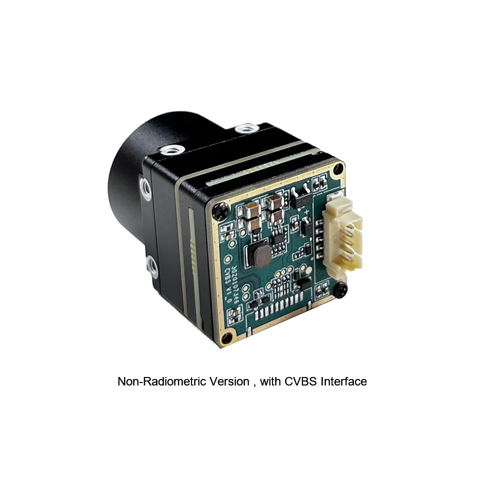
Uncooled Mini 384×288 Thermal Camera Module For Drones
The MINI series infrared thermal imaging temperature measurement module is a compact, high-precision instrument built for inline temperature monitoring. Utilizing a field-proven uncooled VOx sensor with a 12 μm pixel pitch and 384×288 resolution, it combines rock-solid thermal stability with rich radiometric data feeds. Offering broad interface compatibility, it slots right into drone gimbals, robotic systems, factory automation stations, and structural health monitoring setups.
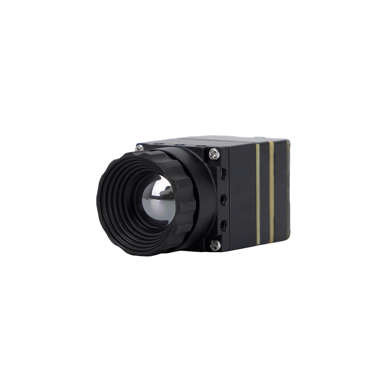
MD Series 384×288 Uncooled Infrared Thermal Camera Module
Purpleriver’s MD Series thermal camera core delivers industrial-grade precision for factory automation, security systems, and UAV gimbals. Built on a 12 μm uncooled VOx sensor, it outputs high thermal sensitivity (NETD ≤ 40 mK) for crisp edge clarity. Its compact footprint, true plug-and-play architecture, and multi-protocol interface (MIPI/USB/CVBS) make it an easy drop-in for diverse embedded carriers. Engineered by a technical team with Hong Kong University of Science and Technology roots and former Huawei HiSilicon hardware backgrounds, the MD Series offers deep OEM/ODM customization for demanding commercial runs, available through KUYANG or direct production channels.
6. Custom OEM/ODM Engineering Lifecycle & Firmware Tuning
Standard off-the-shelf camera blocks rarely fit seamlessly when you're dealing with tight robotic enclosures, custom 3-axis gimbals, or custom carrier boards. A full-stack OEM/ODM development process tailors the thermal sensor hardware directly to your mechanical, electrical, and optical constraints.
Custom PCB Layout & Physical Interface Engineering
Rigid, boxy boards create packaging bottlenecks inside aerodynamic drone fairings or handheld inspection tools. Custom board spins solve this cleanly:
- ✅ Split Flex-Rigid Form Factors: Separating the sensitive microbolometer sensor head from the main ISP and interface board via a flexible ribbon cable lets you mount the optics directly inside a tiny micro-gimbal while keeping the heavier processing hardware in the main drone fuselage.
- ✅ Locking Micro-Coaxial Connectors: Swapping standard USB headers for board-to-board locking micro-coaxial connectors (like Hirose DF40, DF36, or IPEX Cabline series) stops vibration disconnects dead in their tracks during heavy flight turbulence or machine cycling.
Athermalized Optical System Design
Infrared glass materials, especially Germanium, undergo significant thermal drift in their refractive index ($\frac{dn}{dt} \approx 396 \times 10^{-6}/\text{K}$ for Ge). Left uncorrected, temperature shifts throw the lens completely out of focus. Industrial optical setups counter this with two key approaches:
- ⚙️ Germanium Optics: Germanium gives you a massive refractive index ($n \approx 4.0$) and minimal chromatic dispersion, making it ideal for large-aperture, high-resolution optical paths.
- ✅ Chalcogenide Glass & Optical Athermalization: Combining Germanium and Chalcogenide elements inside an engineered mechanical barrel mechanically cancels out thermal expansion, keeping your focus locked tight across the entire operating range ($-40^\circ\text{C}$ to $+80^\circ\text{C}$) without needing noisy, power-hungry motorized focus drives.
Low-Level SDKs, Embedded Linux Drivers & ROS Ecosystem Integration
Edge AI platforms need low-overhead, direct access to raw thermal matrices. Production-grade OEM cores back this up with full Linux driver stacks:
- ⚙️ V4L2 & GStreamer Integration: Hardware-accelerated GStreamer pipelines capture 14-bit radiometric RAW streams or 8-bit visual feeds directly into OpenCV, TensorRT, or ONNX Runtime pipelines with zero-copy memory transfers.
- ⚙️ Native ROS & ROS2 Drivers: Dedicated ROS nodes publish standard
sensor_msgs/Imageandsensor_msgs/CameraInfotopics with hardware timestamps, dropping right into robotic SLAM and autonomous navigation stacks. - ✅ Custom On-Die Logic: Custom FPGA/DSP firmware modifications allow you to run Region-of-Interest (ROI) temperature calculations, high-temperature alarm thresholds, and dynamic hot-spot tracking right on the core before frames ever touch the serial bus.

7. Deep-Dive Industrial Engineering FAQ
How do we ensure embedded Linux and ROS compatibility when integrating an OEM thermal camera module?
sensor_msgs/Image topics. This setup lets you feed raw temperature matrices straight into TensorRT or OpenCV pipelines without messing with custom frame decoders.
Can Purpleriver customize thermal camera module hardware for SWaP-constrained drone payloads?
What is the technical difference between 14-bit RAW radiometric output and 8-bit YUV thermal output?
Why is 12μm pixel pitch microbolometer technology advantageous for aerial gimbal integration?
📚 References & Further Reading
- Industry Standard: Embedded Linux Prototyping on Single-Board Architectures via Raspberry Pi
- Verified Sourcing: Purpleriver Industrial Thermal Sensors & OEM Production on KUYANG
- Related Technical Guide: MD Series 384×288 Thermal Imaging Specification & Low-Power Integration Analysis
- Payload Architecture: MIPI Thermal Camera Modules for Drone System Architecture
- Hardware Upgrade: Modernizing to Mini2 Compact LWIR 640×512 Cores for Mobile Robotics





