









Best 25Hz Thermal Camera Module Guide: High-Frame-Rate Cores for Drones & Edge AI
2026年8月31日
OEM Thermal Camera Module Selection & Integration Guide: Custom IR Cores for Drones & Machine Vision
2026年9月2日
Lightweight Thermal Camera Solutions: Compact LWIR Modules for Drones & Edge AI
If you have ever tried cramming an uncooled thermal core into a sub-250g drone or a tight robotic gimbal, you know the harsh reality: physics does not cut you any slack. Whether you are building aerial inspection rigs, tactical micro-drones, autonomous mobile robots (AMRs), or battery-strapped IoT sentries, thermal imaging hardware lives under brutal physical constraints. You need crisp, long-wave infrared (LWIR) visibility to cut through total darkness, smoke, and industrial haze, but you cannot afford the heavy glass, clunky heat sinks, or battery-draining processing boards that older systems required.
Here's the deal: cutting weight in thermal imaging is not as simple as shaving a few millimeters off an aluminum enclosure. In our line of work, every single gram you add to a camera payload triggers a painful ripple effect across the entire system. It demands beefier gimbal motors, forces you to hang heavier counterweights, pulls more continuous current from your power distribution board, and chops precious minutes off flight endurance. When an airframe has to stay under tight regulatory weight thresholds, traditional thermal packages are a dead end.
Building a top-tier lightweight thermal camera payload means walking a tightrope between Size, Weight, Power, and Cost (SWaP-C) without letting your optical and radiometric performance fall apart. We are talking about pulling down sub-40mK Noise Equivalent Temperature Difference (NETD) sensitivity, maintaining steady 50Hz frame rates, and handling native resolutions from standard 640×512 VGA up to 1280×1024 high-definition—all while holding the core sensor package down to 30 to 60 grams. Thanks to modern Application-Specific Integrated Circuits (ASICs) replacing power-hungry Field-Programmable Gate Arrays (FPGAs) and wafer-level packaging (WLP) overhauling microbolometer focal plane arrays, the playing field has completely changed.
In this engineering breakdown, we will walk through the core physics, optical design choices, silicon architectures, and mechanical mounting tactics that make ultra-compact uncooled LWIR cameras tick. We will also dig into how hardware-level video encoding and versatile interfaces—from bare-metal MIPI-CSI-2 to zero-latency analog CVBS and network RTSP—let you feed high-speed edge AI models and real-time radiometric telemetry straight to onboard processors without frying your thermal or power budgets.
Mini 640×512 Thermal Imaging Core Demo Video
Table of Contents
- 👉 1. The SWaP-C Imperative: Engineering Lightweight Thermal Cameras
- 👉 2. ASIC vs. FPGA Core Architectures in Micro Thermal Imaging
- 👉 3. Industrial Drone, Gimbal & Robotic Integration Strategies
- 👉 4. Edge AI Computer Vision & Radiative Temperature Pipelines
- 👉 5. High-Performance Lightweight Thermal Camera Product Showcase
- 👉 6. Hardware Interfacing & Streaming Protocols (MIPI, RTSP, CVBS, USB)
- 👉 7. Comprehensive Technical FAQ & Engineering Solutions
1. The SWaP-C Imperative: Engineering Lightweight Thermal Cameras
When you start stripping down an uncooled LWIR sensor core to hit aggressive weight targets, you run headfirst into optical physics and thermal dynamics. Out on the flight line or inside a dynamic robotic cell, mass is not an isolated metric. If your camera payload creeps up, your rotational inertia climbs exponentially ($I = m \cdot r^2$). That forces your gimbal stabilization loops to work harder, dumping heat right back into your sensor enclosure and draining your flight battery prematurely. Nailing your SWaP-C targets without degrading optical throughput or signal fidelity is where true engineering begins.
Let's look at the optical train. Operating in the 8μm to 14μm spectral window means standard optical glass is completely opaque. Traditionally, optical designers turned straight to monocrystalline Germanium (Ge). It is a fantastic material optically—its high refractive index (~4.0) keeps lens curvatures shallow and keeps chromatic aberration in check. The catch? Germanium is heavy, sitting at a dense 5.32 g/cm³. If you mount a fast Germanium multi-element lens on a micro core, that front-heavy glass assembly instantly becomes your payload's biggest weight liability.
To break through this barrier, modern lightweight optical assemblies rely heavily on specialized Chalcogenide glass compounds (such as Ge-Sb-Se or As-Se-Te formulations) turned on single-point diamond machines with hybrid diffractive surfaces. Chalcogenide materials drop the density down to roughly 4.4 to 4.7 g/cm³, shedding vital grams right off the nose of the payload. More importantly, Chalcogenide features a significantly lower thermal coefficient of refractive index (dn/dT) than pure Germanium. That is the secret to building passively athermalized lens assemblies. By carefully pairing Chalcogenide optics with balanced aluminum and Invar or polyoxymethylene barrel spacers, the mechanical expansion of the housing cancels out the thermal shift of the glass across -40°C to +85°C. You get crisp focus across harsh operating environments without the dead weight, complexity, or power draw of motorized focus mechanisms.
On the sensor side, the steady shift in microbolometer Focal Plane Array (FPA) fabrication from older 17μm pixel nodes down to modern 12μm (and emerging sub-10μm) processes has been a massive leap forward. A 12μm 640×512 array takes up nearly half the physical die footprint of its 17μm predecessor. Because that image circle is much smaller, optical designers can hit identical Fields of View (FOV) and target Ground Sampling Distances (GSD) using shorter focal lengths and significantly smaller front objective diameters. That optical scaling trick slashes the volume and mass of your infrared glass, making sub-40g fully enclosed, flight-ready thermal imaging packages an everyday reality.
If you want a deeper look at real-world deployment parameters for airborne platforms, check out our dedicated field breakdown on choosing a high-performance thermal micro camera module for drones and embedded AI.
2. ASIC vs. FPGA Core Architectures in Micro Thermal Imaging
The processing brain inside your camera module makes or breaks your thermal budget, power consumption, and mechanical enclosure design. Uncooled microbolometers do not output clean, ready-to-view pictures out of the box. They output raw, minute micro-volt resistance shifts across hundreds of thousands of micro-machined Vanadium Oxide (VOx) or Amorphous Silicon (α-Si) bridge structures. Translating those microscopic resistance fluctuations into a low-noise, radiometric video stream takes substantial real-time processing horsepower.
Historically, manufacturers tackled this digital signal crunching by dropping an FPGA onto the processing stack. FPGAs are great for rapid prototyping and firmware updates, but out in the field, they are brutal on your SWaP budget. A typical FPGA-based thermal video pipeline easily pulls between 2.5W and 6.0W of continuous power. In a compact, sealed enclosure, that electrical power converts straight into heat. Because microbolometers are designed to detect microscopic shifts in thermal radiation, that internal heat buildup warms up the camera chassis, introducing nasty fixed-pattern noise (FPN) and causing radiometric calibration drift. To survive, FPGA cores need heavy aluminum heat sinks and copper heat pipes—which completely ruins your weight budget.
Transitioning to dedicated Application-Specific Integrated Circuits (ASICs) solves this problem at the silicon level. By baking the control logic, low-noise analog-to-digital converters (ADCs), and non-uniformity correction pipelines directly into dedicated silicon, modern ASIC cores drop continuous power dissipation down to a lean 0.8W to 1.2W at full 50Hz operation. In the shop, this changes everything: internal thermal blooming is virtually eliminated, and you can mount the module inside a tiny, completely sealed carbon-fiber or polymer chassis without needing auxiliary heat spreaders or active airflow.
An advanced ASIC hardware pipeline runs several critical digital corrections simultaneously at full line-rate speeds:
- ⚙️ Multi-Point Non-Uniformity Correction (NUC): Normalizes microscopic pixel-to-pixel responsivity variations inherent to semiconductor manufacturing tolerances across variable operational temperatures.
- ⚙️ Dynamic Bad Pixel Replacement (BPR): Identifies dead, flashing, or drifting pixels on the fly and interpolates clean data from neighboring elements to eliminate spatial dropouts in high-contrast scenes.
- ⚙️ Digital Detail Enhancement (DDE) & Adaptive DRC: Compresses high-dynamic-range 14-bit or 16-bit raw radiometric data down into clean 8-bit display spaces without washing out structural contours, vehicle silhouettes, or subtle thermal edges.
- ⚙️ Real-Time Shutterless Drift Tracking: Uses embedded thermistors across the focal plane and lens mount to dynamically adjust calibration curves, drastically cutting down the need for noisy mechanical shutter clicks that freeze your video feed during critical operations.
On top of running cooler, ASIC engines boot almost instantly. While an FPGA-based stack can take 8 to 15 seconds to parse its bitstream, settle power rails, and initialize its memory bus, an ASIC-powered micro module streams calibrated, stable thermal video in under 3.0 seconds from cold boot.
3. Industrial Drone, Gimbal & Robotic Integration Strategies
Getting a lightweight thermal camera mounted onto a micro-gimbal or robotic chassis requires balancing mechanical stability, vibration isolation, and clean electrical routing. Small aerial platforms—especially sub-250g micro-drones built under FAA Category 1 and EASA Open A1 guidelines—are unforgiving dynamic environments full of high-frequency motor harmonics, prop wash, and razor-thin Center-of-Gravity (CoG) margins.
When mounting an LWIR core into a 2-axis or 3-axis brushless micro-gimbal, keeping the rotational inertia down is priority number one. Long, front-heavy lens assemblies push the camera's center of mass away from the pitch and yaw pivot points. This forces your brushless gimbal motors to pull continuous corrective current just to keep the sensor level. That extra current heats up the gimbal motors, which then conducts parasitic heat right into your camera casing, setting off thermal drift across the microbolometer. Sticking with compact, short-barrel fixed-focus optics (like 9.1mm, 13mm, or 19mm athermalized lenses) keeps the CoG locked close to the motor shafts, preventing motor strain and eliminating high-speed stabilization chatter.
Mechanical vibration isolation is another area where builds often fail. Multirotor propulsion systems throw off continuous structural vibrations in the 100Hz to 400Hz band. If those vibrations transfer into your thermal sensor, they can trigger optical microphonics—a condition where the ultra-thin, suspended microbolometer membranes oscillate mechanically inside their vacuum cavities. This manifests as horizontal banding or rolling wave artifacts across your video. To stop this, always isolate the camera core using tuned silicone dampeners or viscoelastic mounts matched precisely to your airframe's dominant motor frequencies.
Electromagnetic Interference (EMI) is another major headache. Modern inspection drones pack dense switching regulators, high-amperage Electronic Speed Controllers (ESCs), and high-output RF transmitters (like 900MHz telemetry or 5.8GHz video links) into tight spaces. The analog front-end of a high-sensitivity LWIR sensor core operates on low-voltage signals where tiny microvolt changes translate into fractions of a degree Celsius. Unshielded wiring will easily pick up high-frequency RF noise, causing vertical banding and ruining your NETD. Always use shielded flexible flat cables (FFC) with grounded aluminum-mylar wraps, snap ferrite chokes onto DC input lines, and keep solid ground plane isolation between your power board and video breakout lines.
If you are working with distributed teams or managing international design documentation, referencing localized engineering standards such as the Russian thermal core integration breakdown (как выбрать лучший модуль тепловизио) or the Arabic industrial thermal camera deployment guide (دليل اختيار وحدة كاميرا التصوير الحرا) helps keep mechanical, optical, and regulatory specifications aligned across borders.
4. Edge AI Computer Vision & Radiative Temperature Pipelines
A lightweight thermal camera should not operate in a silo. To get real utility out of autonomous systems, the sensor must stream clean, high-bandwidth data directly into onboard Neural Processing Units (NPUs) and edge computers—like the NVIDIA Jetson Orin series, Rockchip RK3588, or Raspberry Pi CM4. Pairing lightweight thermal vision with edge compute gives you true autonomous tracking, robotic navigation, and automated industrial diagnostics without depending on spotty cloud links or high-latency ground stations.
Unlike visible-light RGB sensors that simply deliver color frames, thermal cores operate in two fundamentally different data modes. Understanding how these pipelines work determines how you structure your edge software stack:
1. 8-Bit Display Stream for Autonomous Computer Vision: In this pipeline, the camera's internal ASIC handles the heavy lifting: multi-point NUC, dynamic contrast enhancement, and color mapping (White-Hot, Black-Hot, Ironbow). It outputs standard 8-bit YUV, RGB, or H.264/H.265 video. Lightweight convolutional neural networks (like YOLOv8, YOLOv10, or MobileNet) can ingest these frames immediately for real-time bounding-box detection, perimeter security, and path planning. Because LWIR signatures do not care about shadows, headlights, or complete darkness, vision models maintain reliable detection metrics even when visible-light sensors are completely blinded by fog or smoke.
2. 14-Bit / 16-Bit Radiometric Telemetry for Quantitative Analytics: For utility inspections—like scanning photovoltaic arrays for hot spots, spotting overheated substation disconnects, or monitoring forest fire perimeters—an 8-bit visual stream is not enough. You need the raw mathematical numbers. The camera transmits a full 14-bit or 16-bit array over a low-overhead bus like MIPI-CSI-2 or high-speed USB. Each raw pixel value correlates directly to an apparent radiative temperature based on the Stefan-Boltzmann law, compensated for target emissivity ($\varepsilon$), ambient reflected energy, path transmission, and distance.
In the field, developers configure pipelines using OpenCV, GStreamer, and TensorRT to run both tasks in parallel. The edge processor ingests the raw 14-bit radiometric matrix, isolates temperature spikes using threshold segmentation, and runs an object-detection model on the compressed visual stream. If a bearing or solar cell exceeds safe operating limits, the system tags the anomaly, writes georeferenced radiometric metadata to flash storage, and commands the gimbal to hold target lock automatically.
5. High-Performance Lightweight Thermal Camera Product Showcase
Matching the right LWIR core to your project means balancing spatial resolution, optical parameters, power draw, and physical dimensions. Below are two proven, industrial-grade OEM uncooled thermal camera modules engineered by KUYANG, delivering high SWaP-C efficiency for aerial robotics, handheld instruments, and embedded edge vision platforms.
1. High Resolution Uncooled Infrared 1280×1024 Thermal Imaging LWIR Camera
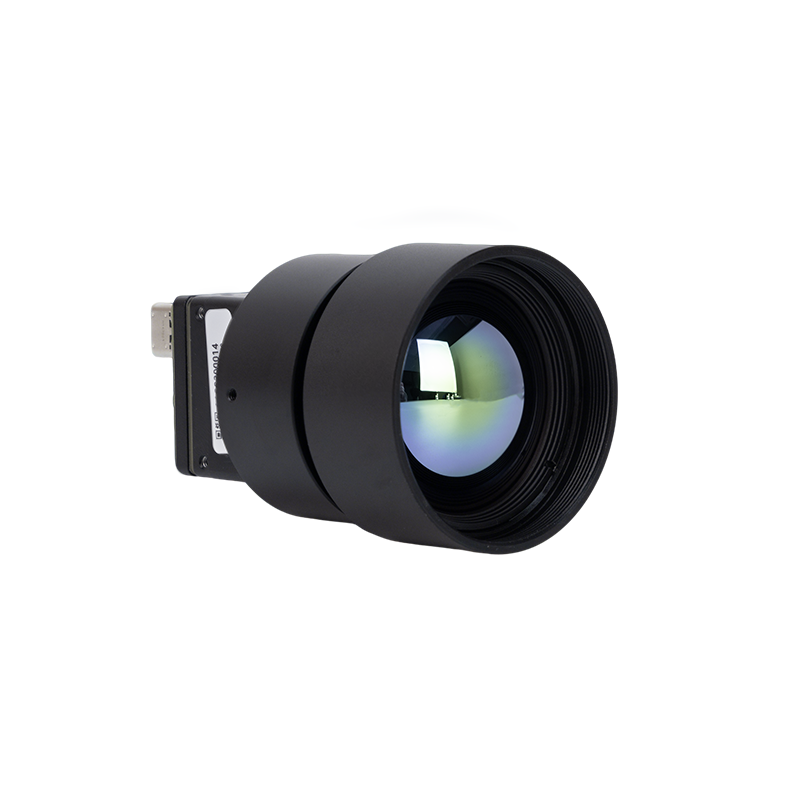
Built for long-range tactical surveillance, high-altitude mapping, and industrial perimeter defense, this ultra-high-resolution thermal camera module pairs a 1280×1024 microbolometer array with high-efficiency optics. Built on a 12μm pixel pitch with thermal sensitivity (NETD) under 40mK, it resolves minute temperature gradients and fine structural details over long stand-off distances. With onboard Non-Uniformity Correction, dynamic range enhancement, and multi-protocol serial control, it delivers high-fidelity radiometric performance in an impressively compact footprint.
- ✅ Array Resolution: 1280 × 1024 Native HD
- ✅ Pixel Pitch: 12μm Uncooled VOx/a-Si Focal Plane Array
- ✅ Spectral Band: 8 to 14μm (LWIR)
- ✅ Optical Configuration: 25mm high-transmission athermalized Germanium lens
- ✅ Thermal Sensitivity: NETD < 40mK (@ 25°C, F1.0)
- ✅ Frame Rate: 50Hz Real-Time Continuous Streaming
- ✅ Ideal Deployments: Tactical reconnaissance UAVs, perimeter security payloads, mapping platforms
2. Uncooled Infrared RJ45 CVBS RTSP IP 640×512 ASIC Thermal Sensor Camera Module

Engineered specifically for micro-UAVs, FPV tactical airframes, sub-250g robotic gimbals, and embedded AI nodes, this mini 640×512 module runs on a low-power ASIC core. It integrates direct hardware H.264/H.265 encoding over RJ45 Ethernet (RTSP/IP protocols) along with a concurrent zero-latency analog CVBS output. Drawing under 1W in steady state, this module runs cool without bulky heatsinks, making it an easy drop-in for tightly packed airframes.
- ✅ Array Resolution: 640 × 512 VGA
- ✅ Processing Core: Dedicated Low-Power ASIC Video & Radiometry Engine
- ✅ Pixel Pitch: 12μm Wafer-Level Packaging (WLP)
- ✅ Thermal Sensitivity: NETD < 35–40mK
- ✅ Dual Video Output: Direct RJ45 Ethernet (RTSP / ONVIF) + Analog CVBS simultaneously
- ✅ Power Profile: Optimized sub-1W core dissipation
- ✅ Ideal Deployments: Sub-250g inspection drones, FPV airframes, compact robotics, IoT nodes
6. Hardware Interfacing & Streaming Protocols (MIPI, RTSP, CVBS, USB)
Choosing the right physical bus and video transport protocol is where your hardware integration succeeds or fails. You have to match the data throughput, processing overhead, and latency constraints of your host system with the camera module's physical outputs.
| Interface Type | Data Format | Typical Latency | Host Processing Overhead | Ideal Use-Case |
|---|---|---|---|---|
| MIPI-CSI-2 | Raw 14-bit / 16-bit or YUV422 | < 10ms | Very Low (Direct DMA into SoC ISP) | Embedded AI, autonomous navigation, fast edge NPU inference |
| CVBS (Analog) | NTSC / PAL Composite Video | < 1ms (Near-Zero) | Zero (Direct connection to Analog VTX) | Tactical FPV piloting, micro UAV pilot feeds, direct monitor display |
| RJ45 Ethernet (RTSP/IP) | H.264 / H.265 Encoded Stream | 80ms – 180ms | Low (Hardware decode on client VMS) | Network IP security, enterprise UAV payloads, multi-sensor network hubs |
| USB 3.0 / USB-C (UVC) | UVC Video + Virtual COM Radiometry | 25ms – 45ms | Moderate (USB Host stack handling) | Plug-and-play PC diagnostics, handheld tools, robotic companion boards |
Practical Interface Design Guidelines:
- ⚙️ MIPI-CSI-2 Integration Rules: If you are pairing a thermal core directly with an NVIDIA Jetson or NXP i.MX8 board, MIPI-CSI-2 is the gold standard. It shoots pixel data over differential clock and data lanes straight into host memory via DMA, cutting latency below 10ms with almost no CPU load. Keep in mind: MIPI traces hate long runs. Keep your PCB traces under 100mm to 150mm. If your camera sits out on a gimbal arm away from the compute board, use automotive-grade SerDes bridges (like FPD-Link III or GMSL2) over micro-coaxial lines to avoid signal degradation.
- ⚙️ Analog CVBS Wiring: When low latency is your absolute top priority—like manual FPV piloting through tree canopies or confined industrial indoor spaces—analog CVBS is tough to beat. It bypasses compression blocks and frame buffers, giving you true sub-millisecond transmission straight to an analog 5.8GHz video transmitter (VTX). Keep your video ground line tightly paired with the signal pin to eliminate ground loop hum caused by ESC switching noise.
- ⚙️ Ethernet RTSP/IP Architecture: If your module features onboard H.264/H.265 compression, you can bypass local host encoding completely. The camera streams an ONVIF Profile S or RTSP feed directly across your digital data links (like Doodle Labs, Microhard, or standard Wi-Fi bridges). This keeps your software architecture clean, letting multiple base stations or video management servers pull the stream simultaneously without bogging down your onboard flight controller.
7. Comprehensive Technical FAQ & Engineering Solutions
How do I optimize a lightweight thermal camera payload for sub-250g drones without sacrificing image sensitivity?
Start by selecting a modern ASIC-based core with a 12μm pixel pitch microbolometer in a Wafer-Level Package (WLP). WLP strips out bulky ceramic carriers, dramatically shrinking both footprint and mass. Match the sensor with a short focal length (e.g., 9.1mm or 13mm) fast-aperture (f/1.0 to f/1.1) athermalized Chalcogenide lens rather than dense Germanium optics. Power the module from a clean 3.7V–5V step-down regulator; ASIC modules pulling under 1W generate minimal internal heat, letting you ditch heavy auxiliary heat sinks. Finally, route video via analog CVBS straight to a micro-VTX or via MIPI into a single-board computer using ultra-flexible flat cables (FFC) to prevent adding mechanical resistance to your gimbal motors.
What is the primary difference between consumer thermal dongles and industrial OEM lightweight thermal modules?
Industrial OEM lightweight modules are built from the ground up for continuous 24/7 operation across wide operating ranges (-40°C to +85°C). They feature hardware-driven 50Hz video streaming, dedicated onboard Non-Uniformity Correction (NUC), sub-40mK NETD sensitivity, calibrated per-pixel radiometric telemetry, and low-latency physical buses (MIPI-CSI-2, RJ45 Ethernet, CVBS). Industrial cores also use shutter-based or dynamic shutterless calibration routines designed to avoid unexpected frame freezes during flight, paired with rugged surface-mount designs that easily handle motor vibration.
Why is a 50Hz frame rate critical for airborne thermal camera payloads compared to 9Hz sensors?
A 50Hz thermal engine refreshes spatial data every 20 milliseconds, delivering smooth, stable video during high-speed low-altitude passes. For autonomous tracking pipelines running YOLO or DeepSORT on edge NPUs, 50Hz data delivers the temporal resolution necessary to track moving vehicles, personnel, or livestock smoothly. For manual FPV operations, high frame rates dramatically reduce operator eye fatigue and provide the reaction time needed to dodge thin tree branches and power lines.
How do ambient operating temperature fluctuations cause thermal drift, and how is it corrected?
Industrial cores tackle drift through a mix of hardware and software corrections. A mechanical solenoid periodically drops a uniform temperature shutter in front of the sensor for roughly 200–400ms to recalibrate baseline pixel values. High-end ASIC cores also feature shutterless drift compensation: onboard thermistors track real-time temperature shifts across the lens barrel and sensor die, referencing multi-point factory calibration lookup tables (LUTs) to mathematically correct drift on the fly without freezing the live video stream during flight.
📚 References & Further Reading
- Industry Standard: Explore uncooled infrared sensor physics and microbolometer fundamentals via Wikipedia Microbolometer.
- Manufacturing Partner: Review professional OEM manufacturing capabilities and core component catalogs at KUYANG.
- Related Technical Guide: Discover architectural optimization strategies for aerial robotics in our guide on the High-Performance Thermal Micro Camera Module for Drones & Embedded AI.
- Russian Integration Guide: Access complete localized engineering frameworks for thermal core selection at как выбрать лучший модуль тепловизио.
- Arabic Engineering Framework: Review regional specifications and OEM integration protocols at دليل اختيار وحدة كاميرا التصوير الحرا.





