MIPI Thermal Camera Module: High-Res Embedded LWIR Cores for Drones & Edge AI
2026年10月14日
Thermal Imaging Camera Guide: Real-World Testing, Resolution & OEM Cores
2026年10月15日

Thermal Camera Guide: How It Works, Value Analysis, and OEM Module Integration
Thermal imaging has transitioned from specialized military hardware into an essential pillar of industrial automation, predictive maintenance, security surveillance, and uncrewed aerial vehicle (UAV) payload engineering. Despite this widespread adoption, engineering and procurement teams frequently encounter a persistent challenge: distinguishing between low-cost consumer thermal gadgets and ruggedized, radiometric OEM cores capable of mission-critical accuracy. Selecting the wrong sensor architecture leads to thermal drift, inaccurate temperature telemetry, severe latency bottlenecks, and integration failures under extreme operational environments.
Deploying an industrial-grade thermal camera requires a precise understanding of infrared physics, microbolometer material behaviors, optical transmission limitations, and embedded interface protocols. Whether you are engineering a multi-axis stabilized gimbal for airborne infrastructure inspection or designing an autonomous factory machine vision array, your system depends on real-time radiometric precision, low Noise Equivalent Temperature Difference (NETD), and predictable Size, Weight, and Power (SWaP) characteristics. This comprehensive guide breaks down the operational physics of Long-Wave Infrared (LWIR) sensing, evaluates the cost-versus-value dynamics of modern detector architectures, and provides a clear integration roadmap for embedded developers and hardware architects.
Table of Contents
- 👉 1. How Thermal Cameras Work: The Physics of Infrared Detection
- 👉 2. Core Technical Metrics: Deconstructing Resolution, NETD, and Frame Rates
- 👉 3. Value Analysis: Consumer Diagnostic Gadgets vs. Industrial Radiometric Cores
- 👉 4. OEM Integration Architecture: Interfacing with Single-Board Computers and Industrial Frameworks
- 👉 5. SWaP-C Optimization for Airborne Payloads and Mobile Robotics
- 👉 6. Comprehensive Product Showcase: Industrial Thermal Camera Modules
- 👉 7. Deep-Dive Technical FAQ
1. How Thermal Cameras Work: The Physics of Infrared Detection
A thermal camera operates on fundamental thermodynamic principles, detecting radiation within the electromagnetic spectrum that is completely imperceptible to the human visual apparatus. While visible-light cameras rely entirely on photons reflected off structural surfaces within the narrow 0.38 to 0.75-micrometer (µm) band, infrared systems detect natively emitted radiation generated by molecular kinetic agitation. Every object whose thermal state sits above absolute zero (0 Kelvin or -273.15°C) emits electromagnetic energy characterized by internal vibrational and rotational atomic transitions.
The quantification of this thermodynamic reality originates in Planck’s Radiation Law, which formulates the spectral radiance of electromagnetic energy emitted by an ideal blackbody at absolute temperature equilibrium:
B(λ, T) = (2 * h * c²) / (λ&sup5; * (exp((h * c) / (λ * k_B * T)) - 1))
In this physical construct, h represents the Planck constant (6.626 x 10⁻³⁴ J·s), c defines the speed of light in vacuum (2.998 x 10⁸ m/s), λ denotes emission wavelength, k_B constitutes the Boltzmann constant (1.381 x 10⁻²³ J/K), and T designates the absolute thermodynamic temperature of the radiating mass in Kelvin. Integrating Planck’s function across the entire continuous electromagnetic spectrum yields the comprehensive Stefan-Boltzmann Law, establishing that the total radiant exitance from a blackbody surface scales directly with the fourth power of its thermodynamic temperature:
j* = ε * σ * T⁴
Here, ε signifies surface emissivity (a coefficient varying between 0.00 for an ideal specular reflector and 1.00 for an optimal blackbody emitter), while σ represents the universal Stefan-Boltzmann constant (5.670 x 10⁻⁸ W/m²·K⁴). When examining target profiles across ambient terrestrial environments (spanning -40°C up to +150°C), Wien’s Displacement Law determines that the apex of spectral radiant exitance gravitates decisively toward the Long-Wave Infrared (LWIR) atmospheric transmission spectrum, located primarily between 8.0 and 14.0 µm.
Terrestrial ambient environments present a severe challenge to infrared propagation because atmospheric moisture, carbon dioxide molecules, and particulate aerosols absorb electromagnetic waves across vast swaths of the spectrum. Fortunately, the 8.0 to 14.0 µm spectrum coincides with an exceptionally clear atmospheric window where transmission losses drop to practical operational minimums. This optical transmission window allows LWIR uncooled thermal imagers to capture radiometric signatures over long outdoor sightlines, through adverse weather conditions, and across dust-laden manufacturing floors without encountering prohibitive signal attenuation.
At the center of every modern uncooled thermal camera resides the focal plane array (FPA) microbolometer. Unlike high-end military cryogenically cooled sensors that utilize narrow bandgap semiconductor photon detectors (such as Mercury Cadmium Telluride or Indium Antimonide requiring bulky, energy-draining Stirling mechanical coolers to sustain 77 Kelvin), uncooled microbolometers operate stably at normal ambient system temperatures. The focal plane array consists of a microscopic, two-dimensional matrix of pixel structures micromachined via microelectromechanical systems (MEMS) processes atop a complementary metal-oxide-semiconductor (CMOS) Readout Integrated Circuit (ROIC).
Each discrete microbolometer pixel consists of an absorptive thin-film membrane suspended above the underlying silicon substrate by delicate, micro-machined bridge isolation legs. These legs provide both structural support and an intentional, high-resistance thermal path that restricts heat dissipation into the surrounding bulk substrate. Incoming LWIR photons pass through specialized infrared optics, striking the suspended membrane and transferring energy that increases its temperature by minute fractions of a millikelvin.
The suspended membrane contains an active thermistor material exhibiting an exceptionally pronounced Temperature Coefficient of Resistance (TCR). The industrial market relies predominantly on two primary chemical thin films: Vanadium Oxide (VOx) and Amorphous Silicon (α-Si). While Amorphous Silicon provides cost-efficient semiconductor manufacturing scalability, Vanadium Oxide stands as the premier industrial and military benchmark. VOx thin films deliver a substantially superior TCR (consistently demonstrating resistance shifts of -2% to -3% per Kelvin of temperature delta) alongside a drastically suppressed 1/f electrical flicker noise profile. As thermal radiation modulates the physical resistance of the VOx film, the ROIC applies a minute electrical bias, converts these resistance differentials into high-speed analog voltages, and presents digitized thermal raw streams to an onboard processing ASIC or FPGA.
Because typical optical-grade silicates, standard soda-lime float glass, and common acrylic polymers exhibit near-total opacity across wavelengths past 2.5 µm, standard camera lenses cannot be used for thermal imaging. Uncooled LWIR systems demand specialized optical elements manufactured from materials that remain transparent within the 8 to 14 µm waveband. Monocrystalline Germanium (Ge), synthetic Chalcogenide glass compounds, and Zinc Selenide (ZnSe) serve as the foundational optical media for thermal imaging. Precision optics manufacturers like LightPath Technologies employ advanced diamond-turning and precision glass-molding techniques to fabricate anti-reflective, aspheric chalcogenide elements that maximize photon throughput, minimize spherical aberrations, and maintain focus across extensive industrial operating temperatures.
2. Core Technical Metrics: Deconstructing Resolution, NETD, and Frame Rates
Procurement teams, automation engineers, and embedded systems developers must navigate beyond consumer-oriented marketing narratives to objectively evaluate thermal performance. The operational diagnostic utility of an industrial thermal core rests on four interdependent engineering parameters: spatial resolution, pixel pitch, thermal sensitivity (NETD), and temporal frame rate.
1. Spatial Matrix Resolution and Pixel Pitch: The spatial resolution denotes the physical quantity of independent microbolometer detector elements fabricated on the focal plane array. Standard industrial native resolutions include:
- ⚙️ 160 × 120 pixels (19,200 detector elements): Found in baseline thermal trigger switches, non-critical process checks, and compact safety proximity sensors.
- ⚙️ 256 × 192 pixels (49,152 detector elements): An entry-level format for small OEM machine diagnostics and handheld predictive maintenance devices. A comprehensive exploration of this balance between form factor and optical clarity can be found in our technical breakdown of thermal camera module 256x192 25mm solutions.
- ⚙️ 384 × 288 pixels (110,592 detector elements): The baseline standard for industrial condition monitoring, machine vision inspection, and stabilized UAV airborne payloads.
- ⚙️ 640 × 512 pixels (327,680 detector elements): The premier resolution class for radiometric enterprise asset evaluation, structural failure analysis, long-distance perimeter surveillance, and high-altitude airborne reconnaissance.
Concurrently, Pixel Pitch dictates the center-to-center distance separating adjacent microbolometer pixels, expressed in micrometers (µm). Over the past decade, the infrared industry has migrated away from legacy 25 µm and 17 µm architectures toward contemporary 12 µm fabrication techniques. Shrinking the pixel pitch to 12 µm dramatically reduces the physical silicon die area needed for a given resolution. This reduction directly translates into smaller, lighter, and more economical Germanium and Chalcogenide optical assemblies. The physical relationship governing optical magnification and target field resolution is expressed via the Instantaneous Field of View (IFOV):
IFOV = Pixel Pitch (d) / Focal Length (f)
A smaller pixel pitch yields a tighter IFOV for any designated lens focal length. This mathematical geometry allows payload engineers to reach higher spatial resolving power across distant targets without stacking oversized, high-mass lens barrels onto restricted payload bays.
2. Thermal Sensitivity: Noise Equivalent Temperature Difference (NETD): While spatial resolution dictates how sharp an image appears geometrically, NETD establishes the camera's ability to distinguish subtle thermal variations across a scene. Expressed in millikelvins (mK), NETD represents the equivalent temperature differential at the target plane that produces an electrical signal output equal to the intrinsic root-mean-square (RMS) noise floor of the detector system:
NETD = V_noise / (dV_signal / dT)
Lower NETD figures denote higher thermal sensitivity:
- ⚙️ Consumer Grade (≥ 60 mK to 100 mK): Adequate for identifying broad thermal anomalies—such as finding severe draft pathways in residential architecture or missing attic insulation—but inadequate for detailed engineering assessments.
- ⚙️ Industrial Standard (≤ 40 mK to 50 mK): The baseline for industrial predictive maintenance, factory automation, and mechanical diagnostic operations, providing clear separation of subtle thermal gradients under variable operating conditions.
- ⚙️ High-End Radiometric OEM (≤ 30 mK to 35 mK): Essential for complex condition-monitoring operations, resolving sub-trace electrical resistance anomalies on multilayer printed circuit boards, microscopic composite delaminations in aerospace structures, and low-contrast search-and-rescue scenes.
3. Temporal Resolution: Frame Refresh Rates: Thermal camera architectures fall into two primary operational refresh brackets dictated by both physical silicon design and international regulatory frameworks:
- ⚙️ Export-Restricted Refresh (≤ 9 Hz): Devices artificially capped below 9 frames per second are typically free from stringent international dual-use export controls (such as the US Export Administration Regulations - EAR). However, 9 Hz systems introduce severe motion blur, spatial tearing, and sensor lag, making them unviable for dynamic drone payloads, fast-moving mobile robotics, or automated industrial conveyor sorting lines.
- ⚙️ Full Dynamic Industrial Refresh (25 Hz / 30 Hz / 50 Hz): These full-motion systems provide continuous, low-latency video streaming critical for mobile platforms, stabilized gimbals, robotic navigation, and high-speed industrial safety systems.
4. Non-Uniformity Correction (NUC) and Thermal Drift Management: Because uncooled microbolometers measure tiny temperature differentials across a microscopic silicon array, individual pixels respond with slight variations in offset and gain characteristics. Furthermore, internal heat generated by adjacent ROIC electronics, video encoders, and ambient shifts causes thermal drift across the array. Without continuous compensation, the resulting video develops fixed-pattern noise (FPN), visual vignetting, and inaccurate radiometric readings.
Industrial thermal modules combat this drift using an integrated Mechanical Shutter NUC mechanism. Periodically, an internal solenoid drives a flat, thermally uniform shutter flag between the lens assembly and the focal plane array for a fraction of a second. The camera processor captures this uniform thermal baseline and recalculates the offset calibration matrix for every individual pixel, eliminating fixed-pattern noise. In defense and high-reliability aerospace systems where momentary video dropouts are unacceptable, advanced systems deploy Shutterless Algorithmic NUC, leveraging sophisticated predictive mathematical models to correct for drift in real time without mechanical interruption.
3. Value Analysis: Consumer Diagnostic Gadgets vs. Industrial Radiometric Cores
A frequent question asked by procurement managers, operations executives, and engineering team leads is straightforward: “Can our enterprise integrate sub-$400 consumer thermal dongles into our automated inspection or commercial drone payload workflows to reduce hardware capital expenditures?”
While consumer-grade smartphone thermal attachments serve basic consumer troubleshooting well, deploying them within enterprise, industrial, or airborne applications introduces severe functional limitations, reliability issues, and integration bottlenecks. Below is an engineering comparison illustrating the architectural divergence between consumer thermal gadgets and industrial OEM radiometric camera cores:
| Performance / Operational Metric | Consumer Diagnostic Gadgets ($200 - $400) | Industrial Radiometric OEM Modules |
|---|---|---|
| Native Thermal Resolution | 80 x 60 to 160 x 120 (heavily software-interpolated) | 384 x 288 up to 640 x 512 (true native uncooled VOx) |
| Thermal Sensitivity (NETD) | Poorer than ≥ 70 mK (frequently 100 mK - 150 mK) | Superior sensitivity (≤ 35 mK to 40 mK) |
| Temporal Refresh Rate | Hard limited to ≤ 8.7 Hz / 9 Hz (severe motion lag) | 25 Hz / 30 Hz / 50 Hz native dynamic streaming |
| Hardware Interface Protocols | Proprietary USB Type-C or Lightning connectors | CVBS Analog, RJ45 Ethernet, RTSP IP, Raw CMOS/MIPI |
| Output Data Stream | Lossy compressed video (MP4/H.264) or RGB images | 14-bit raw radiometric temperature arrays per pixel |
| Operational MTBF & Durability | Estimated 2,000 to 5,000 duty hours; plastic chassis | > 15,000 hours; ruggedized magnesium or aluminum alloy |
| Operating Temperature Range | 0°C to +35°C (drifts drastically outside baseline) | -40°C to +80°C (active internal drift compensation) |
| Software Integration Layer | Proprietary consumer mobile app (closed ecosystem) | Open C/C++ SDKs, Linux V4L2 drivers, ROS/ROS2, RTSP |
The total cost of ownership (TCO) calculation for consumer hardware frequently exposes an expensive false economy when applied to industrial operations:
- ⚙️ The Software Interpolation Trap: Low-cost commercial thermal attachments frequently claim display resolutions such as 640 x 480 or even 1080p. In reality, the underlying sensor is often an entry-level 80 x 60 microbolometer array paired with a cheap CMOS visible-light sensor. The host software blends visible edge contours over the low-resolution thermal image. While this edge-blending produces recognizable outlines on a smartphone screen, it fails entirely in quantitative machine vision workflows. For example, trying to detect thermal anomalies on individual 0402 surface-mount components on an industrial circuit board is impossible because the physical pixel pitch covers the entire board section, obscuring the true source of component overheating.
- ⚙️ Uncontrolled Radiometric Thermal Drift: Consumer thermal gadgets lack temperature-stabilized optical housings and internal thermal drift compensation models. If an inspection begins in an air-conditioned office and moves to a warm manufacturing floor or outdoor environment, the calculated surface temperature can drift by ±5°C to ±10°C. In predictive maintenance, such deviations can easily cause either false alarms or missed catastrophic failures in high-voltage switchgear, bearings, and distribution transformers.
- ⚙️ Closed Ecosystems and Driver Roadblocks: Consumer hardware relies on proprietary consumer mobile applications. These interfaces rarely provide open Linux APIs, hardware synchronization triggers, or programmatic access to uncompressed 14-bit raw radiometric data arrays. Industrial embedded systems requiring integration with autonomous navigation stacks, industrial programmable logic controllers (PLCs), or embedded edge-AI nodes cannot run reliably on closed consumer apps.
4. OEM Integration Architecture: Interfacing with Single-Board Computers and Industrial Frameworks
Integrating an industrial OEM thermal camera core into an automated platform or embedded computing system requires a clear understanding of the hardware, physical transport, and operating system driver layers. Unlike standard consumer USB webcams that stream compressed 8-bit YUV or MJPEG frames, an industrial thermal core must deliver rich radiometric streams containing precise per-pixel temperature values with minimal latency.
OEM thermal cores support several primary physical and protocol interfaces, each suited to specific system architectures:
- ✅ Analog Composite Video (CVBS): Transmits raw thermal imagery as an interlaced analog standard (NTSC or PAL). Because the signal is converted directly from the internal sensor without going through multi-frame compression buffers, CVBS delivers near-zero latency (under 10 milliseconds). This makes it an enduring favorite for direct analog FPV video transmitters on racing and utility inspection drones, as well as legacy monitor inputs across industrial security networks.
- ✅ Parallel Digital, MIPI-CSI-2, and USB: For embedded processing, high-speed digital buses connect the camera's internal Readout Integrated Circuit (ROIC) or ASIC directly to the host processor's memory architecture via Direct Memory Access (DMA). This transport delivers raw 14-bit digital temperature arrays directly to host RAM, allowing local algorithms to process pixel-level temperature data in real time.
- ✅ Ethernet RJ45 and RTSP Network Streaming: Designed for factory-wide networks and long-distance perimeter surveillance, modules with integrated network hardware compress thermal feeds into industry-standard H.264 or H.265 video streams. These streams are served over RTSP (Real-Time Streaming Protocol) alongside ONVIF-compliant management metadata, allowing immediate ingestion into Network Video Recorders (NVRs), enterprise SCADA platforms, or centralized security control centers.
Deploying thermal modules within embedded Linux architectures (such as Ubuntu, Debian, or embedded Yocto distributions) centers on the Video4Linux2 (V4L2) media framework. The kernel driver registers the thermal core as a standard media capture node (for example, /dev/video0). When handling raw radiometric feeds, the driver establishes high-bandwidth buffers using V4L2_PIX_FMT_Y16 (a 16-bit greyscale format where the 14 most significant bits carry raw radiometric sensor data) or custom metadata formats.
Developers implementing custom kernel-level communication and hardware bring-up pipelines can reference the comprehensive RS300 V4L2 driver setup and configuration guide, which details how kernel-space controls manage continuous thermal telemetry and device registers.
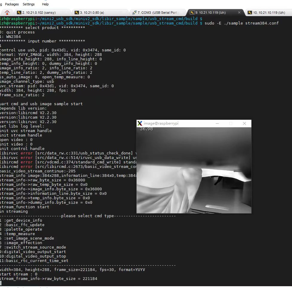
For edge-computing deployments, systems often interface directly with compact ARM-based single-board computers (SBCs). To implement high-framerate processing nodes on low-power platforms, follow our complete guide on configuring a high-resolution thermal imaging camera module for Raspberry Pi.
For auxiliary hardware control—such as commanding mechanical NUC shutter cycles, switching color palettes, configuring emissivity tables, or reading internal sensor temperatures—developers frequently incorporate dedicated microcontrollers. Microcontroller architectures, such as the open-source Arduino ecosystem, communicate with the thermal core over asynchronous UART serial interfaces or I2C command buses. This dedicated control layer offloads routine housekeeping tasks from the primary compute engine, improving reliability across critical operations.
Once raw 14-bit radiometric frames reach application memory, extracting absolute surface temperatures requires inverting the sensor's physical calibration curve. The conversion calculates true target surface temperature by accounting for ambient reflected radiation, optical attenuation, and target surface emissivity, translating raw pixel counts into calibrated degrees Celsius or Fahrenheit.
5. SWaP-C Optimization for Airborne Payloads and Mobile Robotics
Designing airborne sensor payloads for uncrewed aerial vehicles (UAVs) and autonomous mobile robots (AMRs) requires balancing four interrelated engineering constraints: Size, Weight, Power, and Cost (SWaP-C). On airborne platforms, every additional gram reduces flight time, increases motor draw, and shifts payload dynamics.
Weight and Gimbal Center of Mass Dynamics: Integrating a thermal camera into a 2-axis or 3-axis brushless gimbal requires keeping the payload envelope compact. Miniature OEM thermal modules address this challenge by stripping away heavy aluminum housings, utilizing lightweight magnesium-aluminum alloys, and adopting compact bare-board configurations that weigh under 50 grams. Minimizing the physical distance between the camera's center of mass and the gimbal's rotational axes reduces the inertia the brushless motors must stabilize, preventing motor saturation and unwanted oscillations during high-speed aerial flight.
Thermal Dissipation in Enclosed Payloads: A critical challenge in thermal camera engineering is detector self-heating. Because an uncooled microbolometer measures minute fractional-degree temperature differences, heat generated by nearby ROIC electronics, video processors, and motor drivers can radiate directly into the focal plane array if not properly managed. This parasitic heating introduces thermal gradients across the detector, causing severe radiometric measurement errors.
To prevent self-heating issues, high-efficiency OEM cores draw minimal electrical power—frequently under 1.0 to 1.5 Watts during continuous operation. In addition, effective gimbal designs implement isolated conduction paths, routing internal heat away from the optical barrel toward the outer structural housing. The aircraft's prop-wash airflow then serves as an active heatsink, keeping internal temperatures stable throughout the flight.
6. Comprehensive Product Showcase: Industrial Thermal Camera Modules
To meet the rigorous demands of airborne operations, robotics, and industrial monitoring, the following OEM thermal camera cores provide high-performance infrared imaging across compact, low-power form factors:
Uncooled Mini 384*288 Thermal Camera Module For Drones
The MINI series infrared thermal imaging temperature measurement module is a high-precision, small-sized, and universal online temperature measurement infrared thermal imager. It uses high-quality detectors, high resolution, stable performance, and powerful functions. It is equipped with multiple interfaces, making it a preferred product in application fields such as machine vision, safety inspection, intelligent manufacturing, equipment maintenance, robot drone airborne, and so on.
| Native Sensor Resolution | 384 × 288 Pixels |
|---|---|
| Detector Architecture | Uncooled Vanadium Oxide (VOx) Microbolometer |
| Operational Interfaces | Analog CVBS Output, Multi-pin Industrial Expansion Interface |
| Temperature Radiometry | High-Precision Online Radiometric Measurement |
| Design Optimization | Miniaturized Form Factor, Lightweight SWaP Optimization |
| Target Integration Fields | Drone Payloads, Machine Vision, Safety Inspection, Robotic Systems |
Engineering Analysis: The Mini 384×288 module delivers a well-engineered balance of resolution, thermal sensitivity, and compact design. Its integrated CVBS output provides an uncompressed analog feed with virtually zero transmission delay, making it an excellent choice for dynamic aerial navigation and direct FPV downlinks. The high-precision online temperature measurement engine processes radiometric telemetry directly on the module, offloading primary compute requirements from the host flight controller. This makes it a reliable, plug-and-play solution for aerial utility inspections, automated machine vision, and compact industrial robotics.
Uncooled Infrared RJ45 CVBS RTSP IP 640*512 Thermal Sensor Camera Module
Uncooled Infrared Mini 640*512 ASIC Thermal Imaging Camera Module For Drones. This advanced system incorporates an onboard ASIC processing pipeline that pairs high native resolution with flexible digital IP streaming options for enterprise applications.
| Native Sensor Resolution | 640 × 512 Pixels |
|---|---|
| Core Processor | Dedicated High-Performance Infrared ASIC |
| Networking & Connectivity | RJ45 Ethernet, Native RTSP IP Streaming, Direct CVBS Analog |
| Thermal Sensor Technology | Uncooled VOx Microbolometer Array |
| Key Operational Capabilities | Simultaneous Analog & IP Video Streaming, Radiometric Output |
| Target Integration Fields | Enterprise Drones, Remote Perimeter Defense, Factory SCADA Nodes |
Engineering Analysis: The 640×512 ASIC module is built for enterprise installations that require both high resolving power and network connectivity. Its 640×512 focal plane array provides nearly three times the active pixel density of 384-class sensors, providing the optical reach necessary for long-distance perimeter surveillance and high-altitude utility inspections. With native RJ45 network connectivity and hardware-level RTSP encoding, the onboard ASIC streams digital video directly to network recorders, security hubs, or edge AI nodes, while an independent CVBS output provides an uninterrupted analog feed for flight control or local diagnostic monitors.
7. Deep-Dive Technical FAQ
Are budget thermal cameras in the $200-$400 range actually worth owning for serious diagnostics?
How does a thermal camera measure surface temperature without physical contact?
Can I stream high-resolution thermal video directly to a Raspberry Pi or drone payload in real time?
📚 References & Further Reading
- Industry Standard: Precision Infrared Optical Design & Molded Chalcogenide Elements: LightPath Technologies
- Industry Standard: Embedded Computing & Microcontroller Logic Hardware Architecture: Arduino
- Related Guide: Embedded Linux Kernel Media Bring-up: Руководство по драйверу RS300 V4L2: Интеграция и конфигурация
- Related Guide: Edge Computing Implementation: High-Resolution Thermal Imaging Camera Module for Raspberry Pi Implementation Guide
- Related Guide: Compact Optical Form Factor Analysis: Thermal Camera Module 256x192 25mm: Engineering Performance and Tradeoffs