








640 512 35mm Thermal Camera Module: The Ultimate B2B Integration Guide for Drones and Edge AI
2026年7月3日
90mm Thermal Imaging Camera Module with Edge AI: Long-Range Precision
2026年7月6日
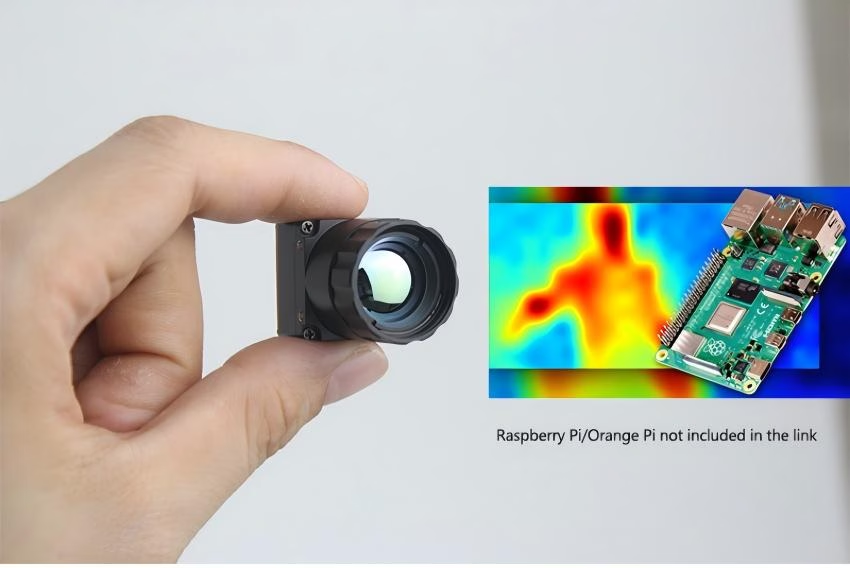
Best 256x192 25mm Thermal Camera Module for DIY Scopes & Drones: Cost-Effective Long-Range IR Sensor
For optical-system integrators, drone engineers, and custom thermal scope designers, selecting the ideal Long-Wave Infrared (LWIR) sensor core requires balancing spatial resolution, physical weight, power envelope, and optical reach. While 640x512 sensors remain the gold standard for wide-angle, high-end thermal platforms, a fast-emerging system architecture is taking over the mid-range industrial and tactical markets: pairing a cost-effective uncooled 256x192 resolution microbolometer with a narrow 25mm telephoto lens. This highly optimized configuration narrows the field of view (FoV) to concentrate spatial resolution over long distances, delivering outstanding detection ranges that rival much more expensive systems.
Designing an airborne drone payload or a lightweight DIY thermal scope demands components built to industrial standards, featuring low power consumption, minimal thermal drift, and robust electrical interfaces like MIPI CSI-2, USB, or CVBS. We will dissect the technical parameters that govern uncooled thermal camera modules, explore optical physics, analyze real-world integration architectures with Single Board Computers (SBCs), and showcase high-performance modules engineered to meet these exact hardware requirements.
Here’s the deal: if you want to build a system that actually performs in the field without breaking the bank, you have to understand exactly how your sensor pitch, lens dynamics, and carrier board talk to each other. In the shop, we don't rely on marketing fluff. We look at raw thermal sensitivity, hard DRI math, and clean board tracing. Let's get down to the brass tacks of how this configuration operates under real-world conditions.
Table of Contents
- 👉 1. The Physics of 256x192 Resolution & Microbolometer Pixel Pitch
- 👉 2. Why a 25mm Telephoto Lens Changes the Game: DRI Analysis
- 👉 3. Digital & Electrical Interfaces: MIPI CSI-2, USB, and CVBS Decoded
- 👉 4. Edge AI Integration & SDK Deployment on SBCs
- 👉 5. Curated B2B Product Catalog & Specs Showcase
- 👉 6. Implementation Blueprint: DIY Thermal Scope & Drone Payload
- 👉 7. Deep-Dive Technical FAQ
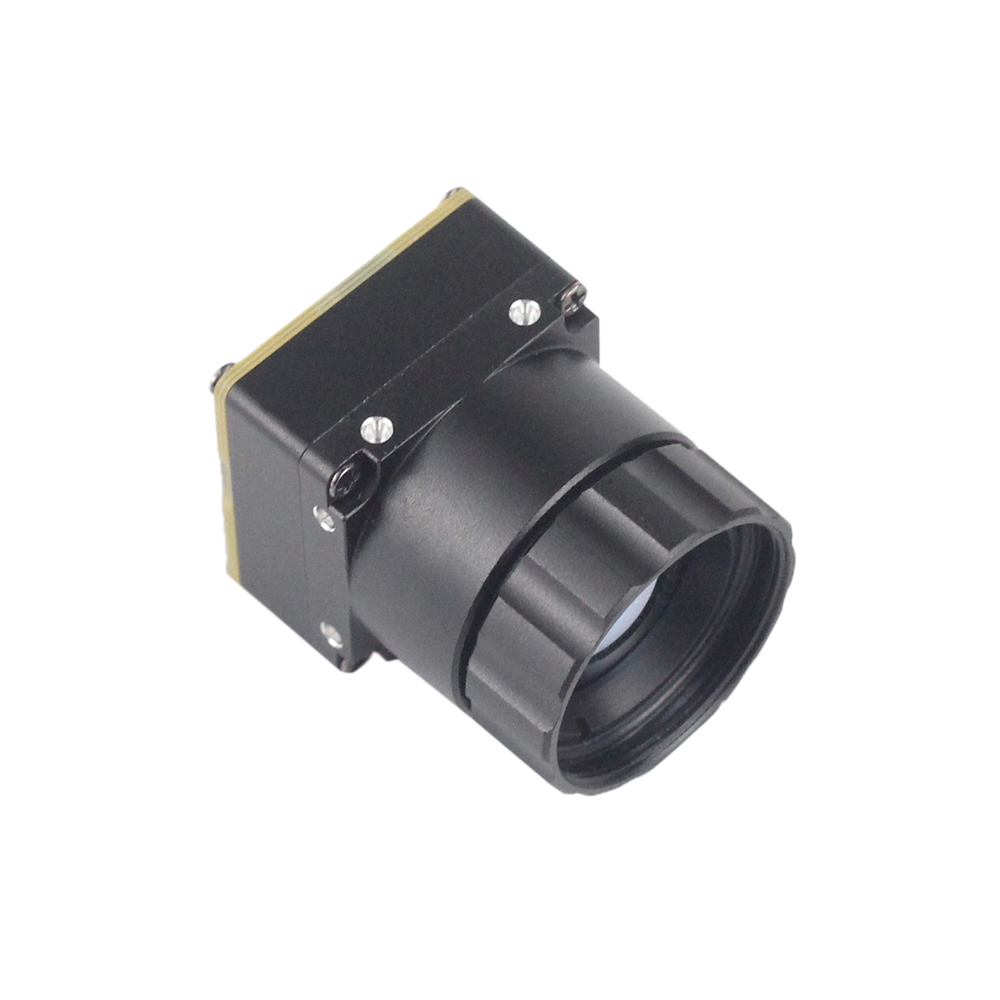
1. The Physics of 256x192 Resolution & Microbolometer Pixel Pitch
The heart of any modern infrared imaging system is the uncooled microbolometer array. To evaluate a thermal camera module 256x192 25mm, we must first look at the focal plane array (FPA) mechanics. Today's industrial sensors primarily rely on either Vanadium Oxide (VOx) or Amorphous Silicon thin films deposited onto a silicon read-out integrated circuit (ROIC). VOx remains the preferred material for professional applications due to its higher temperature coefficient of resistance (TCR), leading to lower Noise Equivalent Temperature Difference (NETD) values and cleaner overall imagery under a wide envelope of operational conditions.
When electromagnetic radiation in the Long-Wave Infrared spectrum (typically 8 to 14 micrometers) strikes the uncooled microbolometer array, the individual vox pixels absorb the thermal energy. This absorption causes a localized temperature change in the active material, which in turn alters its electrical resistance. The ROIC continuously measures these changes in resistance across all 49,152 pixels in a 256x192 matrix, translating them into digital numbers (DN) that form the thermal frame. Because this is a thermionic process rather than a quantum excitation process like cooled MWIR detectors, uncooled VOx sensors require no cryogenic cooling, making them extremely lightweight, power-efficient, and structurally robust.
The Role of Pixel Pitch (12μm vs. 17μm)
Pixel pitch refers to the physical center-to-center distance between adjacent detector elements on the sensor array. For years, 17μm was the industry standard. However, the migration to 12μm pixel pitch technology has fundamentally reshaped the economics and physics of thermal integration. When you reduce the pixel pitch while keeping the array resolution constant, you shrink the physical size of the sensor chip itself. This directly impacts optical magnification, mechanical constraints, and manufacturing costs.
To calculate the physical horizontal and vertical dimensions of the FPA, we use the following equation:
FPA Dimensions = Resolution × Pixel Pitch
Look, let us compare the active areas for a 256x192 FPA across both standards:
- ⚙️ Standard 17μm Pixel Pitch: The active sensor area measures 4.35 mm (Horizontal) by 3.26 mm (Vertical), resulting in a physical diagonal of 5.44 mm.
- ⚙️ Modern 12μm Pixel Pitch: The active sensor area measures 3.07 mm (Horizontal) by 2.30 mm (Vertical), resulting in a physical diagonal of only 3.84 mm.
This physical footprint reduction is key to modern optical configurations. Because the sensor diagonal of a 12μm microbolometer is significantly smaller than its 17μm predecessor, a lens of a given focal length (such as 25mm) will project a narrower field of view or higher magnification on the smaller sensor. Essentially, transitioning to a 12μm pixel pitch allows system engineers to achieve the same telephoto performance using smaller, lighter, and more budget-friendly Germanium lens optics. This reduction in lens size is incredibly valuable for weight-sensitive aerial drone gimbals and hand-held monocular scopes where every gram matters.
Understanding NETD and Thermal Sensitivity
Noise Equivalent Temperature Difference (NETD) is the primary metric used to quantify the thermal sensitivity of an infrared detector. It represents the temperature change of a target that would produce a signal-to-noise ratio equal to unity. Expressed in millikelvins (mK), typical high-performance B2B cores exhibit NETD values of ≤40mK or ≤50mK, calibrated at an aperture of F/1.0 and a nominal target ambient temperature of 300 Kelvin.
A lower NETD provides several distinct advantages in the field:
- ✅ Superior Contrast in Low-Contrast Conditions: On highly uniform thermal days, such as during rainy periods or in high-humidity tropical environments where ambient surfaces stabilize to identical temperatures, a sensitive sensor can easily distinguish fine structural details that would appear as flat gray on high-noise sensors.
- ✅ Lower Spatial Noise: Low NETD values minimize temporal and spatial static noise, ensuring that software-driven edge detection and thresholding algorithms function reliably without processing artifact-laden video streams.
- ✅ Enhanced Object Differentiation: Spotting subtle thermal variations between a target, such as a mammal or engine block, and its background becomes much quicker and more precise, reducing false alarms in automated surveillance loops.
2. Why a 25mm Telephoto Lens Changes the Game: DRI Analysis
A high-performance thermal core is only as powerful as the optical assembly mounted in front of it. While small-focal-length lenses (such as 2mm to 9mm) are highly practical for close-range situational awareness, indoor fire fighting, and wide-angle drone navigation, they are inherently limited for long-distance surveillance and scouting. A wide lens spreads the available pixels of a 256x192 array over a massive spatial field, ensuring that any target at a moderate distance covers only a fraction of a single pixel.
Choosing a high-transmission 25mm telephoto lens changes the mathematical dynamic completely. By narrowing the field of view down to approximately 7.0° × 5.3°, the optical system dramatically improves its Instantaneous Field of View (IFOV). The IFOV defines the physical spatial size projected onto a single pixel at a specific distance, and is computed using the following equation:
IFOV (Radians) = Pixel Pitch (d) / Focal Length (f)
For a modern 12μm pixel pitch sensor paired with a 25mm lens:
IFOV = (12 × 10^-6 m) / (25 × 10^-3 m) = 0.48 milliradians (mrad)
To convert this into a tangible real-world rendering, we calculate the physical area size that a single pixel will monitor at a distance of 1,000 meters:
Spatial Resolution at 1,000m = 1,000m × 0.00048 rad = 0.48 meters (48 centimeters)
This incredibly tight pixel concentration means that at 1,000 meters, an object measuring roughly 1 meter in width will be resolved across at least two full pixels. This level of resolution is a significant game changer compared to wide-angle setups, where a human at 100 meters might fail to register as even a single discrete pixel.
DRI Target Ranges (Johnson's Criteria)
To calculate exact target performance ranges for security networks, UAV design specs, and hunting systems, engineers apply Johnson's Criteria. Under this standard, thermal target acquisition is broken down into three absolute tiers based on active pixels resolved across the critical dimension of a target:
- ⚙️ Detection (2 Pixels): Determining that an object of interest is present in the thermal scene.
- ⚙️ Recognition (8 Pixels): Discerning the class of the object (e.g., distinguishing a human from an animal or a truck from a car).
- ⚙️ Identification (12 Pixels): Deciding specific details of the target (e.g., distinguishing a civil vehicle from a military vehicle, or recognizing a specific human pose).
The table below outlines predicted performance metrics for a 256x192 thermal core with a 12μm pixel pitch paired with a high-transmission 25mm F/1.0 Germanium lens under standard clear atmospheric conditions:
Understanding these optical range dynamics is critical when designing systems meant to operate at high altitudes or over expansive territories. For example, drone developers rely on precise DRI modeling to optimize altitude patterns for automated sweeps. For further details on how drone-based infrared payloads are deployed to monitor vast natural environments, you can review our insights on how UAV thermal imaging technology helps wildlife survey and protection.
3. Digital & Electrical Interfaces: MIPI CSI-2, USB, and CVBS Decoded
When integrating a thermal camera module into an embedded electrical design, selecting the right physical and protocols-based digital or analog interface is crucial. The choice directly affects latency, power consumption, data depth, and physical PCB trace routing complexity.
MIPI CSI-2 (Mobile Industry Processor Interface Camera Serial Interface 2)
For professional systems demanding high-speed, direct SoC interaction with absolute minimum latency, MIPI CSI-2 is the premier standard. This protocol connects physically to the processor utilizing low-voltage differential signaling (LVDS) lines consisting of one clock lane and one or more dedicated data lanes. Because the MIPI interface bypasses intermediate bridge chips, it enables direct register-level communication with the host processor's Image Signal Processor (ISP).
Key highlights of MIPI CSI-2 integration include:
- ✅ Bandwidth & Data Depth: MIPI CSI-2 easily handles uncompressed 14-bit raw radiometric data streams or pre-formatted YUV422 streams at high frame rates (such as 25Hz to 50Hz) with extremely low overhead.
- ✅ Latency Profile: Latency is virtually zero (less than 2 milliseconds), making it highly suited for fast flight-control stabilization loops and target tracking systems.
- ⚙️ Physical Implementation: Due to high-frequency operation, board designers must plan for controlled-impedance differential trace routing ($100\,\Omega$ differential impedance). This physical connection is usually made via advanced micro-coaxial ribbons or highly flexible flex circuits designed by premium suppliers like Amphenol.
USB 2.0 / USB Video Class (UVC)
If rapid prototyping, software cross-compatibility, and ease of installation are top-tier priorities, USB represents the ideal path. Standardized as a USB Video Class (UVC) interface, the module registers directly with host operating systems as a standard driverless webcam.
Key highlights of USB integration include:
- ✅ High Software Portability: UVC compatibility ensures the thermal camera module can run immediately on Windows, Linux, Android, or macOS environments without requiring system-level custom driver development.
- ⚙️ Integration Overhead: Implementing USB requires an on-board USB physical transceiver chip on the camera module's PCB. This slightly increases the physical footprint, heat output, and electrical power draw compared to raw MIPI designs. If you want to explore the technical advantages of this interface further, check out our guide on high-resolution USB thermal camera modules and custom OEM cores for PCBA.
CVBS (Composite Video Baseband Signal)
CVBS remains highly relevant in tactical scopes and legacy drone systems due to its simplicity, resilience, and ease of physical routing.
Key highlights of CVBS integration include:
- ✅ Analog Legacy Output: Transmits standard analog composite video signals (either NTSC or PAL format) over $75\,\Omega$ coaxial lines or simple twisted pairs, making it highly compatible with micro OLED displays.
- ✅ RF Downlink Performance: CVBS plugs directly into standard analog video transmitters (VTX). Unlike digital links that completely drop packets and freeze during interference, analog composite transmissions degrade gracefully with distance, ensuring the visual feed remains readable during long-distance or high-interference flights. Understanding these analog paths is critical, particularly when assessing the principle and function of drone image transmission modules.
4. Edge AI Integration & SDK Deployment on SBCs
Industrial automation, smart security, drone tracking, and agricultural monitoring setups increasingly require localized, edge-computing processing. Instead of utilizing precious radio band transmission links to send raw feeds back to a ground station, modern architectures perform target extraction and temperature calculations right at the source using Single Board Computers (SBCs) such as NVIDIA Jetson (Orin Nano/NX) or the Raspberry Pi family.
Handling Radiometric Data Arrays
A standard thermal video payload is not just a visual picture; it is an array of measurement points. For a 256x192 array, the camera module outputs 49,152 discrete temperature data points per frame, typically encoded at 14 bits per pixel. In a radiometric stream, the raw pixel digital value (Digital Number, or DN) is mapped directly to absolute temperature using linear scale factors.
The basic linear calculation to convert raw microbolometer data to temperature values is defined by:
T_target = (Pixel Value × Scale Factor) - Offset
This allows designers to extract exact Celsius, Fahrenheit, or Kelvin values for any pixel coordinate in real time. The following Python script demonstrates how an integrated Linux-based SBC parses raw radiometric buffers:
import numpy as np

def process_radiometric_frame(raw_buffer, scale_factor=0.01, offset_k=273.15):
    """
    Converts 14-bit raw thermal data to physical degrees Celsius.
    Assumes a standard 256x192 sensor array.
    """
    # Cast 1-dimensional raw byte array to 16-bit unsigned integers
    frame_16bit = np.frombuffer(raw_buffer, dtype=np.uint16)

    # Reshape array to target resolution (192 rows, 256 columns)
    thermal_matrix_raw = frame_16bit.reshape((192, 256))

    # Calculate temperature in Kelvin and convert to Celsius
    temp_celsius = (thermal_matrix_raw * scale_factor) - offset_k
    return temp_celsius

# Simulated raw 14-bit payload array
raw_data_mock = bytearray([0x5A, 0x30] * (256 * 192 * 2))
frame = process_radiometric_frame(raw_data_mock)
print(f"Center pixel temperature: {frame[96, 128]:.2f} °C")
Implementing Edge AI Models
Once raw pixels have been decoded and normalized, they can feed directly into convolutional neural networks (CNNs) trained specifically on infrared imagery. Models like YOLO (You Only Look Once) or MobileNet run natively on edge accelerators to:
- ⚙️ Differentiate Heat Signatures: Distinguish between human intruders, wild animals, vegetation reflections, and false heat sources based on geometric profiles and heat intensities.
- ⚙️ Isolate Hot Spots: Instantly tag anomalies such as failing power distribution line connectors, electrical substation hazards, agricultural crop stress, or forest fire starts.
- ⚙️ Execute Kinematic Tracking Loops: Pass spatial bounding-box coordinates directly to drone autopilot flight controllers, automatically panning localized gimbals to keep target signatures center-frame.
5. Curated B2B Product Catalog & Specs Showcase
To assist B2B purchasing agents and system developers in sourcing reference hardware, the following table evaluates professional uncooled infrared thermal modules. These options provide exceptional performance configurations across MIPI, USB, and CVBS interfaces.
Deep Product Spotlights
1. Uncooled Infrared Mipi Mini2 Thermal Imaging Camera Module
Designed specifically for micro air vehicle (MAV) applications, this series delivers highly optimized weight profiles without sacrificing thermal sensitivity. It features sharp and crisp image presentation, compact size, and low cost.
This module features real-time flat field correction (FFC) routines, on-board dynamic range enhancement (DDE), and extremely low self-heating profiles to prevent thermal drift inside enclosed gimbal casings. It is highly optimized for direct integration onto brushless 2-axis and 3-axis mini drone gimbals.

View Product Details & Pricing ➔
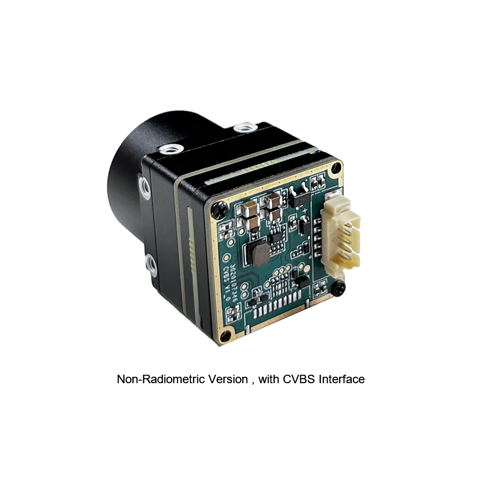
2. Uncooled Mini 384x288 Thermal Camera Module for Drones
The MINI series infrared thermal imaging temperature measurement module is a high-precision, small-sized, and universal online temperature measurement infrared thermal imager. It uses high-quality detectors, high resolution, stable performance, and powerful functions. It is equipped with multiple interfaces, making it a preferred product in application fields such as machine vision, safety inspection, intelligent manufacturing, equipment maintenance, and robot drone airborne systems.
This module features an advanced aluminum alloy housing that functions as an integrated heat sink, shielding the internal detector from ambient electronic noise while maintaining radiometric temperature calibration stability. It is highly resistant to extreme shock and structural environment vibrations.
View Product Details & Pricing ➔
6. Implementation Blueprint: DIY Thermal Scope & Drone Payload
For hardware developers building a field-ready DIY thermal scope or an integrated drone platform, this integration blueprint outlines the standard layout requirements across power, mechanical design, and dynamic signal routing.
A. Power Delivery & Filtering
Microbolometer arrays are highly sensitive to electrical noise. High-frequency noise generated by brushless ESCs (Electronic Speed Controllers) or wireless transmitters can easily corrupt the microbolometer's power rail, producing rolling vertical lines or static snow in the infrared video feed. To prevent this, developers should implement a multi-stage filtering design:
- ⚙️ Low-Dropout Regulator (LDO): Power the thermal camera module using a dedicated, high power supply rejection ratio (PSRR) linear regulator, isolated completely from the digital power planes.
- ⚙️ Decoupling Capacitors: Place decoupling capacitors ($0.1\mu\text{F}$ and $10\mu\text{F}$ ceramic types) as close to the camera module's input power pins as physically possible to smooth out high-frequency ripple.
B. High-Reliability Electrical Connections
Drones and firearm-mounted scopes expose electronic components to violent G-forces and vibrations that can quickly dislodge connectors:
- ⚙️ Rugged Cabling: Utilize high-density flex-rigid PCB transitions or locking micro-coaxial connectors (such as the ruggedized designs engineered by Amphenol) to prevent connection errors during operation.
- ⚙️ Stress Relief: Apply specialized electronics adhesive or high-reliability polyimide kapton tape over locking connector tabs on rugged assemblies to prevent physical connector pins from backing out under heavy recoil or rapid flight movements.
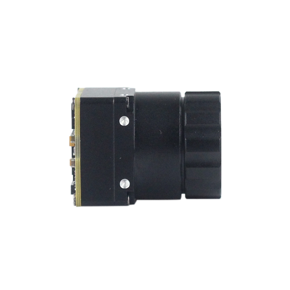
C. Mechanical Thermal Dissipation
Because uncooled VOx microbolometers calculate temperatures based on changes in sensor resistance, maintaining a stable ambient temperature around the sensor frame is absolutely essential. Heat bleeding from on-board microprocessors or video transmitters can cause localized thermal gradients across the core, leading to image distortion or "shading" errors.
- ⚙️ Thermal Isolation: Mount the core using non-conductive nylon or carbon-fiber standoffs to block heat transmission from neighboring processing boards.
- ⚙️ Radiator Path: Ensure the core's metal housing is physically coupled to an external aluminum or copper heat sink with high-quality silicone thermal pads, allowing passive airflow or active downwash from drone propellers to stabilize the module's operating temperature.
7. Deep-Dive Technical FAQ
Is a 256x192 resolution with a 25mm lens good enough for outdoor scanning and DIY thermal scopes?
How do professional-grade uncooled thermal modules compare to budget consumer thermal dongles?
Can these uncooled thermal camera modules be integrated directly into SBCs like Raspberry Pi or Jetson Nano?
📚 References & Further Reading
- Industry Standard: Raspberry Pi Single-Board Computer Architectures
- Hardware Components: Amphenol High-Reliability Electrical Connections
- Related Guide: UAV Thermal Imaging Technology Helps Wildlife Survey and Protection
- Related Guide: Principle and Function of Drone Image Transmission Modules
- Related Guide: High-Resolution USB Thermal Camera Module Custom OEM Cores for PCBA





