Thermal Imaging Camera Guide: Resolution, Sensor Specs & Core Modules Explained
2026年10月19日
Thermal Imaging Cameras Guide: Resolution, Edge AI & Industrial Specs Unlocked
2026年10月20日
Best Thermal Imager Guide: Budget Gadgets vs. Industrial AI LWIR Modules
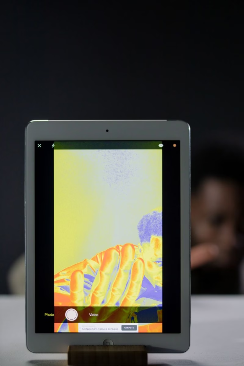
Modern industrial automation, predictive maintenance, and autonomous unmanned systems rely heavily on long-wave infrared (LWIR) sensing to extract actionable thermographic signatures where visible-spectrum optical systems completely fail. However, the commercial proliferation of consumer-grade, sub-$400 thermal imager gadgets—often packaged as smartphone dongles or hobbyist pistol-grip tools—has created severe confusion among system integrators, optical engineers, and procurement directors. While these consumer devices can visualize gross thermal differentials (such as drafty home window seals or severely overheated domestic circuit breakers), deploying them inside industrial process pipelines, high-vibration drone gimbals, or automated optical inspection (AOI) lines introduces critical blind spots, false positives, and catastrophic operational downtime.
Industrial thermography demands microbolometer arrays engineered with unyielding radiometric stability, deterministic latency, ultra-low Noise Equivalent Temperature Difference (NETD), and edge-AI compute capabilities. As optical payloads shrink across defense, robotics, and smart infrastructure, the boundary between standalone diagnostic tools and embedded sensor cores has shifted decisively toward uncooled Vanadium Oxide (VOx) OEM modules. This guide establishes a rigorous engineering benchmark contrasting entry-level thermal consumer gadgets against edge-integrated industrial LWIR modules, equipping engineering leads with the technical specifications, optical physics parameters, and integration architectures necessary to execute high-ROI deployments.
Table of Contents
- 👉 The Physics of Thermal Imaging: From Planck's Law to Uncooled VOx Microbolometers
- 👉 Architectural Breakdown: Cheap Consumer Dongles vs. Industrial LWIR OEM Modules
- 👉 Next-Gen Intelligence: Edge AI, Thermal Computer Vision, and Autonomous Telemetry
- 👉 Benchmark Comparison: Industrial LWIR Sensor Engines in the Field
- 👉 Procurement & System Integration Checklist for OEM Engineers
- 👉 Industrial Thermography & Engineering FAQ
The Physics of Thermal Imaging: From Planck's Law to Uncooled VOx Microbolometers
Every physical object with a thermodynamic temperature above absolute zero (0 Kelvin / -273.15°C) continuously emits electromagnetic radiation generated by the fundamental kinetic motion of its charged subatomic particles. The spectral distribution and intensity of this emitted flux are governed by Planck's Radiation Law, which describes the spectral radiance of a blackbody as a function of absolute temperature and wavelength:
B(λ, T) = (2 · h · c2) / [ λ5 · (exp((h · c) / (λ · kB · T)) - 1) ]
Where h represents Planck's constant (6.62607015 × 10⁻³⁴ J·s), c is the speed of light in vacuum (2.99792458 × 10⁸ m/s), kB is the Boltzmann constant (1.380649 × 10⁻²³ J/K), λ denotes the wavelength of emitted radiation, and T is absolute temperature in Kelvin. Integrating Planck's spectral distribution over all radiating wavelengths yields the Stefan-Boltzmann Law:
W = ε · σ · T4
Here, radiant emittance W (W/m2) is proportional to target surface emissivity (ε), the Stefan-Boltzmann constant (σ = 5.670374 × 10⁻⁸ W·m-2·K-4), and the fourth power of target temperature. By applying Wien's Displacement Law (λmax · T ≈ 2898 μm·K), one observes that terrestrial objects operating within conventional industrial temperature regimes (-40°C to +650°C, or 233.15 K to 923.15 K) exhibit peak electromagnetic emission strictly within the Long-Wave Infrared (LWIR) band spanning from 8 to 14 micrometers (μm).
The Earth's atmosphere introduces severe absorption bands due to atmospheric moisture (H2O vapor), carbon dioxide (CO2), ozone (O3), and particulate aerosol scattering. Fortunately, the 8 to 14 μm LWIR atmospheric transmission window demonstrates minimal absorption losses compared to the Short-Wave Infrared (SWIR, 1.4 to 3 μm) and Mid-Wave Infrared (MWIR, 3 to 5 μm) spectra over moderate standoff ranges, rendering LWIR uncooled systems uniquely resilient against smoke, light atmospheric dust, and ambient humidity.
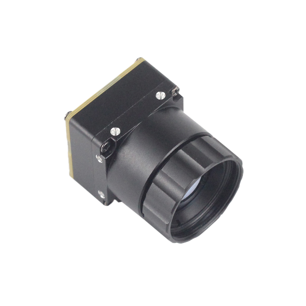
Translating this incident radiant flux into measurable electrical telemetry without bulky, power-hungry cryogenic Stirling cooling engines requires an uncooled microbolometer Focal Plane Array (FPA). In an industrial thermal imager, the signal pipeline functions across five discrete physical stages:
- ⚙️ Spectral Capture: Incident 8–14 μm photon flux travels through an anti-reflective coated optical aperture and impinges upon an array of micro-machined detector pixels suspended in high vacuum. This vacuum environment eliminates conductive and convective heat transfer through surrounding gases, ensuring that radiant absorption directly drives detector heating.
- ⚙️ Micro-Bridge Absorption: Each pixel consists of a microscopic, free-standing membrane (typically 12 μm × 12 μm in modern architectures) fabricated from a thermally sensitive material suspended over a silicon readout substrate by dual micro-machined silicon nitride anchor legs. These legs isolate the membrane thermally, minimizing heat leakage conductance ($G_{th}$) back into the substrate and setting the thermal time constant ($\tau = C_{th} / G_{th} \approx 8\text{ to }12\text{ ms}$).
- ⚙️ Resistance Transduction (VOx vs. α-Si): When the membrane absorbs incident infrared radiance, its temperature rises by mere millikelvins. Industrial thermal imager modules exclusively deploy Vanadium Oxide (VOx) thin-film thermistors rather than amorphous Silicon (α-Si). VOx exhibits a vastly superior Temperature Coefficient of Resistance (TCR), consistently offering -2% to -3% per Kelvin shift, along with markedly lower $1/f$ flicker noise characteristics. This ensures a superior signal-to-noise ratio (SNR) that defines the core metric of thermal sensitivity: Noise Equivalent Temperature Difference (NETD).
- ⚙️ Readout Integrated Circuit (ROIC) Sampling: The underlying CMOS ROIC multiplexer applies an ultra-stable bias voltage or pulse current across the pixel array. As VOx resistance changes, minute micro-voltage fluctuations are captured, amplified by integrated low-noise transimpedance amplifiers, and digitized using on-die 14-bit or 16-bit Analog-to-Digital Converters (ADCs).
- ⚙️ Radiometric Correction Pipeline: Raw digital counts pass to an internal FPGA or digital signal processor (DSP) which continuously applies multi-point Non-Uniformity Correction (NUC), bad pixel replacement (BPR), housing temperature calibration curves, and spatial filtering before streaming deterministic radiometric tensors to downstream edge processors.
Crucially, conventional silicate glass substrates (such as standard borosilicate crown BK7 or fused silica) exhibit near-total opacity within the LWIR spectral transmission band. An industrial thermal imager demands specialized optical lenses fabricated from single-crystal Germanium (Ge) or high-purity Chalcogenide glass alloys (e.g., Ge-Sb-Se or As-Se-Te matrices). Optical manufacturers such as LightPath Technologies pioneer diamond-turned chalcogenide and molded aspheric optical geometries coated with broad-band anti-reflective (BBAR) diamond-like carbon (DLC) films. These optical assemblies maintain high transmission efficiencies exceeding 94% across the 8–14 μm band while physically withstanding abrasive industrial airborne particulates, salt spray, and extreme thermal shock.
When selecting optical assemblies, lens transmission, chromatic dispersion, and thermal focus shift ($dn/dT$) cannot be overlooked. Germanium possesses an unusually high refractive index (~4.00 at 10 μm), allowing for thin, high-numerical-aperture lens designs. However, its temperature coefficient of refractive index ($dn/dT \approx 3.96 \times 10^{-4}\text{ K}^{-1}$) means standard uncompensated Germanium optics de-focus rapidly when operating across wide ambient sweeps. Industrial-grade modules incorporate mechanically or optically athermalized lens assemblies, combining Germanium with specialized Chalcogenide elements to preserve the optical Modulation Transfer Function (MTF) from -40°C up to +80°C without manual refocusing.
Architectural Breakdown: Cheap Consumer Dongles vs. Industrial LWIR OEM Modules
The industrial instrumentation market has seen an influx of low-cost, consumer-grade thermal imager gadgets. Primarily targeted at DIY home inspectors, smartphone enthusiasts, and hobbyists, these sub-$400 accessories are fundamentally engineered with cost-optimized compromises that disqualify them from mission-critical automation, factory process monitoring, or airborne drone payloads. To understand why these gadgets fail in rugged environments, one must analyze their mechanical, electrical, and optical architectural disparities against true industrial OEM cores.
| Architectural Attribute | Consumer Thermal Dongle / Gadget | Industrial OEM LWIR Core Module |
|---|---|---|
| Native Sensor Resolution | 80×60 to 160×120 pixels (interpolated via app software) | 384×288 up to 1280×1024 native megapixel arrays |
| Pixel Pitch & Lithography | 17 μm to 25 μm (large pixel footprint, bulky focal stack) | Advanced 12 μm VOx lithography (high SWaP-C efficiency) |
| Thermal Sensitivity (NETD) | ≥ 70 mK to 150 mK (high noise floor, coarse delta capture) | ≤ 30 mK to 40 mK (resolves 0.03°C micro-gradients) |
| Frame Rate & Latency | ≤ 9 Hz (software-throttled, severe motion blurring) | 25 Hz / 30 Hz / 50 Hz / 60 Hz real-time low-latency telemetry |
| Drift Calibration / NUC | Shutterless digital guess or erratic clicking micro-shutter | Precision solenoid mechanical shutter + active temperature LUTs |
| Data Output Format | Compressed 8-bit RGB / YUV stream (color palette only) | Raw uncompressed 14-bit / 16-bit radiometric linear output |
| Operating Temperature Range | 0°C to +35°C (drifts violently outside room temperature) | -40°C to +80°C industrial temperature hardened rating |
1. Spatial Resolution, Pixel Pitch, and IFOV Dynamics
The resolving power of an optical thermal sensor is bounded by its Instantaneous Field of View (IFOV). Mathematically, IFOV represents the angular footprint subtended by a single physical detector pixel on the target scene, calculated as:
IFOV = Pixel Pitch (d) / Focal Length (f)
When an engineer deploys a cheap 80×60 consumer thermal imager equipped with a 17 μm pixel pitch and a wide-angle 3 mm focal length lens to inspect a mission-critical motor control center (MCC), the IFOV is roughly 5.66 milliradians. At a modest working distance of 3 meters, a single pixel covers an area of roughly 17 mm × 17 mm. If a 0402 surface-mount resistor, an insulated terminal lug, or an IGBT bonding wire begins to fail and overheats within a 1.5 mm area, its radiant thermal energy is averaged across the entire 17 mm pixel footprint alongside the ambient cold enclosure plate. The resultant measurement shows an attenuated, false rise of only +4°C above ambient, while the actual junction is actively melting at +125°C. This physical phenomenon—known as the optical spot-size ratio limit—causes disastrous diagnostic oversights in electrical infrastructure.
Conversely, deploying a high-resolution industrial OEM thermal imager (such as a native 1280×1024 or 384×288 core utilizing modern 12 μm lithography paired with an athermalized narrow-field Germanium lens) slashes the IFOV to sub-milliradian boundaries. This guarantees that targets satisfy the classical Johnson criteria for precision optical inspection, providing true detection, recognition, and quantitative radiometric identification without spatial blur. For a broader analysis of how resolution boundaries impact system functionalities, consult this comprehensive review on thermal imaging product functionalities across automation environments.
2. Thermal Sensitivity (NETD) and Signal Degradation
Noise Equivalent Temperature Difference (NETD) defines the minimum temperature differential that the thermal imager can reliably resolve against its own electronic noise floor. Expressed in millikelvins (mK), lower values represent superior sensitivity. Consumer gadgets frequently rate their NETD at ≥ 70 mK to 100 mK at room temperature (+25°C). When subjected to industrial production lines featuring low thermal contrast—such as detecting subtle laminar cooling variations in extruded carbon-fiber composites, identifying early sub-surface moisture ingress in aviation wings, or spotting faint fluid boundary lines inside vacuum-insulated chemical pipelines—the subtle 0.05°C temperature signature is completely swallowed by the detector's internal electronic thermal noise.
Industrial VOx OEM cores achieve verified NETD figures below 30 mK to 40 mK (f/1.0, 300 K). This ultra-low noise floor isolates minute thermodynamic deltas, enabling early fault detection weeks before an unbalance, friction bearing breakdown, or metallurgical stress crack manifests as an obvious, macroscopic temperature anomaly.
3. Real-Time Dynamic Telemetry vs. 9 Hz Export Restrictions
Most commercial thermal dongles operate at ≤ 9 Hz frame rates to bypass International Traffic in Arms Regulations (ITAR) and multilateral Wassenaar Arrangement export control restrictions. While a 9 Hz refresh rate is sufficient for an electrician taking a static snapshot of an unmoving breaker panel, it is useless in industrial automation or autonomous robotics. A drone flying at 12 m/s surveying high-voltage power lines covers 1.33 meters between each captured thermal frame at 9 Hz, introducing massive motion blur, rolling-shutter artifacts, and missing intermittent hot-spot anomalies entirely. Similarly, on high-speed automated web inspection lines moving at hundreds of parts per minute, a 9 Hz sensor captures only motion-smeared, non-radiometric streaks.
Industrial cores output native 25 Hz, 30 Hz, 50 Hz, or 60 Hz full-frame data over deterministic buses, ensuring that dynamic machine processes, robotic manipulators, and high-speed drone gimbals capture razor-sharp spatial frames without temporal aliasing.
Next-Gen Intelligence: Edge AI, Thermal Computer Vision, and Autonomous Telemetry
The role of the thermal imager has evolved beyond human-in-the-loop diagnostic monitoring. In state-of-the-art Industry 4.0 deployments, a thermal imager acts as an edge-computing perceptual node feeding continuous radiometric data into computer vision (CV) and artificial intelligence (AI) inference engines. When transitioning from visible-light RGB inspection to LWIR computer vision, optical engineers encounter a profound advantage: thermal imaging is completely invariant to dynamic ambient lighting, backlighting shadows, optical glints, solar reflections, and visible smoke or particulate obscurants.
However, running deep neural networks on thermal streams introduces unique architectural requirements. Consumer gadgets output compressed 8-bit color-mapped visualizations (e.g., JPEG or MP4 compressed Ironbow, Rainbow, or White-Hot palettes). Once a thermal sensor stream is compressed into an 8-bit palette, the underlying quantitative radiometric calibration is permanently destroyed. The downstream algorithm only perceives normalized RGB pixel luminance (0–255), completely uncoupled from absolute target temperature.
True industrial OEM modules transmit uncompressed 14-bit or 16-bit linear digital radiometric telemetry. In this pipeline, each pixel value corresponds directly to a digital number (DN) proportional to raw incident flux, mapping precisely to absolute target temperature via the fundamental calibration transfer equation:
Ttarget = [ (DN - Osystem) / (R · τatm · ε) + (1 - ε)/ε · Trefl4 ]1/4
Where Osystem represents the internal camera/housing thermal offset, R denotes radiometric responsivity, τatm is the atmospheric transmission coefficient, ε is surface emissivity, and Trefl is background reflected ambient temperature. By feeding raw 14-bit tensors straight into high-performance edge compute platforms—such as the NVIDIA Jetson Orin Nano/AGX, Rockchip RK3588, or custom Xilinx Zynq UltraScale+ MPSoCs—engineers can run custom convolutional neural networks (such as YOLOv8-Thermal, SegNet, or Mask R-CNN) that execute complex operational logic:
- ✅ Automated Isothermal Segmentation: Algorithms extract multi-region thermal boundaries, autonomously identifying defective photovoltaic cells undergoing reverse-bias degradation across massive utility-scale solar farms.
- ✅ Dynamic Delta-T/Delta-t Calculation: Neural networks track the temporal rate of temperature rise (∂T/∂t) across critical CNC spindle bearings or turbine housings, immediately issuing CAN-bus or industrial Ethernet shutdown triggers if transient heating profiles indicate lubrication failure.
- ✅ Autonomous Multi-Spectral Fusion: Airborne perception engines combine 14-bit LWIR frames with high-resolution RGB feeds and 3D LiDAR point clouds to deliver all-weather autonomous navigation, situational awareness, and automated infrastructure inspection, as documented in this engineering overview of industrial thermal imaging modules for drones.
- ✅ Thermal Detail Enhancement & Dynamic Range Compression: Digital Detail Enhancement (DDE) and bilateral filtering algorithms separate broad thermal baselines from high-frequency edge details. This preserves critical textural information without blowing out high-temperature zones or clipping cold backgrounds into pure black.
For engineering teams working under strict Size, Weight, and Power (SWaP) constraints, optimizing embedded AI pipelines is paramount. Reviewing the empirical benchmark analysis in this MINI 640 thermal camera module performance evaluation illustrates how high-efficiency microbolometers deliver uncompromised frame rates without thermal saturation of host embedded processors.
Benchmark Comparison: Industrial LWIR Sensor Engines in the Field
To ground these system engineering principles in production-ready hardware, we evaluate two high-performance uncooled Vanadium Oxide (VOx) sensor engines engineered for mission-critical deployments. Sourcing these certified cores through vetted global supply channels such as KUYANG ensures end-to-end traceability, deterministic batch-to-batch calibration, and long-term hardware availability for embedded OEM production lifecycles.
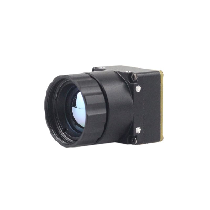
Product Showcase 1: Uncooled Mini 384*288 Thermal Camera Module For Drones
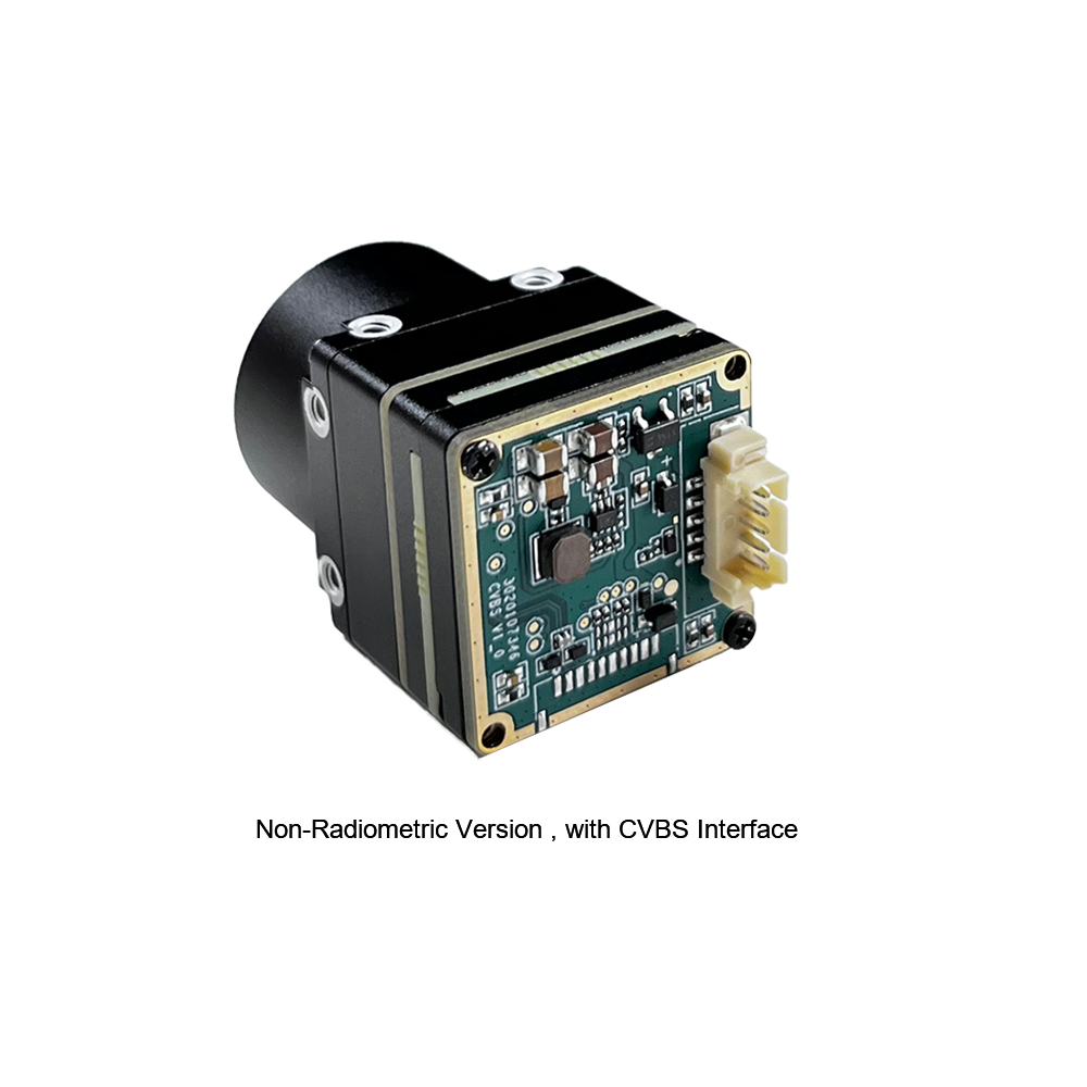
The MINI series infrared thermal imaging temperature measurement module is an ultra-compact, high-precision, universal online temperature measurement thermal imager. Engineered specifically for SWaP-constrained airborne platforms and robotic vision, this engine utilizes high-quality VOx focal plane arrays delivering exceptionally stable operational performance, high spatial resolution, and comprehensive radiometric analytics. The module is fully equipped with versatile interface options, making it the preferred product in application fields such as machine vision, automated safety inspection, intelligent manufacturing, equipment predictive maintenance, and autonomous drone airborne gimbals.
| Core Specification | Engineering Parameter |
|---|---|
| Detector Resolution | 384 × 288 native active pixels (110,592 spatial data points) |
| Sensor Technology | Uncooled Vanadium Oxide (VOx) Microbolometer FPA |
| Spectral Range | 8 to 14 μm (Long-Wave Infrared band) |
| Electrical & Video Interfaces | CVBS Analog video, Industrial USB, Low-Latency Digital Stream |
| Form-Factor Architecture | Ultra-miniaturized lightweight footprint engineered for drone gimbals |
| Primary Integrations | Machine vision, airborne inspection, mobile robotics, predictive maintenance |
Product Showcase 2: High Resolution Uncooled Infrared 1280*1024 Thermal Imaging LWIR Camera
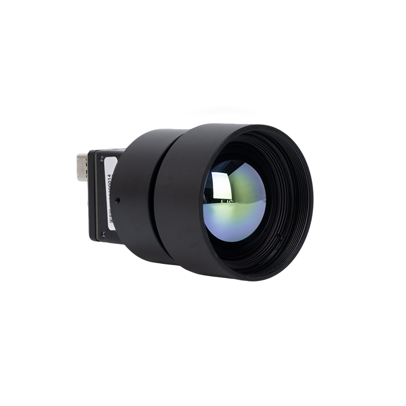
The PRSE5-1280 High Resolution Uncooled Infrared 1280×1024 Thermal Imaging LWIR Camera represents the pinnacle of long-wave infrared spatial acuity. Engineered for demanding industrial machine vision, automated factory surveillance, and long-range infrastructure security, this camera core features an expansive 1.3-megapixel detector array paired with a precision diamond-turned 25mm prime Germanium optical lens stack. It delivers an unprecedented level of granular thermographic detail, allowing system architects to resolve microscopic electronic flaws and wide-area industrial perimeter incursions with equal fidelity.
| Core Specification | Engineering Parameter |
|---|---|
| Megapixel Resolution | 1280 × 1024 pixels (1,310,720 native active detector elements) |
| Optical Configuration | Factory-integrated 25mm prime athermalized Germanium lens stack |
| Spectral Passband | 8 to 14 μm (LWIR uncooled operational regime) |
| Sensor Core Architecture | Ultra-low NETD uncooled VOx microbolometer focal plane array |
| System Enclosure | Ruggedized industrial CNC-machined alloy housing with dynamic NUC |
| Target Deployments | High-precision AOI lines, critical border monitoring, perimeter defense, utility grids |
Procurement & System Integration Checklist for OEM Engineers
Embedding a thermal imager into a production line, an aerospace gimbal, or a certified industrial product demands rigorous cross-disciplinary engineering validation. Unlike off-the-shelf visible spectrum webcams, thermal microbolometers are highly sensitive to external thermodynamic fluctuations, structural vibrations, and electromagnetic coupling. System architects should evaluate five critical engineering criteria before locking down hardware bill-of-materials (BOM):
1. Optical Standoff, IFOV, and Target Geometry Matching
System architects must calculate the required Instantaneous Field of View (IFOV) to ensure the target critical dimension covers a sufficient number of pixels. Following classical target acquisition criteria:
- ⚙️ Detection (1.5–2 line pairs across critical dimension): Sufficient only to flag the presence of an anomalous thermal signature against the background.
- ⚙️ Recognition (6 line pairs): Required to discern whether the hot signature is an overheated transformer bushing or an ambient solar reflection off a metallic chassis.
- ⚙️ Identification & Quantitative Radiometry (12+ line pairs): Mandatory if the system relies on pixel values to trigger automated shutdown safety interlocks.
For close-up printed circuit board inspection (0.05 m to 0.5 m standoff), pair high-resolution cores with specialized macroscopic Germanium optics capable of sub-25 μm spot sizes. For broad perimeter surveillance or aerial transmission line auditing (50 m to 1000 m+ standoff), deploy narrow-FOV objectives (focal lengths ≥ 25 mm to 50 mm) like those integrated on the High Resolution 1280×1024 engine.
2. Dynamic Non-Uniformity Correction (NUC) and Thermal Shock
Because uncooled microbolometers drift dynamically as ambient and internal temperatures fluctuate, the module's thermal drift compensation mechanism is a primary reliability factor. Consumer units often use "shutterless" software heuristics that freeze or miscalculate pixel gain when ambient temperatures sweep rapidly. Industrial OEM cores integrate precision mechanical shutter flags that periodically actuate against a uniform internal reference plate, refreshing offset correction vectors. Ensure that the core's firmware exposes fine-grained API hooks allowing your host system to inhibit NUC shutter clicks during critical time windows (such as during a critical drone landing phase or high-speed automated part pass) to prevent frame dropouts.
3. Electrical Bus Architecture & Latency Profiles
Select an interface that matches your compute architecture's physical layout and throughput demands:
- ⚙️ CVBS Analog Composite: Provides zero-latency transmission across legacy tactical modems, analog telemetry downlinks, and compact FPV monitors. Ideal for pilot-in-the-loop drone maneuvering.
- ⚙️ Direct MIPI-CSI2 / Parallel CMOS: Eliminates conversion ICs, feeding raw 14-bit data directly into host SoC memory via Direct Memory Access (DMA). This minimizes power draw and processing overhead on edge AI devices.
- ⚙️ GigE Vision / USB3 Vision: Complies with AIA industrial standards for plug-and-play machine vision cells, providing deterministic packet delivery, GenICam parameter control, and standard cable runs exceeding 50 to 100 meters.
4. Enclosure Heat Transfer and Electromagnetic Interference (EMI)
VOx microbolometers operate by measuring minute temperature rises inside suspended micro-bridges. If the sensor is mounted adjacent to high-power electronics—such as a 25W GPU accelerator, a switched-mode power supply (SMPS), or high-torque stepper motors—parasitic heat transfer will create uneven thermal gradients across the sensor array, resulting in fixed-pattern noise (FPN) and vignetting. Industrial integrators must isolate the microbolometer thermally using conductive copper/graphite heat paths that conduct host heat away to an exterior chassis, while maintaining appropriate Faraday shielding to prevent high-frequency RF ripple from corrupting sensitive analog ROIC circuits.
5. Long-Term Radiometric Calibration & Environmental Sealing
An industrial radiometric sensor must maintain its calibration accuracy (±2°C or ±2%) over years of exposure to broad ambient sweeps. Cheap consumer gadgets rely on basic factory room-temperature single-point calibrations that lose accuracy within months of exposure to solar loading or winter conditions. Industrial OEM cores undergo rigorous climate-chamber blackbody calibrations across dozens of target temperatures and housing ambient steps (-20°C to +60°C). When choosing enclosures, demand IP67 or IP68 environmental sealing with Germanium protective front windows finished with diamond-like carbon (DLC) coatings to prevent transmission degradation caused by chemical washdowns, abrasive dust, and salt-fog atmosphere.
Industrial Thermography & Engineering FAQ
Are budget sub-$400 thermal cameras actually worth it for electronics repair or industrial use?
Can I integrate a thermal imager module into custom drone payloads or robotic systems?
What makes an industrial AI thermal imager superior to standard handheld tools?
How does pixel pitch (12µm vs. 17µm) affect lens focal length and optical payload weight?
📚 References & Further Reading
- Industry Standard: Certified uncooled thermal modules and supply-chain logistics provided via KUYANG.
- Industry Standard: Advanced infrared chalcogenide and germanium optical design methodologies by LightPath Technologies.
- Related Guide: Explore critical functional differentiators in our analysis of thermal imaging product functionalities across industrial systems.
- Related Guide: Review autonomous robotic aerial integrations in our breakdown of industrial thermal imaging modules for drones.
- Related Guide: Examine SWaP-C optimization and empirical detector benchmarks in the MINI 640 thermal camera module performance evaluation.