Infrared Thermal Camera Guide: Sensor Tech, Real Resolution & Industrial Buying Tips
2026年10月21日
High-Resolution IR Thermal Camera Modules: Complete Industrial OEM Buying Guide
2026年10月22日
Handheld Thermal Camera Guide: Sensor Specs, Field Performance & Pro Selection
Modern predictive maintenance, electrical condition monitoring, and industrial infrastructure assessments rely heavily on non-contact thermography to diagnose systemic anomalies long before catastrophic hardware failure manifests. A contemporary handheld thermal camera is fundamentally distinct from an entry-level visual thermometer. In professional environments, it functions as a calibrated optoelectronic radiometer that unites an uncooled focal plane array (UFPA), specialized infrared transmissive optics, high-throughput digital signal processing, and low-power edge compute pipelines into a single ergonomic instrument. Selecting the appropriate thermal imager requires navigating intricate engineering trade-offs between detector material physics, spatial versus thermal resolution, non-uniformity correction (NUC) algorithms, and optical dispersion constraints across varied environmental envelopes.
As plant reliability teams, field diagnosticians, and OEM design engineers transition away from consumer-grade diagnostic accessories toward dedicated handheld imagers and modular optical engines, procurement criteria have grown significantly more rigorous. Specifying an instrument now requires engineers to evaluate parameters such as Noise Equivalent Temperature Difference (NETD), Instantaneous Field of View (IFOV), and modern Long-Wave Infrared (LWIR) pixel pitches down to 12μm. This technical guide breaks down core sensor architectures, optics fundamentals, spatial measurement dynamics, enterprise-grade integration frameworks, and field-proven hardware modules to establish a definitive technical benchmark for plant engineers, reliability managers, and OEM system integrators.
Field diagnostics present demanding operational challenges that laboratory instruments never encounter. Real-world surfaces exhibit varied emissivity values, convective wind currents disrupt localized surface temperatures, and ambient solar loading can mask critical thermal anomalies on outdoor utility poles. Understanding how the hardware translates raw radiant photon fluxes into reliable temperature metrics enables technicians to distinguish between genuine component degradation and optical artifacts.
Table of Contents
- 👉 1. Physics of Handheld Thermography: Sensor Cores, Wavelengths, and Optics
- 👉 2. Spatial Resolution, IFOV, and Field Measurement Dynamics
- 👉 3. System Architecture: Handheld Integration, Processing & Interfacing
- 👉 4. Industrial Applications and Field Performance Benchmarks
- 👉 5. Hardware Breakdown: Industrial-Grade Thermal Modules for Handheld & Mobile Platforms
- 👉 6. Selection Matrix: Evaluating Handheld Thermal Imagers for Enterprise Procurement
- 👉 7. Frequently Asked Questions (Technical Deep-Dive)
- 👉 8. Conclusion and Engineering Summary
1. Physics of Handheld Thermography: Sensor Cores, Wavelengths, and Optics
Industrial thermography relies on capturing electromagnetic radiation emitted by physical matter within the infrared spectrum, an operational paradigm governed by Planck’s Law, the Stefan-Boltzmann Law, and Wien’s Displacement Law. A standard professional handheld thermal camera operates almost exclusively within the Long-Wave Infrared (LWIR) atmospheric transmission spectrum, which spans wavelengths from 8 μm to 14 μm. The terrestrial atmosphere exhibits minimal photon absorption from ambient water vapor and carbon dioxide within this specific window. This allows accurate passive thermal measurements across common industrial operating temperatures ranging from -20°C up to +650°C. For an exhaustive theoretical overview of electromagnetic radiation across these specific thermal spectrums, engineers can consult the foundational reference on Wikipedia Infrared Imaging.

Inside the optical engine, incident LWIR photons pass through a specialized infrared objective lens and illuminate a micro-electro-mechanical system (MEMS) microbolometer array. The microbolometer consists of a matrix of thermally isolated pixel elements suspended by thin structural arms above an underlying Readout Integrated Circuit (ROIC). Each pixel incorporates an absorbing layer, typically silicon nitride or titanium, that captures thermal photons. When infrared radiation strikes an individual element, its absorber layer heats up, driving an immediate shift in electrical resistance across the temperature-sensitive material. The ROIC samples this resistance differential, converting tiny thermal shifts into proportional electrical signals for downstream digital signal processing.
Because microbolometers operate as thermal mass detectors rather than direct photon-to-electron quantum counters, their dynamic behavior hinges on the thermal time constant (tau). A shorter time constant allows the pixel membrane to equalize and shed stored thermal energy quickly, reducing image lag or ghosting when sweeping a handheld unit rapidly across an electrical panel. Maintaining thermal equilibrium across the microbolometer substrate demands rigid mechanical design, precision vacuum encapsulation at the wafer level, and optimized micro-bridge leg geometry that limits unwanted conductive heat loss straight into the silicon substrate.
Microbolometer Core Technologies: VOx vs. a-Si
In modern commercial and industrial handheld thermal imagers, the microbolometer focal plane array relies primarily on one of two thin-film detector materials:
- ⚙️ Vanadium Oxide (VOx): VOx remains the high-performance benchmark for industrial-grade thermal imaging. It features a superior Temperature Coefficient of Resistance (TCR), typically ranging from -2% to -3% per Kelvin, coupled with lower 1/f flicker noise characteristics. Because of this high sensitivity, VOx arrays consistently achieve lower Noise Equivalent Temperature Difference (NETD) ratings—often under 35 mK to 40 mK—enabling clean imagery, crisp edge detail, and swift recovery from sudden thermal blooming. The mechanical stability of VOx thin films also yields higher manufacturing yields at tighter pixel pitches.
- ⚙️ Amorphous Silicon (a-Si): Amorphous silicon detectors are fabricated using standard silicon semiconductor manufacturing techniques, reducing baseline foundry production expenses. However, a-Si arrays exhibit lower thermal conductivity, higher internal noise floors, and longer thermal time constants. This produces a slower pixel response and higher average NETD figures, generally fluctuating between 50 mK and 70 mK. While adequate for basic home inspections or rough building envelope scans, a-Si falls short in high-precision industrial thermography where faint thermal variations indicate developing machine failures or early-stage insulation breakdown.
Pixel Pitch Evolution: Transitioning from 17μm to 12μm
The microbolometer industry has shifted rapidly from legacy 17μm pixel structures down to high-density 12μm pixel pitch architectures. Decreasing the pixel center-to-center distance reduces the overall physical area of the focal plane array by more than 30% for a given resolution class, such as 384×288 pixels. This geometric shrinkage provides two major engineering benefits for portable devices:
- ✅ Optics Miniaturization: Since the active sensor array is physically smaller, an objective lens with a shorter focal length achieves the exact same Field of View (FOV). Shorter focal lengths directly decrease both the physical length and the diameter of the lens elements, eliminating substantial weight from the front of the device and reducing overall raw Germanium consumption.
- ✅ Reduced Form-Factor Ergonomics: Trimming the weight and dimensions of the lens assembly allows designers to build compact, well-balanced pistol-grip or pocket-sized form factors that reduce user wrist strain during extended facility inspections, all without compromising optical throughput, thermal sensitivity, or radiometric resolution.
Thermal Sensitivity: Understanding NETD
Noise Equivalent Temperature Difference (NETD) represents the smallest temperature change a thermal sensor can distinguish before the true thermal signal is obscured by system electronic and thermal noise. Expressed in millikelvins (mK) evaluated at a standard aperture (typically f/1.0) and ambient reference temperature (25°C or 30°C), NETD dictates clear image formation in low-contrast conditions:
- ⚙️ NETD < 50 mK: Standard threshold suitable for basic qualitative evaluations, broad mechanical troubleshooting, and detecting significant electrical overload conditions where temperature deltas frequently exceed 10°C to 20°C above baseline.
- ⚙️ NETD ≤ 35 mK – 40 mK: Professional-grade threshold, as engineered into modern cores like the MD Series. Sensors in this range can resolve subtle thermal signatures, including minor building envelope air leakage, early-stage bearing friction, moisture intrusion trapped within composite structures, and localized heat spreading across complex multi-layer printed circuit boards.
Optical Transmission: Germanium vs. Chalcogenide Glass
Standard optical-grade crown and flint glass elements are entirely opaque within the 8 μm to 14 μm LWIR band. Infrared thermal cameras must therefore utilize specialized transmissive optical materials to focus incoming radiation onto the detector:
- ⚙️ Monocrystalline Germanium (Ge): Germanium delivers an exceptionally high refractive index (n ≈ 4.0) alongside low chromatic dispersion throughout the long-wave infrared spectrum. When protected with high-efficiency anti-reflective and Diamond-Like Carbon (DLC) coatings, Germanium provides near-lossless transmission and outstanding surface hardness. It remains the standard choice for demanding radiometric applications, despite higher raw material and machining costs. However, engineers must account for Germanium's high thermo-optic coefficient (dn/dT), which causes focal drift during severe temperature swings unless compensated with mechanical focus rings or optical athermalization groups.
- ⚙️ Chalcogenide Glass: Formulated from compounds containing sulfur, selenium, or tellurium (such as Ge-Sb-Se matrices), chalcogenide glass can be precision hot-molded into finished aspheric lenses. This moldability eliminates costly diamond-turning fabrication processes, lowering optics costs for high-volume handheld units while maintaining acceptable optical transmission and strong thermal stability over changing ambient operating temperatures. Furthermore, chalcogenide materials feature a substantially lower dn/dT than pure Germanium, facilitating stable passively athermalized lens designs across wide industrial temperature spans.
2. Spatial Resolution, IFOV, and Field Measurement Dynamics
One of the most frequent points of failure in field predictive maintenance is confusing the basic visual detection of a heat signature with its accurate radiometric measurement. An operator can often detect the visible presence of a hot spot on an electrical circuit breaker from fifteen meters away, yet record a reading that is off by dozens of degrees Celsius because the target does not completely cover the sensor's measurement spot size.
The angular resolution of an individual microbolometer pixel is quantified as the Instantaneous Field of View (IFOV), expressed in milliradians (mrad). IFOV is calculated by dividing the physical pixel pitch by the focal length of the objective lens:
IFOV (mrad) = (Pixel Pitch [μm] / Focal Length [mm])
To determine the real-world spatial footprint projected by a single pixel at a specific inspection distance, multiply the stand-off distance by the calculated IFOV. However, optical diffraction, lens aberrations, and cross-pixel heat diffusion mean that a single pixel cannot capture the true temperature of an isolated anomaly. Reliable radiometric measurement requires a complete Measurement Field of View (MFOV)—often referred to as the Spot-to-Size Ratio (SSR). Professional thermographic standards dictate that a target must completely cover a minimum cluster of 3×3 contiguous pixels (and ideally 4×4 pixels) on the focal plane array to register a reading that reflects the true surface temperature.
If a hot lug or conductor fails to fill this 3×3 pixel cluster, the microbolometer averages the radiant energy of the target with the cooler ambient background. The resulting temperature reading can be under-reported by 30% to 60%, creating a dangerous false negative where a severely overheating electrical switch is mistakenly classified as normal. Correctly matching camera optics, sensor pixel resolution, and standoff distance guarantees radiometric integrity while keeping inspectors safely outside flashover or machinery safety boundaries.
The table below outlines optical and spatial performance metrics across common sensor resolutions, assuming an identical standard 28° × 21° field-of-view lens configuration. It shows the clear practical advantages of choosing an industrial 384×288 pixel matrix over lower-resolution platforms:
| Metric / Parameter | 160 × 120 (Entry-Level) | 256 × 192 (Mid-Range) | 384 × 288 (Industrial Standard) | 640 × 512 (Flagship Analytical) |
|---|---|---|---|---|
| Active Microbolometer Pixels | 19,200 | 49,152 | 110,592 | 327,680 |
| Typical Pixel Pitch | 17 μm | 12 μm | 12 μm | 12 μm |
| Typical Focal Length | 3.5 mm | 6.8 mm | 10.0 mm | 15.0 mm |
| IFOV (Spatial Resolution) | 4.85 mrad | 1.76 mrad | 1.20 mrad | 0.80 mrad |
| Single Pixel Spot at 5m Distance | 24.25 mm | 8.80 mm | 6.00 mm | 4.00 mm |
| Radiometric Min Spot (3×3 Pixels) | 72.75 mm | 26.40 mm | 18.00 mm | 12.00 mm |
| Safe Stand-off for 20mm Bolt Head | ≤ 1.3 meters | ≤ 3.7 meters | ≤ 5.5 meters | ≤ 8.3 meters |
As these metrics illustrate, an industrial 384×288 sensor delivers a 476% increase in active pixel density compared to an entry-level 160×120 camera. In practical field terms, this resolution jump allows an electrical maintenance technician inspecting a 20mm connection bolt to stand 5.5 meters away while still satisfying the 3×3 pixel measurement threshold. A 160×120 sensor would require the technician to approach within 1.3 meters to capture that same reading—a distance that frequently breaches arc-flash safety boundaries on high-voltage switchgear.
3. System Architecture: Handheld Integration, Processing & Interfacing
Developing an industrial handheld thermal camera requires balanced integration across the thermal sensor engine, processing circuitry, user controls, and internal signal pathways. Thermal camera modules must stream dense 14-bit or 16-bit radiometric data streams to host processors while operating alongside switching power supplies and wireless radios, all within tightly packaged handheld enclosures.
In standard handheld architectures, the uncooled microbolometer module passes raw digital thermal streams to the host application processor via high-speed interfaces like MIPI-CSI2 or parallel Digital Video Port (DVP) buses. The system processor handles intensive computation, running per-pixel non-uniformity correction, applying dynamic pseudo-color lookup tables (such as Ironbow, White Hot, or Rainbow), and generating real-time on-screen spot markers. For hybrid thermal-visible devices, the processor also handles optical edge-blending algorithms, fusing high-contrast visible outlines from an adjacent visual camera sensor with the underlying thermal frame.
High-speed digital buses, including MIPI lines and USB 2.0 pathways, are sensitive to electromagnetic interference (EMI) generated by backlight drivers, display interfaces, and compact power inductors. To maintain pristine radiometric signal transmission through internal mechanical hinges and tightly packed enclosures, hardware designers employ precision, impedance-matched micro-coaxial cable bundles, such as specialized solutions from Micro Coaxial Cable Man. These specialized cable assemblies provide robust shielding and extreme bend flexibility, preventing ground loops and signal cross-talk that can otherwise degrade image quality and introduce noise artifacts into high-gain thermal scenes.
For modular inspection gear, field tablets, and drone payloads, interface versatility is critical. Advanced OEM sensor cores provide native flexibility, routing raw radiometric streams through MIPI or USB interfaces, while outputting low-latency CVBS analog signals directly to wireless transmitters and analog displays without adding compute overhead. Systems engineers can explore detailed modular architectures in our engineering analysis on Next-Gen LWIR Thermal Module Guide: OEM Integration for Drones & AI.
Real-Time Signal Processing & NUC Algorithms
Because microbolometer arrays are sensitive to minute internal and external thermal shifts, raw sensor output includes fixed-pattern noise (FPN) and individual pixel response drift. Clean radiometric output requires multiple correction stages in the onboard processing pipeline:
- ⚙️ Mechanical Shutter Non-Uniformity Correction (NUC): An electromechanical shutter blade briefly closes in front of the microbolometer array for 100 to 300 milliseconds. This presents a uniform thermal reference plane, allowing the system to update offset correction matrices and clear spatial noise across all pixels.
- ⚙️ Shutterless Dynamic Compensation: Premium thermal engines incorporate background algorithms that reference thermistors placed on the lens housing, substrate, and chassis. These engines continuously adapt gain and offset coefficients mathematically. This eliminates periodic screen freezing, a major operational advantage during high-risk inspections or airborne drone flights.
- ⚙️ Digital Detail Enhancement (DDE): DDE uses advanced spatial filtering to isolate high-frequency edge information from low-frequency background gradients. It enhances fine physical structures—such as thin conduits, cracks, and structural framing—without amplifying baseline noise.
- ⚙️ Emissivity and Reflected Temperature Correction: Professional pipelines enable on-the-fly radiometric adjustments. Operators can input target emissivity (ε from 0.01 to 1.00), background reflected apparent temperature, distance to target, and relative humidity, allowing the FPGA or DSP core to calculate real-world surface temperatures rather than raw apparent brightness values.
4. Industrial Applications and Field Performance Benchmarks
A professional handheld thermal camera is an essential diagnostic tool across multiple industrial, utility, and facilities maintenance workflows:
1. High-Voltage Electrical Predictive Maintenance
Electrical distribution systems are vulnerable to resistive heating caused by loose mechanical lugs, internal contact pitting, corrosion, and load imbalances (Joule Heating: P = I²R). Handheld imagers allow thermographers to inspect high-voltage switchgear, busway splices, and step-down transformers from outside safety boundaries. Identifying subtle phase-to-phase temperature differentials (ΔT) of 2°C to 5°C enables early maintenance scheduling, preventing component flashover and costly unplanned facility outages.
2. Mechanical Systems & Rotating Machinery
In mechanical maintenance, elevated temperatures often signal abnormal friction caused by improper shaft alignment, insufficient or degraded lubrication, or worn bearing raceways. Technicians rely on handheld imagers to scan motor housings, pump bearings, conveyor rollers, and flexible couplings. Because thermal patterns develop long before mechanical systems seize, early detection helps teams schedule bearing replacements during planned turnaround windows rather than emergency shutdowns.
3. Building Envelope, HVAC & Facilities Auditing
Building diagnostics present different imaging challenges. While industrial electrical faults generate sharp, high-contrast thermal signatures, building diagnostics involve subtle temperature deltas, often under 1°C to 2°C. Diagnosticians require thermal cores with high thermal sensitivity (NETD ≤ 35 mK) to locate missing wall insulation, find cold-air drafts, trace moisture migration behind stucco and drywall, and map underfloor hydronic heating loops without invasive testing.
4. Process Industry & Fluid Dynamics
In petrochemical refineries, paper mills, and pharmaceutical manufacturing facilities, fluid levels inside pressurized storage vessels, blocked steam traps, and choked heat exchanger tubes produce distinctive thermal gradients across steel casings. A high-resolution handheld imager visualizes sedimentation levels in crude tanks and detects faulty internal valve seals without interrupting active chemical synthesis or refining operations.
For regional diagnostic frameworks and specialized methodologies, reliability engineers can consult international application guides, including the Polish technical review on Komercyjne Rozwiązania Termowizyjne w Podczerwieni (Wysoka Rozdzielczość), or the Arabic diagnostic guide on دليل اختيار كاميرا حرارية بالذكاء الاصطناعي.
5. Hardware Breakdown: Industrial-Grade Thermal Modules for Handheld & Mobile Platforms
At the heart of every industrial handheld thermal camera lies an optical sensor module that defines the device's measurement precision, visual clarity, power draw, and physical ergonomics. The sections below break down two production-grade LWIR cores that power modern handheld instruments, predictive maintenance cameras, and lightweight aerial inspection platforms.
MD Series 384x288 Uncooled Infrared Thermal Camera Module
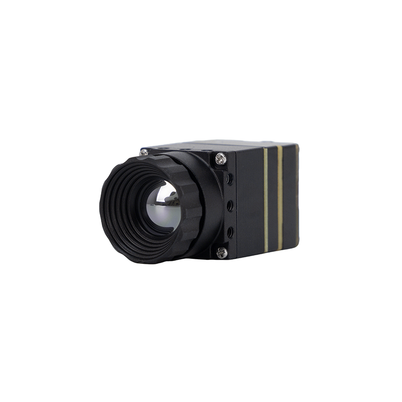
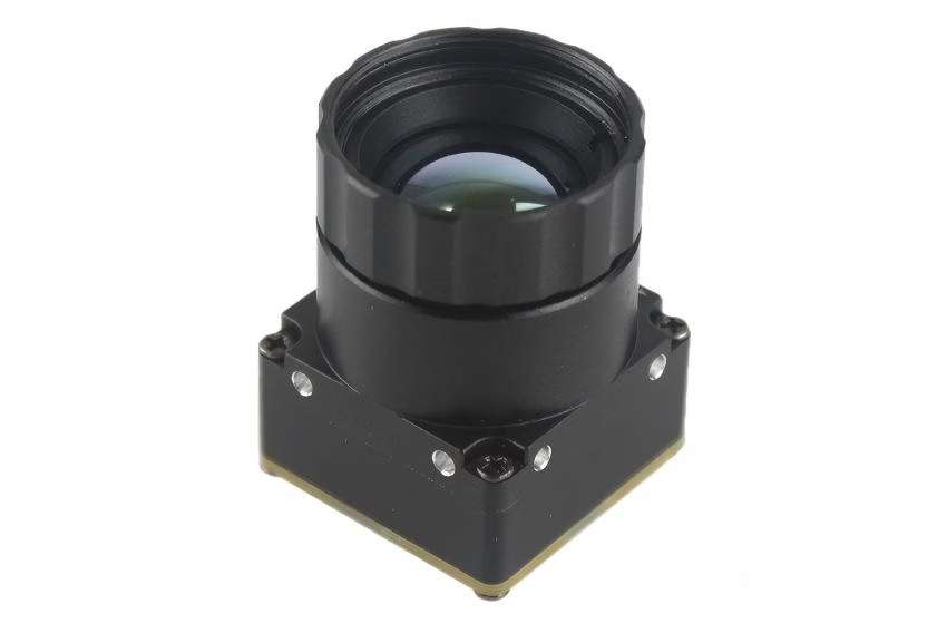
The Purpleriver MD Series thermal camera module is designed for industrial-grade precision in applications such as security, temperature monitoring, and drone integration. Featuring an uncooled infrared detector with a 12μm pixel pitch, it delivers high sensitivity and sharp thermal imaging. Its compact size, plug-and-play functionality, and multiple interfaces (MIPI/USB/CVBS) ensure versatile and rapid integration into various systems. Backed by a team with a Hong Kong University of Science and Technology background and former Huawei Hisilicon expertise, this module offers OEM/ODM customization to meet specific project requirements, ensuring unparalleled performance and adaptability.
Key Specifications & Engineering Details
| Resolution & Pitch: | 384 × 288 Pixels | 12μm Uncooled VOx Bolometer |
| Supported Interfaces: | MIPI-CSI2, USB 2.0 (UVC Compliant), Direct CVBS Analog, UART/I2C Control |
| Target Integration: | Handheld Thermal Radiometers, Predictive Maintenance Tools, Industrial Inspection Drones |
| Customization: | Complete OEM/ODM Customization (Firmware, Optics, Mounts, Custom Algorithms) |
The MD Series serves as an ideal hardware base for next-generation handheld thermal cameras. Because it natively integrates MIPI, USB, and CVBS transceivers on the sensor board, engineering teams can design custom handheld devices without complex interface bridges, significantly lowering system bill-of-materials costs. The core's fast boot times, stable radiometric calibration, and high-efficiency thermal engine make it equally well suited for ruggedized pistol-grip cameras and portable field tablets running real-time diagnostics.
Uncooled MINI 384*288 Thermal Camera Module For Drones
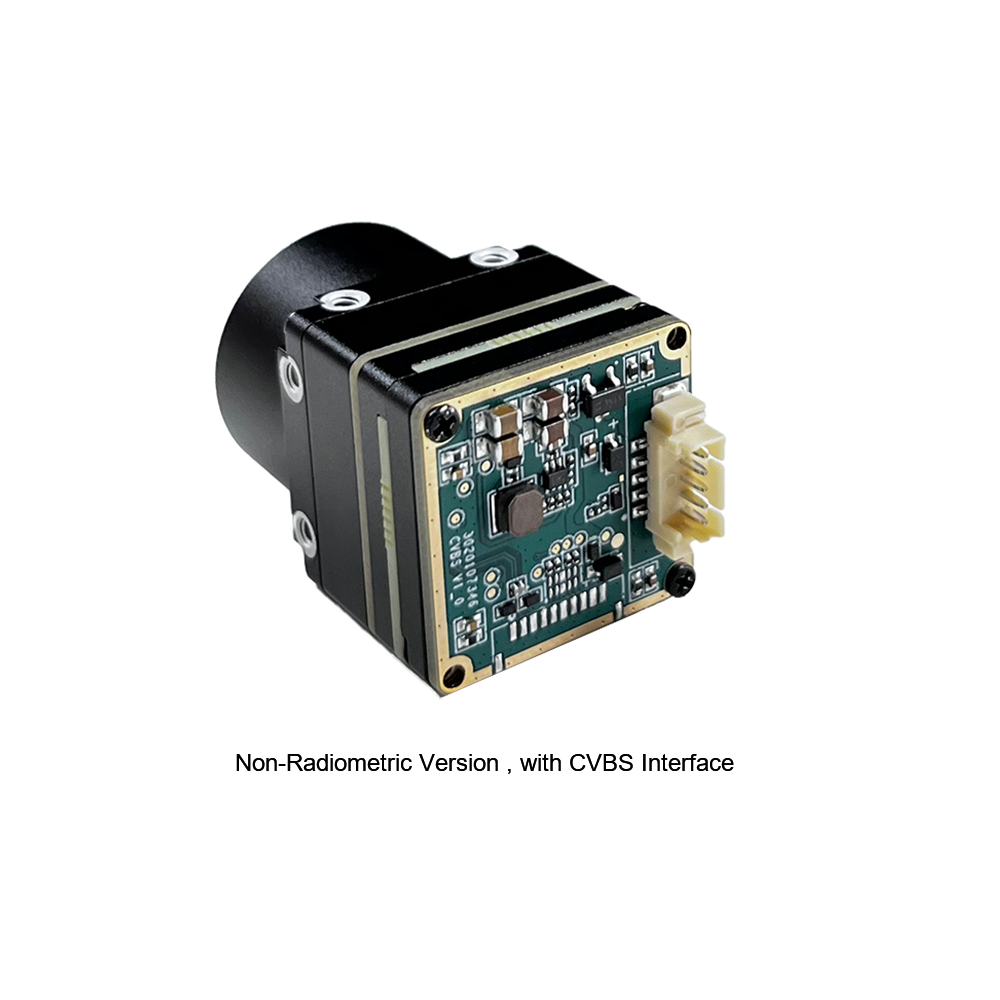
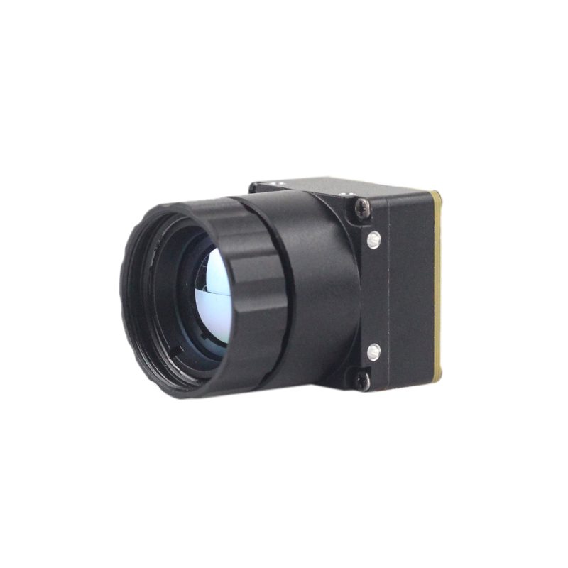
The MINI series infrared thermal imaging temperature measurement module is a high-precision, small-sized, and universal online temperature measurement infrared thermal imager. It uses high-quality detectors, high resolution, stable performance, and powerful functions. It is equipped with multiple interfaces, making it a preferred product in application fields such as machine vision, safety inspection, intelligent manufacturing, equipment maintenance, robot drone airborne, and so on.
Key Specifications & Engineering Details
| Resolution & Pitch: | 384 × 288 Pixels | High-Precision LWIR Focal Plane Array |
| Form Factor & Mass: | Ultra-Compact, Low Weight, High-Efficiency Thermal Footprint |
| Interface Support: | CVBS Analog Output, Multi-Interface Connector Harness, Digital Control |
| Application Scope: | Robotic Mobile Platforms, Airborne Drone Inspection, Machine Vision, Handheld Wands |
The MINI Series focuses on strict Size, Weight, and Power (SWaP) constraints without compromising temperature measurement accuracy. Engineered for weight-sensitive applications such as compact inspection wands, crawlers, and aerial drone gimbals, it includes an integrated thermal engine that delivers continuous temperature data with minimal latency. Its solid structural housing withstands high vibration and mechanical shock profiles, ensuring stable calibration during continuous field operations in demanding manufacturing and flight environments.
6. Selection Matrix: Evaluating Handheld Thermal Imagers for Enterprise Procurement
When purchasing handheld thermal cameras for enterprise diagnostic programs or selecting OEM sensor cores for custom hardware builds, engineering departments must evaluate hardware using rigorous optoelectronic criteria. Prioritizing superficial consumer features over fundamental optical and sensor specifications often results in diagnostic gear that fails to meet field reliability standards.
1. Spatial Resolution & Optical Geometry
Never specify cameras with a resolution below 256×192 pixels for professional industrial predictive maintenance; 384×288 is the recommended baseline standard for facilities with mixed electrical and mechanical assets. Ensure that the sensor resolution paired with the chosen lens configuration achieves an Instantaneous Field of View (IFOV) of 1.3 mrad or lower. This guarantees that small critical components, such as terminal connections and busbar fasteners, can be measured accurately from safe standoff distances.
2. Radiometric Accuracy & Dynamic Temperature Ranges
Industrial condition monitoring generally requires a radiometric baseline accuracy of ±2°C or ±2% of the active reading across standard industrial ranges from -20°C up to +550°C. For specialized environments—such as glass manufacturing, foundries, and industrial kilns—engineers should verify whether the camera includes dual-range or extended calibration profiles reaching +1000°C to +1500°C. These high-temperature profiles require specialized internal optical attenuation to prevent pixel well saturation.
3. Frame Rate Considerations (Hz)
Thermal imagers operating below 9 Hz are exempt from certain international export regulations, but their low frame rate causes severe motion blur during routine inspections. Panning across an electrical panel with a 9 Hz camera results in smeared imagery and can cause technicians to overlook localized hot spots. Handheld cameras intended for dynamic manufacturing floors, high-voltage substations, or mobile mechanical inspections should utilize smooth 25 Hz, 30 Hz, or 50 Hz refresh rates.
4. Ruggedness, Enclosure Ratings & Optical Durability
Field maintenance tools must survive tough operating conditions. Handheld units should feature verified 2-meter drop test certifications and hold an ingress protection rating of at least IP54 (with IP67 preferred for wet or dusty environments). Additionally, the external lens assembly must feature protective Diamond-Like Carbon (DLC) hard-coatings over its front Germanium element to resist scratching, corrosive airborne chemicals, and harsh industrial environments.
5. Enterprise Integration Checklist
Before issuing requests for proposals or standardizing on an enterprise-wide hardware fleet, reliability managers should run candidate models through a practical procurement checklist:
- ✅ Calibration Traceability: Ensure the manufacturer provides factory calibration certificates traceable to national metrology institutes (such as NIST or equivalent ISO/IEC 17025 accredited labs).
- ✅ Radiometric File Export: Verify that saved thermograms are stored as fully radiometric image files (storing 14-bit/16-bit raw temperature matrices per pixel) rather than lossy, flat 8-bit JPEG bitmaps.
- ✅ Interchangeable or Dual-Lens Support: Confirm whether wide-angle and telephoto optical attachments can be swapped in the field without requiring complete factory recalibration.
- ✅ Software and API Ecosystem: Determine if desktop reporting software requires recurring seat subscriptions, and whether an open SDK is available for automating enterprise thermal reporting.
7. Frequently Asked Questions (Technical Deep-Dive)
Is a dedicated handheld thermal camera better than a smartphone plug-in dongle?
Why is a 384x288 resolution sensor considered the sweet spot for handheld thermal inspection?
Can a standard handheld thermal camera measure high temperatures exceeding 1000°F (550°C)?
How do ambient wind speeds and reflected temperature impact field radiometric accuracy?
8. Conclusion and Engineering Summary
Industrial-grade handheld thermography is an indispensable discipline within contemporary predictive maintenance, smart manufacturing, and electrical asset management. Selecting the right imager requires balancing key optoelectronic parameters: matching pixel pitch (12μm) and sensor resolution (384×288) against required stand-off distances to maintain the minimum 3×3 pixel measurement threshold; verifying thermal sensitivity (NETD ≤ 35 mK) for building diagnostics; and securing rugged IP-rated enclosures for harsh field environments.
By integrating proven hardware cores like the Purpleriver MD Series and MINI Series, engineering teams can deploy inspection systems with dependable measurement performance, low power consumption, and flexible interface compatibility (MIPI, USB, CVBS). As factories embrace automated diagnostics and data-driven maintenance, deploying properly calibrated handheld thermal imagers remains the primary defense against unexpected equipment downtime, electrical fires, and catastrophic infrastructure failure.
📚 References & Further Reading
- Industry Standard: Wikipedia Infrared Imaging
- Interconnect Architecture: Micro Coaxial Cable Man
- Related Guide: Next-Gen LWIR Thermal Module Guide: OEM Integration for Drones & AI
- Regional Technical Resource (PL): Komercyjne Rozwiązania Termowizyjne w Podczerwieni (Wysoka Rozdzielczość)
- Regional Technical Resource (AR): دليل اختيار كاميرا حرارية بالذكاء الاصطناعي