







640x512 Arduino-Compatible UART Thermal Camera Module: High-Res Integration Guide
2026年7月23日
Uncooled Infrared MIPI 640 384 256 9mm Thermal Imaging Camera Module for Drones: The Ultimate Customization Guide
2026年7月27日
AMG8833 Thermal Imaging Camera Array Module with USB Power: Is It Ready for Industrial Infrared Temperature Measurement?
Look, the explosion of cheap infrared sensors over the past few years has completely changed how hardware engineers, system integrators, and optics guys look at thermal measurement. Among these budget options, the amg8833 thermal imaging camera array module with usb power for infrared temperature measurement has become a staple on workbench tops, quick-and-dirty prototypes, robotics labs, and basic presence-sensing builds. Built around Panasonic's Grid-Eye MEMS thermopile technology, this little $8 \times 8$ sensor array gives you a 64-pixel thermal footprint. Most module boards pair it with a cheap microcontroller and a USB bridge so you can dump raw thermal frame matrices straight into a PC, a Raspberry Pi, or a Linux edge box. But here is the deal: when you move out of the lab and into industrial automation, drone payloads, or detailed circuit board diagnostics, your requirements change fast. Higher thermal sensitivity, sub-millimeter spatial detail, and dead-accurate radiometric calibration become non-negotiable. System architects have to ask a hard question: can an 8-by-8 thermopile really cut it on the plant floor, or do you need a full-blown uncooled long-wave infrared (LWIR) microbolometer core?
In the industrial world, spatial resolution, optical field of view (FOV), Distance-to-Spot ratio ($D:S$), and thermal noise floor (Noise Equivalent Temperature Difference, or NETD) determine whether you catch an overheating component or miss a critical failure entirely. Sure, an amg8833 thermal imaging camera array module with usb power for infrared temperature measurement offers simple plug-and-play operation for rough hot-spot checks at close range. But its physical limit of just 64 pixels causes massive thermal averaging errors the second you pull back more than a few inches. This guide breaks down the physical architecture of the AMG8833, looks at the real-world thermodynamic issues of running sensors over USB power, cuts through the marketing hype around software interpolation, and points you toward high-resolution thermal cores built for serious B2B applications.
Table of Contents
- 👉 1. Technical Architecture of the AMG8833 Thermal Array Module
- 👉 2. USB Power & Interface Dynamics in Radiometric Infrared Measurement
- 👉 3. Mathematical Interpolation vs. True Optical Microbolometer Resolution
- 👉 4. Industrial Benchmark: 8x8 Thermopiles vs. Professional VOx LWIR Cores
- 👉 5. High-Resolution Industrial Core Specifications & Product Benchmarks
- 👉 6. System Integration Guidelines: UAV, Edge AI, and OEM Automation
- 👉 7. Frequently Asked Questions (FAQ)
1. Technical Architecture of the AMG8833 Thermal Array Module
Under the hood, any amg8833 thermal imaging camera array module with usb power for infrared temperature measurement relies on an 8x8 thermopile array etched onto a micro-electromechanical system (MEMS) die. Quantum photodetectors need cryogenic cooling, and microbolometer focal plane arrays (FPAs) require complex broad-spectrum calibration. Thermopiles take a simpler route: they absorb incoming thermal radiation in the 5 to 13-micrometer band and turn that thermal energy directly into a tiny voltage using series-connected thermoelectric junctions via the Seebeck effect.

The physical structure of the AMG8833 Grid-Eye sensor features 64 distinct thermopile elements laid out in a symmetrical 8-row by 8-column layout. A small silicon lens mounted directly on the package focuses incoming IR light onto the die, giving the package a total field of view (FOV) of $60^\circ$ horizontally by $60^\circ$ vertically. Because that $60^\circ$ FOV gets divided across only 8 elements per axis, each individual pixel sees an angular subtense of roughly $7.5^\circ \times 7.5^\circ$. That is a massive optical footprint for a single pixel to cover.
Key Electro-Optical Parameters
- 📌 Pixel Matrix & Array Size: 64 active detector pixels arranged in a native $8 \times 8$ grid.
- 📌 Optical Field of View (FOV): $60^\circ \times 60^\circ$ overall, yielding a wide $7.5^\circ$ spatial footprint per pixel.
- 📌 Noise Equivalent Temperature Difference (NETD): Rated around $\pm 0.05^\circ\text{C}$ ($0.09^\circ\text{F}$) at a slow $1\text{ Hz}$ frame rate, degrading to roughly $\pm 0.16^\circ\text{C}$ ($0.29^\circ\text{F}$) when pushed to its maximum $10\text{ Hz}$ refresh rate.
- 📌 Absolute Temperature Accuracy: Rated at $\pm 2.5^\circ\text{C}$ ($\pm 4.5^\circ\text{F}$) in high-gain mode under steady room temperature conditions ($25^\circ\text{C}$).
- 📌 Bus Communication & Data Protocols: Uses a native $I^2C$ fast-mode interface ($400\text{ kHz}$) converted to USB CDC (Virtual COM Port) or USB HID through host microcontrollers like the STM32, ATmega32U4, or RP2040.
In basic non-contact thermal physics, as detailed in Wikipedia Thermal Imaging resources, radiated power from an object follows the Stefan-Boltzmann law:
E = ε · σ · T⁴
Where E is radiant emittance, ε is surface emissivity, σ is the Stefan-Boltzmann constant ($5.670374 \times 10^{-8}\,\text{W/m}^2\text{K}^4$), and T is absolute temperature in Kelvin. Because the AMG8833 spreads a $60^\circ$ FOV across just 8 horizontal pixels, every pixel gathers infrared photons over a huge target region. If you place the target 1 meter ($100\text{ cm}$) away, a single pixel covers a square area measuring about $13.1\text{ cm} \times 13.1\text{ cm}$—an area of $171.6\text{ cm}^2$.
In the shop, if a micro-component on a circuit board (say, an 0805 SMD resistor) overheats to $120^\circ\text{C}$ ($393.15\text{ K}$) but occupies only $0.04\text{ cm}^2$ inside that $171.6\text{ cm}^2$ pixel field, the AMG8833 averages that heat across the remaining $171.56\text{ cm}^2$ of cooler $25^\circ\text{C}$ room background. The result? The pixel value barely rises by a fraction of a degree. Your system sees nothing wrong, while the component burns itself out.
2. USB Power & Interface Dynamics in Radiometric Infrared Measurement
Running an AMG8833 module over USB makes life easy on the bench. You plug a single cable into a laptop, PC, or single-board computer, and you get both power supply and serial data output. But if you care about radiometric measurement integrity, running a sensitive analog sensor directly off standard 5V USB power creates real electrical and thermal headaches.
Standard USB power provided by host controllers and cheap hubs is notoriously noisy. Switching regulators, CPU power fluctuations, and dirty ground loops routinely introduce ripple voltage and high-frequency noise anywhere from $20\text{ mV}$ to $150\text{ mV}_\text{p-p}$. The AMG8833 core operates on $3.3\text{V}$ logic, so these modules use low-dropout (LDO) regulators to step down the supply. If those LDOs lack a high Power Supply Rejection Ratio (PSRR) at higher frequencies, power rail noise bleeds straight into the sensor's internal ADC reference circuitry.
When measuring microvolt-level signals from thermopile junctions, unstable reference voltages mean bit jitter. Visually, this turns up as "checkerboarding" across the 64-pixel matrix, baseline temperature drift between consecutive frames, and an active NETD that looks way worse than the datasheet promises.
Thermal Conduction and Sensor Self-Heating
Here is another issue engineers often miss: local thermal conduction on the module PCB. USB-to-UART bridge ICs (like the CP2102, FT232RNL, or CH340) and LDO regulators pull constant current, dumping $50\text{ mW}$ to $200\text{ mW}$ of parasitic heat directly into the circuit board copper.
The AMG8833 relies on an onboard thermistor to handle cold-junction compensation. When parasitic heat from the USB chip creeps through the ground plane, it warms up the sensor housing unevenly. If the internal thermistor reads $33^\circ\text{C}$ due to board heat while room air sits at $22^\circ\text{C}$, the internal compensation math subtracts too much thermal offset. Target readings drop artificially low, ruining your radiometric accuracy right out of the gate.
3. Mathematical Interpolation vs. True Optical Microbolometer Resolution
Because raw $8 \times 8$ thermal grids look blocky and hard to read, almost all host software bundled with an amg8833 thermal imaging camera array module with usb power for infrared temperature measurement runs interpolation math on the incoming data. By using Bilinear, Bicubic, or Thin Plate Spline (TPS) algorithms, host applications blow up that tiny $8 \times 8$ matrix into smooth $320 \times 240$ or $640 \times 480$ color heatmaps.
Smoothing out raw data makes for nice-looking demos, but let us be clear: interpolation adds zero true optical information. It does not boost spatial resolution. It simply computes synthetic color gradient steps between sparse, real data points.
The Mathematics of Thermal Blur and Spatial Undersampling
Take a real-world scenario where two power MOSFETs sit $10\text{ mm}$ apart on a PCB undergoing load testing:
- ⚠️ AMG8833 Array Performance: At a standard bench distance of $30\text{ cm}$, a single AMG8833 pixel covers a square of about $3.93\text{ cm} \times 3.93\text{ cm}$. Both MOSFETs—and the gap between them—fall into the footprint of a single pixel cell. The sensor reads one blended thermal flux value. The software then interpolates this blended value, spreading a soft heat halo across neighboring pixels. The diagnostic software displays a single, broad, blurry hot spot. An engineer cannot tell which component is failing or if a trace is shorted underneath.
- ✅ Uncooled VOx 640x512 Core Performance: A professional LWIR camera module featuring a $12\mu\text{m}$ pixel pitch and a $9\text{mm}$ lens yields 327,680 real optical pixels. At that same $30\text{ cm}$ working distance, each pixel covers an area smaller than $0.4\text{ mm} \times 0.4\text{ mm}$. The camera easily resolves both $10\text{ mm}$ components separately, showing crisp edges, individual junction temperatures, and exact heat spreading across the board traces.
If you are designing custom setups for circuit board inspection, check out our deep-dive on high resolution USB thermal camera module custom OEM cores for PCBA.
4. Industrial Benchmark: 8x8 Thermopiles vs. Professional VOx LWIR Cores
To help you compare component options for your build, the table below highlights the performance gaps between low-cost AMG8833 USB modules and industrial Vanadium Oxide (VOx) uncooled microbolometer camera cores.
| Technical Parameter | AMG8833 USB Module | Standard 256x192 VOx Core | Industrial 640x512 VOx Core |
|---|---|---|---|
| Detector Technology | MEMS Thermopile Array | Uncooled VOx Microbolometer | Uncooled VOx Microbolometer |
| Native Pixel Array | 8 x 8 (64 pixels) | 256 x 192 (49,152 pixels) | 640 x 512 (327,680 pixels) |
| Spectral Response | $5 - 13\,\mu\text{m}$ | $8 - 14\,\mu\text{m}$ (LWIR) | $8 - 14\,\mu\text{m}$ (LWIR) |
| Pixel Pitch | Monolithic IC Silicon Element | $12\,\mu\text{m}$ | $12\,\mu\text{m}$ |
| Thermal Sensitivity (NETD) | $< 50\text{ mK}$ @ $1\text{Hz}$ / $160\text{ mK}$ @ $10\text{Hz}$ | $\le 40\text{ mK}$ ($0.04^\circ\text{C}$) | $\le 30\text{ mK} - 40\text{ mK}$ ($0.03^\circ\text{C}$) |
| Frame Rate | $1\text{ Hz} - 10\text{ Hz}$ | $25\text{ Hz} - 50\text{ Hz}$ | $25\text{ Hz} - 60\text{ Hz}$ |
| Effective Optical Range | $< 0.3\text{ meters}$ | $0.5 - 50\text{ meters}$ | $1 - 500+\text{ meters}$ |
| Hardware Data Output | $I^2C$ / USB Virtual COM (CDC) | USB 2.0 / MIPI CSI-2 / DVP / Network | MIPI CSI-2 / USB 2.0 / LVDS / Analog |
| Radiometric Accuracy | $\pm 2.5^\circ\text{C}$ (Close proximity) | $\pm 2^\circ\text{C}$ or $\pm 2\%$ | $\pm 2^\circ\text{C}$ or $\pm 2\%$ |
| Primary Application Scope | Binary presence, educational kits | Handheld thermal tools, Smart HVAC | UAV payloads, Edge AI, Industrial QA |
As the numbers show, thermopiles like the AMG8833 belong in simple detection setups. For serious manufacturing QA, fast automated lines, and airborne imaging, microbolometers deliver the optical density and speed required. If you are developing handheld systems, take a look at our breakdown on smartphone thermal camera bringing temperature visualization into daily life. For component-level specs and microfabrication standards, engineers often cross-reference data sheets from component vendors like JM Chip.
5. High-Resolution Industrial Core Specifications & Product Benchmarks
When you are building equipment for production lines, drone integration, or edge monitoring, high-performance VOx microbolometer cores offer reliable optical alternatives to simple 8x8 thermopile modules.
Uncooled Infrared MIPI 640/384/256 9mm Thermal Imaging Camera Module For Drones

The Mini2 thermal module offers clear image detail, low power draw, and a tiny physical footprint. Designed specifically for drone gimbals, autonomous platforms, and embedded computer vision units, this camera core relies on uncooled VOx technology to pass raw radiometric video streams across native MIPI CSI-2 interfaces.
| Detector Type: | Uncooled VOx Microbolometer |
| Resolution Options: | 640x512 / 384x288 / 256x192 Native Pixels |
| Pixel Pitch & Optics: | 12μm Pixel Pitch with 9mm Germanium Lens |
| Output Protocol: | Raw MIPI / DVP Video Stream Interface |
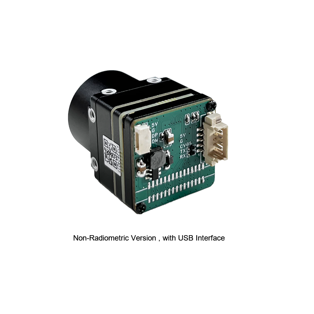
Uncooled LWIR USB Mini 640*512 Thermal Imaging Camera Core Module For Drones
Built into a compact 21mm x 21mm mechanical housing, this LWIR module Streams 640x512 thermal video directly over USB connections. Ideal for industrial IPCs, aerial mapping rigs, and automated station checks, it supports fixed-focus lenses from 5mm up to 150mm.
| Resolution Matrix: | 640x512 Native Uncooled Microbolometer Array |
| Dimensions: | Miniature 21mm × 21mm Housing Form Factor |
| Lens Options: | 5/9/13/18/35/50/75/100/150mm Fixed Focus Optics |
| Connectivity: | Standard USB UVC / Radiometric Temperature Data |
6. System Integration Guidelines: UAV, Edge AI, and OEM Automation
Choosing between low-cost thermopiles and full-resolution microbolometers comes down to math, physical constraints, and data pipeline requirements.
1. Distance-to-Spot Ratio ($D:S$) and Optical Field Calculations
To get a reliable radiometric temperature reading without energy bleeding over the edges, your target must cover a minimum matrix area of at least $3 \times 3$ physical pixels.
When calculated out:
- ⚠️ AMG8833 Limits: With a $7.5^\circ$ per-pixel field, covering a $3 \times 3$ pixel patch on a small $1\text{ cm}^2$ target means placing the sensor closer than $2.5\text{ cm}$ (1 inch). If you pull back to normal working distances ($30\text{ cm}$ to $1\text{ meter}$), the pixel spot size balloons, making spot measurement impossible.
- ✅ 640x512 Core Capabilities: With a $9\text{mm}$ lens ($12\mu\text{m}$ pitch, horizontal FOV $\approx 48^\circ$), each pixel spans just $0.075^\circ$. That same $1\text{ cm}^2$ component easily covers a $3 \times 3$ pixel cluster at inspection distances beyond $2.5\text{ meters}$, which works great on drone mounts or overhead plant installations.
2. Interface Selection: USB Video Class (UVC) vs. MIPI CSI-2
Matching interface options to your host platform saved development headaches down the road:
- 🖥️ USB UVC (USB Video Class): Best for industrial PCs, Windows setups, or Linux boards (Raspberry Pi, NVIDIA Jetson) where standard video drivers save time. Standard USB connections make benchtop setups and laboratory testing quick to build.
- ⚡ MIPI CSI-2 / DVP Interfaces: Essential for light, low-power embedded builds like drone gimbals and mobile robots. Bypassing USB hardware cuts circuit board mass, lowers heat generation, and drops frame latency down to single-digit milliseconds—a big deal for real-time target tracking and Edge AI.
3. Regulatory Compliance and Export Frameworks
When integrating thermal vision hardware running above $9\text{ Hz}$ into export products, keep trade regulations in mind, including ITAR and EAR frameworks. Check our policy details on our terms of use page.
7. Frequently Asked Questions (FAQ)
Why does my AMG8833 thermal module only show clear thermal images within 30cm, and can I calibrate it for long-distance measurement?
The AMG8833 has a native $8 \times 8$ element matrix—giving you just 64 total pixels spread across a wide $60^\circ \times 60^\circ$ optical view. As distance to your target increases, each individual pixel's view grows larger, blending the target's thermal radiation with the surrounding background temperature within the same detector cell.
Beyond $30\text{ cm}$, a target smaller than a couple of inches only takes up a tiny fraction of a single pixel's field, forcing the sensor to report a blended average. While software offsets (tweaking emissivity or manual temperature adjustments) can fix room bias, they cannot bypass fundamental physics and optical sampling limits. Interpolation tricks smooth out visual steps, but they do not add real optical resolution. To measure small targets at a distance, you need an uncooled microbolometer camera core (like a $256 \times 192$ or $640 \times 512$ LWIR module).
Can an AMG8833 USB thermal module reliably handle human presence detection and PCB thermal path checks?
An AMG8833 USB module works fine for basic presence checks in tight, predictable spaces—like detecting if someone is sitting in an office chair or standing right in front of a kiosk within 1 to 2 meters. But it falls flat on PCB thermal path checks, micro-short detection, or precise room tracking.
Inspecting PCBs requires spotting heat anomalies across tiny surface-mount parts (like 0402 or 0603 chips), power management ICs, or trace cracks smaller than a millimeter. The AMG8833's 64 pixels simply lack the spatial resolution to isolate these tiny targets, blending hot spots into adjacent cold traces. For production QA and serious diagnostic work, engineering teams use higher-resolution MIPI or USB LWIR modules that can pinpoint component-level thermal signatures.
How does ambient temperature drift impact USB-powered thermopile modules compared to uncooled VOx cores?
USB-powered thermopile modules suffer from internal board heat. USB bridge chips and voltage regulators draw current and dump heat right into the module's copper traces, creating temperature imbalances across the sensor chip.
Because thermopile sensors compute object temperatures relative to their internal reference thermistor, this board heating messes up compensation math, causing temperature readings to drift over time. Professional uncooled VOx microbolometer cores avoid this by using shuttered or shutterless Non-Uniformity Correction (NUC) algorithms tied to factory calibration tables. These routines adjust individual pixel gains across wide operating ranges ($-40^\circ\text{C}$ to $+80^\circ\text{C}$), keeping measurement drift under control despite USB power noise or ambient temperature shifts.
Is an 8x8 thermopile matrix suitable for high-speed industrial process monitoring on conveyor lines?
No, an 8x8 thermopile matrix is not suitable for fast line monitoring. Aside from severe pixel limitations, the AMG8833 tops out between $1\text{ Hz}$ and $10\text{ Hz}$. Pushing it to $10\text{ Hz}$ degrades its noise performance (NETD) from $0.05^\circ\text{C}$ up to roughly $0.16^\circ\text{C}$, adding visible frame noise.
Industrial lines—like continuous heat sealing, bottling operations, plastic molding inspection, or packaging checks—need high frame rates ($25\text{ Hz}$ to $60\text{ Hz}$) to capture quick thermal events on moving targets. At $10\text{ Hz}$, a part moving down a belt travels inches between frames, creating motion blur and missed defects. High-resolution VOx thermal cores running at $30\text{ Hz} - 60\text{ Hz}$ deliver real-time radiometric streams, allowing automated vision setups to catch rapid heat changes instantly.
📚 References & Further Reading
- Industry Standard Thermal Physics: Wikipedia Thermal Imaging
- Semiconductor Architecture & Fabrication: JM Chip Semiconductor Solutions
- Related Hardware Integration Guide: High Resolution USB Thermal Camera Module Custom OEM Cores for PCBA
- Mobile Thermal Imaging Applications: Smartphone Thermal Camera Bringing Temperature Visualization into Daily Life
- Regulatory Compliance & Terms: Thermal Image System Integration Terms of Use





