








640x512 Thermal Camera Module USB UVC: Premium Plug-and-Play LWIR for UAV & Robotics Integration
2026年7月22日
AMG8833 Thermal Imaging Camera Array Module with USB Power: Is It Ready for Industrial Infrared Temperature Measurement?
2026年7月23日
640x512 Arduino-Compatible UART Thermal Camera Module: High-Res Integration Guide
Plugging high-resolution Long-Wave Infrared (LWIR) sensing into an embedded control setup used to be a complete headache. Back in the day, capturing sharp 640x512 thermal imaging required heavy, power-hungry single-board computers running bloated Linux distros or expensive FPGA framebuffers that ran hotter than the targets you were trying to measure. If you tried hooking a thermal array to a low-power microcontroller, you'd end up with stalled serial buses and out-of-memory errors in minutes.
Look, modern uncooled Vanadium Oxide (VOx) microbolometer cores paired with specialized application-specific integrated circuit (ASIC) processing engines changed the game. Here's the deal: modern hardware offloads the heavy math—radiometric calculations, non-uniformity correction (NUC), spatial filtering, and dynamic range compression—straight onto an onboard ASIC. This leaves your main system free to handle basic control logic without melting down.
By splitting processing into a dual-path architecture, these sensor cores deliver the best of both worlds. While high-speed interfaces like RTSP over Ethernet, CVBS composite video, or MIPI CSI-2 stream live, high-fps thermal motion, low-bandwidth control and telemetry pipelines run quietly over a Universal Asynchronous Receiver-Transmitter (UART) serial connection. This setup lets lightweight microcontrollers like an Arduino, ESP32, or STM32 pull exact temperature matrices, tweak emissivity values, kick off flat-field recalibrations, and read point telemetry using small TTL serial packets—all without running out of SRAM or freezing your control loops.
In the shop, we see engineers make the same handful of wiring and protocol mistakes when setting up thermal camera cores. This technical guide breaks down the underlying physics, hardware wiring strategies, serial telemetry protocols, and C++ driver code you need to reliably field an arduino-compatible uart thermal camera module - 640x512 in industrial edge systems and drone payloads.
Table of Contents
- 👉 1. Architectural Analysis of 640x512 LWIR Microbolometer Sensors
- 👉 2. Interfacing Low-Power Microcontrollers via UART Telemetry
- 👉 3. Hardware Wiring, Power Optimization & Signal Isolation
- 👉 4. Industrial Automation, Edge AI, and UAV Payload Integration
- 👉 5. Industrial Thermal Camera Module Specifications & Comparison
- 👉 6. Implementation Blueprint & Arduino C++ Code Framework
- 👉 7. Deep-Dive Frequently Asked Questions (FAQ)
- 👉 8. Final Engineering Integration Checklist
1. Architectural Analysis of 640x512 LWIR Microbolometer Sensors
Upgrading from low-res sensors (like an 80x60 or 160x120 array) to a 640x512 focal plane array (FPA) completely changes what you can detect in the field. A 640x512 grid gives you exactly 327,680 discrete microbolometer pixels. Compared to a standard 160x120 sensor (which only gives you 19,200 pixels), you are getting a 17-fold jump in spatial pixel density. That extra resolution drastically improves your Distance-to-Spot (D:S) ratio, letting you pull precise temperature readings from hundreds of feet away.
Uncooled thermal sensors work by capturing energy in the Long-Wave Infrared (LWIR) spectrum, which lives between 8μm and 14μm wavelengths. Each pixel inside that 640x512 grid is a tiny, heat-sensitive micro-membrane suspended over a silicon substrate Read-Out Integrated Circuit (ROIC) using ultra-thin support legs. When infrared light hits the Vanadium Oxide (VOx) or Amorphous Silicon (a-Si) film, the material heats up and changes its electrical resistance. The ROIC reads these resistance changes row by row, converting them into raw voltage levels sent off to the onboard ASIC for digitizing and filtering.
When selecting a thermal core for hardware integration, keep a close eye on these physical parameters:
- ⚙️ Pixel Pitch (12μm vs. 17μm): Modern 640x512 cores use a tight 12-micrometer (12μm) pixel pitch. Shrunk-down pixel pitch means the physical physical sensor glass is smaller, allowing you to run shorter, lighter Germanium lens assemblies while keeping the exact same Field of View (FOV). Cutting down glass weight is huge if you are building gimbal payloads for drones or lightweight inspection robotics.
- 🌡️ Noise Equivalent Temperature Difference (NETD): Measured in millikelvins (mK), NETD tells you the smallest temperature delta the sensor can pick up out of background thermal noise. Good industrial-grade cores feature an NETD of ≤40mK (or ≤30mK with an f/1.0 lens), meaning the system can routinely resolve temperature swings down to 0.03°C.
- 📐 Instantaneous Field of View (IFOV): IFOV defines the physical spatial area a single pixel sees, calculated as $IFOV = d / f$, where $d$ is the pixel pitch (12μm) and $f$ is the lens focal length. A 640x512 array gives you a much tighter IFOV than smaller sensors running identical glass, letting you spot small targets like hot electrical splices or motor bearings from far away.
- 🔬 Precision Optical Assemblies: Directing clean LWIR light across a wide 640x512 grid requires specialized glass tuned for infrared pass-through. Lenses built by optics suppliers like LightPath Technologies use anti-reflective coated Germanium or chalcogenide glass to cut down spherical aberrations and preserve uniform thermal accuracy across every corner of the image.
2. Interfacing Low-Power Microcontrollers via UART Telemetry
When hooking up a 640x512 thermal core to a microcontroller, you need to carefully account for processor clock speed, bus bandwidth, and onboard SRAM. Ignoring memory bottlenecks is the fastest way to wind up with corrupted serial buffers and locked-up microcontrollers.
Let's run the actual math on trying to push full, uncompressed thermal frames into memory. Standard radiometric thermal sensors output pixel values as 16-bit unsigned integers representing raw thermal ADC steps. The RAM required to buffer just one uncompressed 640x512 thermal frame looks like this:
$$\text{Frame Buffer Size} = 640 \times 512 \times 2 \text{ bytes} = 655,360 \text{ bytes } (\approx 640 \text{ KB})$$
A classic 8-bit Arduino Uno (ATmega328P) has just 2 KB of total SRAM and runs at 16 MHz. An 8-bit Arduino Mega 2560 gives you 8 KB of SRAM. Even capable 32-bit chips like the ESP32 (with 520 KB of internal SRAM) or SAMD21 (32 KB SRAM) cannot fit a single 640 KB raw frame into contiguous memory without external PSRAM ICs. Plus, pushing 640 KB of raw pixel values at 30 frames per second across a standard serial pin would require a baud rate well over 156 Megabits per second (Mbps)—far beyond what physical TTL hardware UART pins can handle.
The solution is an architecture that lets the camera's onboard ASIC do the heavy lifting. The ASIC handles image capture, non-uniformity correction, noise reduction, color palette rendering, and temperature scaling right on dedicated video hardware. It pumps out clean high-definition analog composite video (CVBS) or digital IP streams (RTSP) over dedicated video interfaces directly to displays or edge AI processors.
At the same time, the core opens up a low-power UART command and telemetry port. Instead of asking your microcontroller to process 640 KB frame arrays, the camera's internal ASIC parses the scene and sends lightweight serial packets (usually 16 to 64 bytes) down to your Arduino. These packets give you actionable data without bogging down your control loop:
- 📌 Global Radiometric Spot Temps: Real-time float values for max target temp, min target temp, and center-spot scene temperature.
- 🎯 Hotspot Pixel Coordinates: Exact $X, Y$ coordinate vectors mapping the location of the highest heat anomaly in the 640x512 frame.
- 🎨 Dynamic Palette Toggling: Serial commands to flip the video output between Ironbow, White Hot, Black Hot, Rainbow, and Isotherm color spaces on the fly.
- 🔄 Flat-Field Correction (FFC) Controls: Triggers to fire internal mechanical shutters or software NUC routines to keep thermal readings accurate when ambient temperatures shift.
If you want a deeper look into the sensor integration side, check out our engineering write-up on high-precision thermal module integration.
3. Hardware Wiring, Power Optimization & Signal Isolation
Wiring up a 640x512 thermal module in an industrial environment takes clean electrical design. Uncooled microbolometers are notoriously sensitive to power rail ripple and electromagnetic noise. Dirty power supplies will cause annoying horizontal lines to crawl across your thermal output.
Most industrial 640x512 thermal modules break out connections using fine-pitch Hirose or Molex ribbon connectors. Here is a standard hardware pinout and wiring setup for an industrial UART/Video thermal core:
| Pin Number | Signal Name | Electrical Specification | Recommended Connection |
|---|---|---|---|
| Pin 1 | VCC (+5V DC) | 5.0V DC ±0.2V (Peak 1.5A during FFC shutter) | Regulated Low-Noise LDO Power Supply |
| Pin 2 | GND | 0V Logic Ground Return | System Common Ground Plane |
| Pin 3 | UART_TX | 3.3V TTL Logic (Transmit Output from Camera) | Arduino RX Pin (via 3.3V/5V Level Shifter if using 5V MCU) |
| Pin 4 | UART_RX | 3.3V TTL Logic (Receive Input to Camera) | Arduino TX Pin (via 3.3V/5V Level Shifter if using 5V MCU) |
| Pin 5 | CVBS+ | 1.0V p-p Composite Analog Video (75Ω) | Analog Video Monitor / FPV Transmitter Core |
| Pin 6 | CVBS- / Shield | Analog Ground / Coaxial Shield | Display Analog Ground Return |
| Pin 7-8 | ETH_TX / RX | Differential Pair (RTSP / IP Video Stream) | RJ45 Magnetic Jack / Ethernet Switch Core |
When laying out power traces and logic runs on custom carrier boards, keep these hardware rules in mind:
- ⚡ Bi-Directional Logic Level Shifting: Standard 8-bit Arduinos (like the Mega 2560 or Uno) run 5.0V TTL logic. Modern thermal camera ASICs use 3.3V CMOS logic on their UART lines. Hooking a 5V TX line directly into a 3.3V camera RX pin will fry the ASIC input stage over time. Always put an active level shifter (like a MOSFET-based BSS138 converter) between your serial pins.
- 🔋 Power Supply Ripple Suppression: Thermal FPAs need ultra-clean power. Running camera cores directly off noisy DC-DC buck converters or motor power rails introduces spatial image noise. Power your thermal core through an independent Low-Dropout (LDO) linear regulator, and place a $100\mu\text{F}$ tantalum capacitor alongside a $0.1\mu\text{F}$ ceramic capacitor right next to the camera power connector.
- 🔌 Ground Plane Isolation: Keep power ground, digital UART signal ground, and high-frequency analog video ground separated on your PCB. Tie them together at a single star-ground point near the primary power terminal to prevent ground loops from ruining your analog video signal.
4. Industrial Automation, Edge AI, and UAV Payload Integration
Pairing 640x512 thermal vision with an Arduino-level UART telemetry line opens up reliable system designs across drones, robotics, and factory monitoring.
On airborne drone payloads, keeping weight low and power efficiency high directly impacts overall flight time. Mounting a high-res thermal sensor onto an airframe lets operators run roof scans, solar farm inspections, and power line checks from safe flight distances. An onboard microcontroller reads flight telemetry over MAVLink while continuously checking thermal readings over UART. When target temperatures cross safety limits ($>85^\circ\text{C}$), the microcontroller logs GPS vectors, flips the camera shutter, and broadcasts immediate alert tags to ground crews over telemetry radios. If you are building custom airframes and gimbal assemblies, platforms manufactured by drone builders like OBSETECH offer ruggedized airframes tuned for dual-sensor payloads.
In factory edge automation, dual-processor setups separate heavy visual AI from low-latency safety interlocks. An edge AI board (such as an NVIDIA Jetson Orin Nano or Raspberry Pi 5) ingests high-res RTSP video over Ethernet to run vision models like YOLOv8 for object detection. At the same time, an isolated micro-controller queries the camera over UART. Even if the main AI platform drops frames or suffers software glitches, the dedicated hardware microcontroller keeps reading target temperatures, guaranteeing immediate mechanical relay shutoff if industrial equipment overheats.
For operations needing visual optical context alongside infrared detection, dual-light camera cores—such as our 256 dual thermal and visual sensor module—offer visible light and thermal channels in one compact enclosure.
5. Industrial Thermal Camera Module Specifications & Comparison
Selecting the right thermal camera module for an embedded build comes down to evaluating resolution, pixel pitch, interface options, package mass, and telemetry support. Below are technical breakdowns of two featured industrial thermal camera modules.
Product 1: Uncooled Infrared RJ45 CVBS RTSP IP 640*512 Thermal Sensor Camera Module

Built for industrial security, long-range defense systems, and drone integrations, this thermal camera core is built around a 640x512 VOx microbolometer array backed by an onboard ASIC processing engine. It delivers versatile interface options, outputting IP video over RJ45 Ethernet (RTSP), low-latency composite analog video (CVBS) for direct display feeds, and a lightweight TTL UART control interface for real-time telemetry extraction using Arduino or ESP32 hardware. Its compact footprint and low power draw make it ideal for weight-restricted aerial payloads.
| Resolution | 640 x 512 Pixels |
| Detector Type | Uncooled VOx Microbolometer Array |
| Pixel Pitch | 12μm |
| Interfaces | RJ45 Ethernet (RTSP/IP), CVBS Analog Composite, UART Serial |
| Primary Application | UAV Payloads, Long-Range Surveillance, Industrial Security |
View Product Details & Pricing ➔
Product 2: MD Series 384x288 Uncooled Infrared Thermal Camera Module
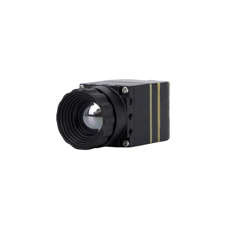
The Purpleriver MD Series module brings high thermal precision to localized monitoring, handheld robotics, and embedded equipment inspection. Packing a 12μm uncooled infrared array, it delivers clear thermal frames in a light, micro-sized package. Designed by an engineering team with roots at the Hong Kong University of Science and Technology (HKUST) and former Huawei HiSilicon R&D groups, the MD series supports plug-and-play connections across MIPI, USB, CVBS, and UART outputs. Full OEM customization options let development teams modify lens mounts, connector pinouts, and custom communication protocols for specific system designs.
| Resolution | 384 x 288 Pixels |
| Detector Type | Uncooled Infrared Sensor (12μm Pitch) |
| Interfaces | MIPI, USB, CVBS Composite, UART Telemetry |
| Engineering Team | HKUST Academic & Former Huawei HiSilicon R&D Team |
| Primary Application | Industrial Predictive Maintenance, OEM System Integration, Robotics |
View Product Details & Pricing ➔
Technical Specification Comparison
| Specification Parameter | 640x512 ASIC IP/CVBS Module | MD Series 384x288 Module |
|---|---|---|
| Focal Plane Resolution | 640 x 512 (327,680 Pixels) | 384 x 288 (110,592 Pixels) |
| Pixel Pitch | 12μm | 12μm |
| Spectral Range | 8μm to 14μm (LWIR) | 8μm to 14μm (LWIR) |
| Digital/Video Interfaces | RJ45 Ethernet (RTSP/IP), CVBS | MIPI, USB 2.0, CVBS |
| Control & Telemetry | UART TTL Serial Protocol | UART TTL Serial Protocol |
| Form Factor Target | Medium-to-Long Range Aerial Payloads | Compact OEM Robotics & Maintenance Systems |
| Customization Services | Hardware & Software OEM/ODM | Hardware & Software OEM/ODM |
For custom engineering inquiries, head directly to our secure OEM order page.
6. Implementation Blueprint & Arduino C++ Code Framework
The practical C++ implementation below shows how an arduino-compatible uart thermal camera module - 640x512 talks to an Arduino host (such as an Arduino Mega 2560 or ESP32 using a dedicated hardware serial port Serial1). The code periodically queries the camera core, decodes returning serial bytes, pulls maximum scene temperatures alongside their exact $X, Y$ pixel coordinates, and monitors temperature alarm thresholds.
/*
 * Industrial High-Resolution 640x512 Thermal Camera UART Driver
 * Architecture: Non-blocking hexadecimal protocol parser
 * Target MCUs: Arduino Mega 2560, ESP32, STM32 (3.3V Logic on Serial1)
 */

#include <Arduino.h>

// Protocol framing definitions for camera ASIC interface
const uint8_t FRAME_HEADER_1 = 0x55;
const uint8_t FRAME_HEADER_2 = 0xAA;
const uint8_t CMD_GET_SPOT_METRICS = 0x81;
const uint8_t FRAME_FOOTER   = 0x0D;

struct ThermalTelemetry {
  float maxTemperature;
  float minTemperature;
  uint16_t maxPixelX;
  uint16_t maxPixelY;
  bool packetValid;
};

// Function Declarations
void sendTelemetryQuery();
ThermalTelemetry processIncomingSerialData();

void setup() {
  // Initialize USB Serial Debug Line to Host PC
  Serial.begin(115200);
  while (!Serial) { ; } // Wait for terminal connection

  // Initialize Hardware UART interface connected to Thermal Module
  // NOTE: Verify bi-directional logic level shifter is present if using 5V MCU!
  Serial1.begin(115200);

  Serial.println(F("[SYSTEM OK] Thermal Camera Telemetry Interface Online."));
  delay(1000);
}

void loop() {
  static unsigned long lastQueryTimestamp = 0;
  const unsigned long queryIntervalMs = 250; // Query rate: 4 Hz

  // Execute non-blocking timer query
  if (millis() - lastQueryTimestamp >= queryIntervalMs) {
    lastQueryTimestamp = millis();
    sendTelemetryQuery();
  }

  // Parse incoming serial data from camera module
  if (Serial1.available() >= 12) {
    ThermalTelemetry metrics = processIncomingSerialData();

    if (metrics.packetValid) {
      Serial.print(F("[RADIOMETRY] Max Temp: "));
      Serial.print(metrics.maxTemperature, 2);
      Serial.print(F(" °C at Pixel Vector X: "));
      Serial.print(metrics.maxPixelX);
      Serial.print(F(" | Y: "));
      Serial.println(metrics.maxPixelY);

      // System Alarm Condition
      if (metrics.maxTemperature > 80.0f) {
        Serial.println(F("[ALARM WARNING] Thermal Safety Threshold Exceeded!"));
        // Digital relay actuation commands can be triggered here
      }
    }
  }
}

void sendTelemetryQuery() {
  // Construct 6-Byte Serial Frame: [HEADER1, HEADER2, LENGTH, CMD, CHECKSUM, FOOTER]
  uint8_t packet[6];
  packet[0] = FRAME_HEADER_1;
  packet[1] = FRAME_HEADER_2;
  packet[2] = 0x02; // Payload Byte Count
  packet[3] = CMD_GET_SPOT_METRICS;
  packet[4] = (uint8_t)(FRAME_HEADER_1 ^ CMD_GET_SPOT_METRICS); // XOR Checksum
  packet[5] = FRAME_FOOTER;

  Serial1.write(packet, 6);
}

ThermalTelemetry processIncomingSerialData() {
  ThermalTelemetry data = {0.0f, 0.0f, 0, 0, false};

  // Scan serial buffer for matching double-header frame alignment
  if (Serial1.read() == FRAME_HEADER_1) {
    if (Serial1.read() == FRAME_HEADER_2) {
      uint8_t length = Serial1.read();
      uint8_t command = Serial1.read();

      if (command == CMD_GET_SPOT_METRICS) {
        // Read raw data bytes from camera ASIC
        uint8_t rawMaxHigh = Serial1.read();
        uint8_t rawMaxLow  = Serial1.read();
        uint8_t xCoordHigh = Serial1.read();
        uint8_t xCoordLow  = Serial1.read();
        uint8_t yCoordHigh = Serial1.read();
        uint8_t yCoordLow  = Serial1.read();
        uint8_t checksum   = Serial1.read();
        uint8_t footer     = Serial1.read();

        if (footer == FRAME_FOOTER) {
          // Reconstruct raw 16-bit signed integer and scale to Celsius
          int16_t rawSignedTemp = (int16_t)((rawMaxHigh << 8) | rawMaxLow);
          data.maxTemperature = rawSignedTemp / 10.0f; // Scale factor: 0.1°C per LSB

          data.maxPixelX = (uint16_t)((xCoordHigh << 8) | xCoordLow);
          data.maxPixelY = (uint16_t)((yCoordHigh << 8) | yCoordLow);

          data.packetValid = true;
        }
      }
    }
  }
  return data;
}

7. Deep-Dive Frequently Asked Questions (FAQ)
Can an 8-bit Arduino process full 640x512 thermal video frames directly?
The key to making low-power microcontrollers work with 640x512 thermal modules is leaning on the camera's onboard ASIC. The ASIC handles non-uniformity correction (NUC), image processing, and temperature math right on the camera, outputting visual video over hardware channels (like RTSP Ethernet or CVBS analog). At the same time, the camera sends compact telemetry bytes (16 to 32 bytes) over UART to your Arduino. This architecture lets your microcontroller track target hot-spots, trigger alerts, and run control logic without touching a video buffer.
Why is bi-directional logic level shifting critical when connecting an Arduino to a camera UART interface?
Even on the receiving side, while a 3.3V signal from the camera might trigger a high logic level on a 5V MCU, signal noise in industrial environments will lead to dropped serial packets and framing errors. Installing an active bi-directional level shifter (like a BSS138 MOSFET driver) cleanly maps signals between 5.0V and 3.3V, keeping your hardware safe and your serial bus stable.
How do ambient temperature shifts affect microbolometer calibration, and how is it managed over UART?
To keep readings accurate, thermal camera modules perform Flat-Field Correction (FFC), also known as Non-Uniformity Correction (NUC). During an FFC cycle, an internal shutter drops in front of the sensor (or a digital algorithm runs) to give the array a uniform thermal baseline. The camera ASIC recalculates gain and offset parameters for every pixel in the 640x512 matrix. You can send serial commands over UART from your Arduino to trigger FFC cycles whenever ambient conditions swing.
8. Final Engineering Integration Checklist
Before deploying your thermal camera setup in the field, double-check your build against this integration checklist:
- ✅ Voltage Logic Compliance: Active bi-directional logic level shifters installed between 5.0V microcontroller serial pins and 3.3V camera ASIC I/O lines.
- ✅ Regulated Power Supply: Dedicated 5V Low-Dropout regulator rated for at least 2.0A peak current to handle transient surges during mechanical shutter fires.
- ✅ Filtering Capacitors: Decoupling capacitor pair ($100\mu\text{F}$ tantalum + $0.1\mu\text{F}$ ceramic) soldered right next to the camera power connector pins.
- ✅ Common Grounding: Single-point ground path set up across power supply, microcontroller, level shifters, and external video display boards.
- ✅ Non-Blocking Code Structure: Embedded code relies on timer offsets (`millis()`) and frame headers to parse serial bytes without halting safety control loops.
- ✅ Lens Selection: Anti-reflective Germanium or Chalcogenide glass selected to match your target Field-of-View (FOV) and operating distance requirements.
📚 References & Further Reading
- Optical Engineering: LightPath Technologies Precision Thermal Optics Solutions
- UAV Hardware Platforms: OBSETECH Tactical Drone & Gimbal Hardware Systems
- Technical Integration Guide: High Precision Thermal Module Integration Best Practices
- Dual Thermal & Visual Product: 256 Dual Thermal and Visual Sensor Camera Core
- Procurement & Custom Ordering: Thermal Sensor Engineering Procurement Portal





