Best Micro Thermal Camera Module Guide: High-Res Integration for Drones, Raspberry Pi & Edge AI
2026年6月10日
Thermal Camera Sensor Module Guide: High-Res OEM Cores for Drones & SBCs
2026年6月11日
Best Raspberry Pi Thermal Camera Module for High-Res Edge AI & Linux Streaming
In the field, when you're building systems for industrial automation, drone surveillance, or edge AI detection, you can't afford to guess. You need real, hard, actionable spatial and thermal data. For years, folks in the shop tried to scrape by using basic temperature sensors and cheap thermopile arrays for simple proximity sensing and DIY bench projects. But let's be honest: those setups completely fall apart when you throw them into mission-critical environments like high-speed pipeline monitoring, commercial security, or autonomous drone navigation. If you want to build a system that actually works under real-world conditions, the standard is clear: you need an industrial-grade uncooled Long-Wave Infrared (LWIR) thermal camera module paired with a rugged, versatile single-board computer like the Raspberry Pi 4 or Raspberry Pi 5.
Selecting the right raspberry pi thermal camera module isn't just about grabbing the cheapest sensor with a high pixel count off a shelf. You have to balance raw resolution, interface overhead, and processing power. If you try to push high-resolution data (like a 640×512 array) through a slow, outdated micro-bus, your frame rate will crawl and your CPU will spike. Using high-bandwidth pipelines like USB (UVC) or RJ45 (RTSP over Ethernet) is how you bypass those massive processing bottlenecks. This guide is a complete blueprint from our engineering bench to yours, showing you exactly how to configure professional-grade uncooled LWIR sensor cores with Linux-based Raspberry Pi systems, optimize your edge AI pipelines, and stream crystal-clear, low-latency thermal feeds.
Table of Contents
- 👉 1. The Bottlenecks of Low-Resolution DIY Sensors vs. Industrial LWIR Cores
- 👉 2. Architecture of Modern LWIR Sensors: Microbolometers, ASIC, and Lenses
- 👉 3. Raspberry Pi Integration Protocols: USB/UVC vs. RJ45/RTSP/IP Cores
- 👉 4. Industrial Raspberry Pi Thermal Modules: Real Specifications & Comparison
- 👉 5. Building an Edge AI & Linux Streaming Pipeline on Raspberry Pi
- 👉 6. Deep-Dive B2B Technical FAQ
1. The Bottlenecks of Low-Resolution DIY Sensors vs. Industrial LWIR Cores
When teams are just starting to sketch out a concept on the bench, it’s incredibly tempting to buy cheap. You see entry-level thermopile arrays like the MLX90640 (32×24 pixels) or the AMG8833 (8×8 pixels) and think, "Hey, this is cheap, let's just use this to prove the concept." But here's the deal: those cheap chips are basically glorified thermometers. They work fine for simple tasks like seeing if a human is standing right in front of a smart kiosk, but they completely fail when you need to track targets, run automated industrial inspections, or fly a thermal camera on a drone.
The Spatial Resolution Gap
Look at the math. A standard 640×512 Focal Plane Array (FPA) gives you exactly 327,680 individual thermal pixels. An MLX90640 gives you a measly 768 pixels. That is a massive 426-fold increase in spatial resolution. If you are trying to capture a heat source from 50 yards away with an 8×8 or 32×24 array, that target is going to occupy exactly one or two blurry pixels. You won't be able to tell if you're looking at a human, a pump motor that's about to overheat, or just hot asphalt reflecting the sun. The image is a pixelated mess.
An industrial uncooled LWIR core with a 640×512 resolution preserves fine, high-frequency details. This structural definition is what makes it possible for neural networks, edge detection models, and human operators to reliably identify shapes, read thermal gradients, and track long-range targets. If you are interested in seeing how engineers scale these setups, you can check out Can we convert a regular camera into a thermal imaging camera? or dive deep into the fundamental physics in thermal imaging sees the world: the infrared secrets you don't know.

Bandwidth & Interface Limitations
Cheap, low-resolution sensors usually talk to your board over I2C or SPI. If you try to overclock an I2C bus to its Fast Mode Plus limits (1 Mbps), you still run into high transactional overhead and zero support for Direct Memory Access (DMA). Now do the math for an industrial-grade stream: a 640×512 sensor running 14-bit raw radiometric data (packed into 16-bit structures) means a single frame is 655,360 bytes of data. At a standard framerate of 25Hz or 30Hz, you are looking at a sustained bandwidth of roughly 15.7 MB/s (or 131 Mbps).
If you try to shove that massive amount of raw data through a standard Raspberry Pi SPI or I2C bus, you will choke the system. You will saturate the bus, spike your CPU to 100%, and drop frames left and right. This bandwidth bottleneck makes it impossible to run fluid thermal video while trying to do actual edge processing on the same board. To solve this, modern industrial cores use an on-board ASIC or System-on-Chip (SoC) to do the heavy lifting of sensor calibration, bad pixel correction, and non-uniformity correction (NUC) right on the sensor. The processed video is then delivered over clean, fast, high-speed interfaces:
- ✅ USB Video Class (UVC): This lets your camera stream uncompressed frames directly over USB 2.0 or 3.0. This uses standard system-level DMA engine drivers to write stream data directly to RAM, meaning your CPU barely feels a thing.
- ✅ RJ45 (RTSP over IP): The sensor module compresses the thermal video directly on-board using H.264 or H.265 compression, packages it, and streams it over a reliable network interface. The Raspberry Pi can decode this stream using its built-in hardware VPUs, leaving your CPU entirely free to run your machine learning models and edge logic.
2. Architecture of Modern LWIR Sensors: Microbolometers, ASIC, and Lenses
An industrial uncooled LWIR sensor is a highly complex piece of optoelectronic equipment designed to operate flawlessly under brutal field conditions. To integrate these arrays into commercial products, you need to understand exactly what is happening inside the focal plane array, the processing ASIC, and the optical assemblies.
Uncooled VOx Microbolometer Dynamics
The beating heart of an industrial thermal sensor is an array of uncooled Vanadium Oxide (VOx) microbolometers. Cooled thermal cameras require heavy, expensive, and fragile cryocoolers that pull a ton of power. Uncooled VOx microbolometers, on the other hand, measure the temperature-dependent electrical resistance changes in each individual pixel as incident infrared radiation strikes them.
- ⚙️ Pixel Pitch (12μm vs. 17μm): Modern arrays use a tight 12μm pixel pitch instead of the older 17μm standard. Decreasing the pixel pitch means you can pack more resolution onto a smaller sensor footprint, allowing you to use lighter, more compact optical setups without sacrifice.
- ⚙️ Thermal Sensitivity (NETD): Rated in millikelvins (mK), Noise Equivalent Temperature Difference is the spec that tells you how sensitive your sensor is. An NETD of 40mK or 50mK means the sensor can resolve temperature differences as tiny as 0.04°C or 0.05°C. This is the difference between seeing a clear, detailed heat map of a circuit board and looking at a pile of grainy noise.
The Role of Custom ASIC Cores
In the shop, we know that raw uncooled microbolometer data is incredibly messy. Because microbolometers are highly susceptible to local thermal drift, environmental conditions, and semiconductor variations, the raw output has to be heavily processed before it is usable. A high-end thermal core features a dedicated ASIC on-board that handles these intensive corrections in real time:
- ⚙️ Non-Uniformity Correction (NUC): Normalizes the gain and offset variation across all 320,000+ pixels.
- ⚙️ Bad Pixel Replacement (BPR): Constantly monitors and maps dead or locking pixels, interpolating their values using processing algorithms from neighboring pixels.
- ⚙️ Digital Detail Enhancement (DDE): Applies high-pass spatial filtering to pull out low-contrast features, like thin wires or far-away objects, from a scene with a very wide temperature dynamic range.
- ⚙️ Automatic Gain Control (AGC): Uses advanced histogram equalization (like CLAHE) to scale the dynamic thermal range, ensuring you don't lose human targets or hot spots when the ambient temperature shifts.
Precision Infrared Optics
You can't use standard optical glass for a thermal camera; glass completely blocks waves in the long-wave infrared spectrum (8μm to 14μm). That means we have to use highly specialized IR-transmitting materials:
- ⚙️ Germanium (Ge): The classic choice for high-end thermal systems. It has outstanding transmission and a high refractive index, but it is heavy and incredibly expensive to source and machine.
- ⚙️ Chalcogenide Glass: This is a newer, high-performance optical material composed of selenium, sulfur, or tellurium compounds. It offers excellent transmissive properties and great thermal stability, all while keeping weight and production costs way down. This material is key for keeping drone payloads lightweight. You can find modules utilizing these advanced optical materials from innovative suppliers like Shenzhen ChiYi Electronics Co., Ltd. or source custom optical assemblies directly from aerospace-grade suppliers like LightPath Technologies.
3. Raspberry Pi Integration Protocols: USB/UVC vs. RJ45/RTSP/IP Cores
How you wire your thermal core to the Raspberry Pi changes everything. It dictates your pipeline latency, your CPU overhead, and the physical limits of your setup.
Protocol Comparison: UVC vs. RTSP
UVC (USB Video Class)
USB-integrated modules behave like standard, plug-and-play USB web cams. Raspberry Pi's Linux kernel handles this natively through the robust Video4Linux2 (V4L2) subsystem.
- ✅ Zero-Configuration Pipeline: It is incredibly easy to get running. Plug it in, open an OpenCV capture slot on
/dev/video0, and you are pulling frames. - ✅ Ultra-Low Latency: Because you aren't compressing, packetizing, or encoding the data, point-to-point latency is typically well under 50ms.
- ✅ Efficient Local Processing: Frame transfers use system DMA to pull the stream directly into your Python or C++ application RAM without chewing up CPU cycles. This is the gold standard for real-time edge processing on a single, local board.
RTSP (Real-Time Streaming Protocol)
IP-enabled systems host their own internal network stack, web interface, and hardware-accelerated compression chips.
- ✅ Long-Distance Cabling: Unlike USB which fails past 15 feet without expensive active extenders, Ethernet runs up to 328 feet over standard Cat5e or Cat6 cables.
- ✅ Multi-Client Distribution: The camera compresses the stream on-board and serves it over RTSP. That means multiple devices on your network can view the thermal feed simultaneously.
- ✅ Low System Burden: The Raspberry Pi doesn't have to compress the video. It just captures the network stream and can use its hardware accelerated decoders (like
v4l2m2m) to decode it smoothly, preserving CPU time for your deep learning applications.
4. Industrial Raspberry Pi Thermal Modules: Real Specifications & Comparison
When selecting a professional, uncooled 640×512 thermal core for a Raspberry Pi project, your choice will typically land on either a network-ready IP module or an ultra-compact USB module. Let's look at two industry-standard configurations that are built for reliable integration on Linux platforms.
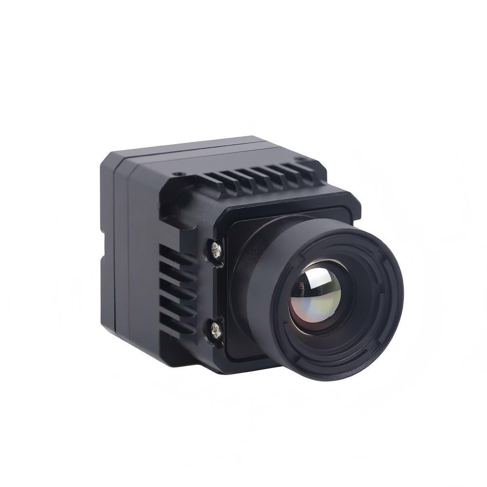
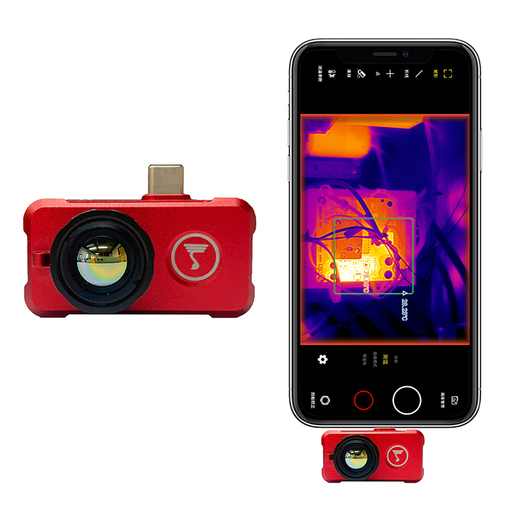
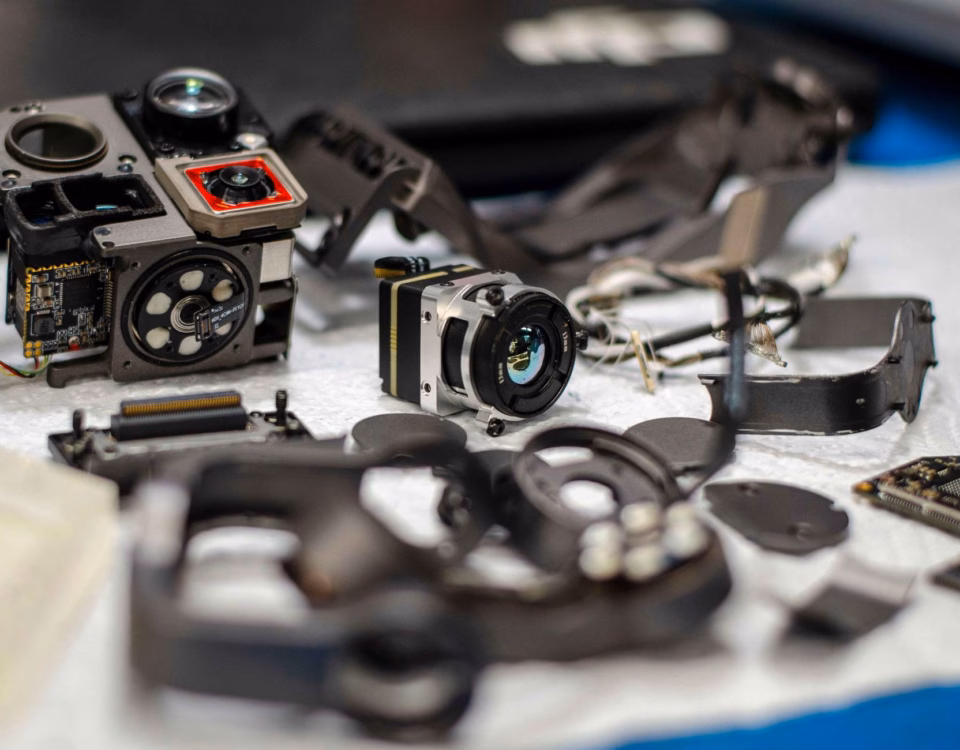
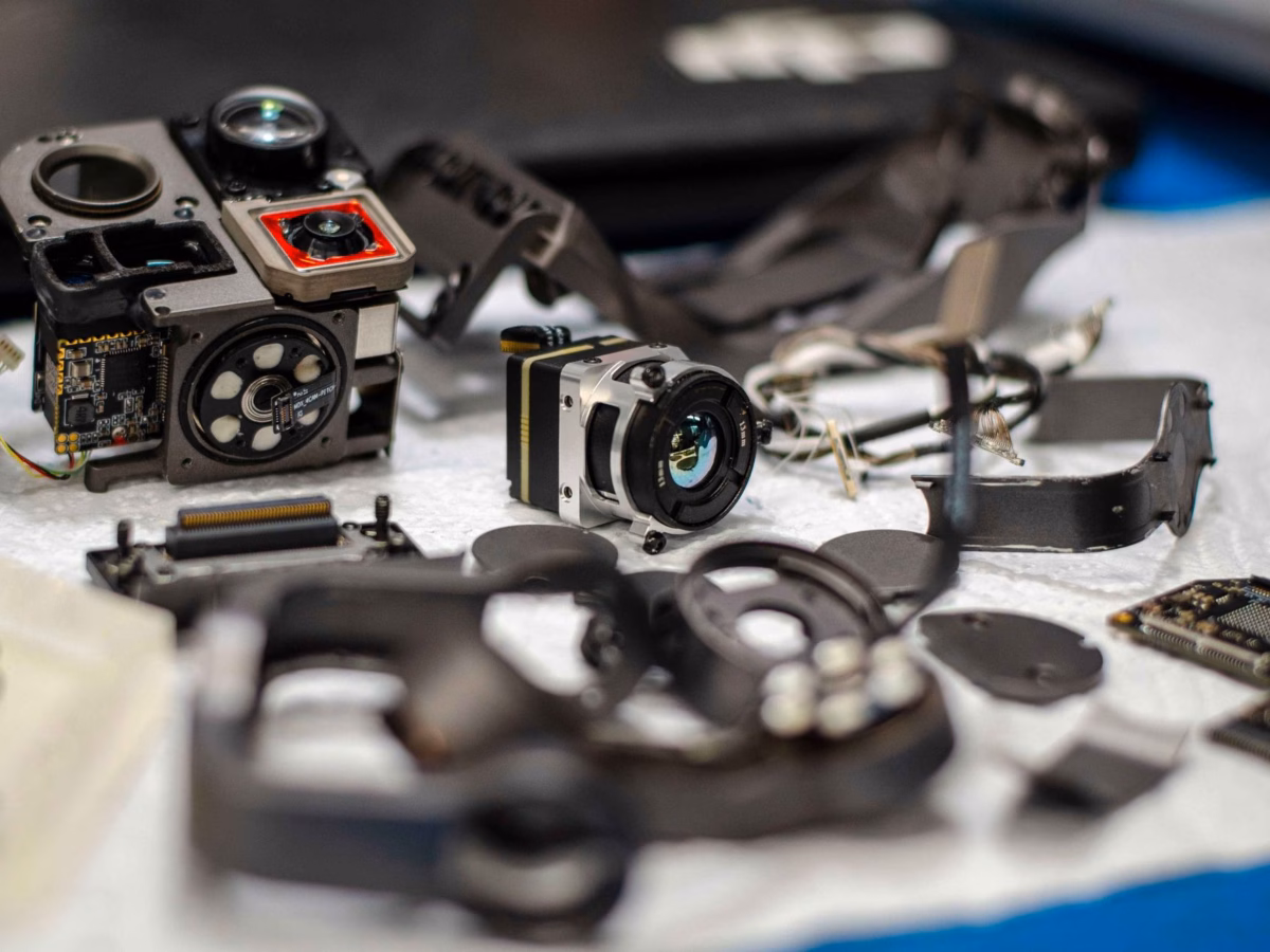
| Technical Specification | Uncooled Infrared RJ45 CVBS RTSP IP 640*512 ASIC Module | Uncooled LWIR USB Mini 640*512 Camera Core Module |
|---|---|---|
| Product Image | 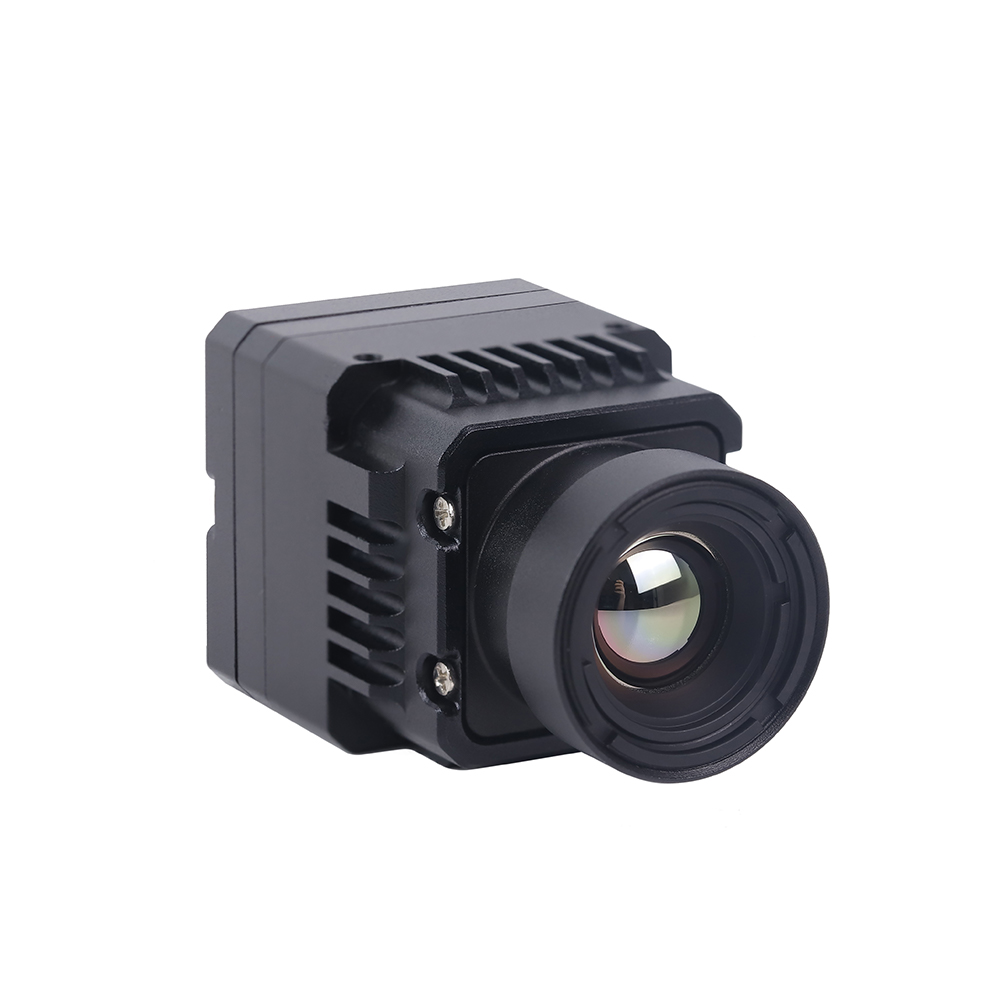 |
 |
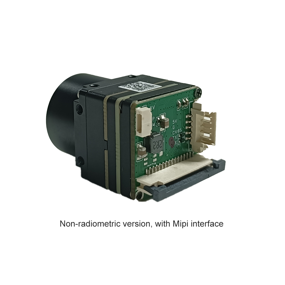
| Primary Video Interface | RJ45 Ethernet, CVBS Analog Out | USB 2.0 (Mini USB Interface) |
| Native Resolution | 640 × 512 Uncooled FPA | 640 × 512 Uncooled FPA (640 × 480 optional) |
| Pixel Pitch | 12μm | 12μm |
| Sensor Type | Uncooled VOx Microbolometer | Uncooled VOx Microbolometer |
| Supported Protocols | RTSP, RTP, TCP/IP, UDP, DHCP, HTTP | UVC (USB Video Class), standard WebCam |
| Onboard ISP Processing | ASIC-based NUC, AGC, DDE, Pseudo-Color | ASIC-based NUC, AGC, Pseudo-Color, Bad Pixel Correction |
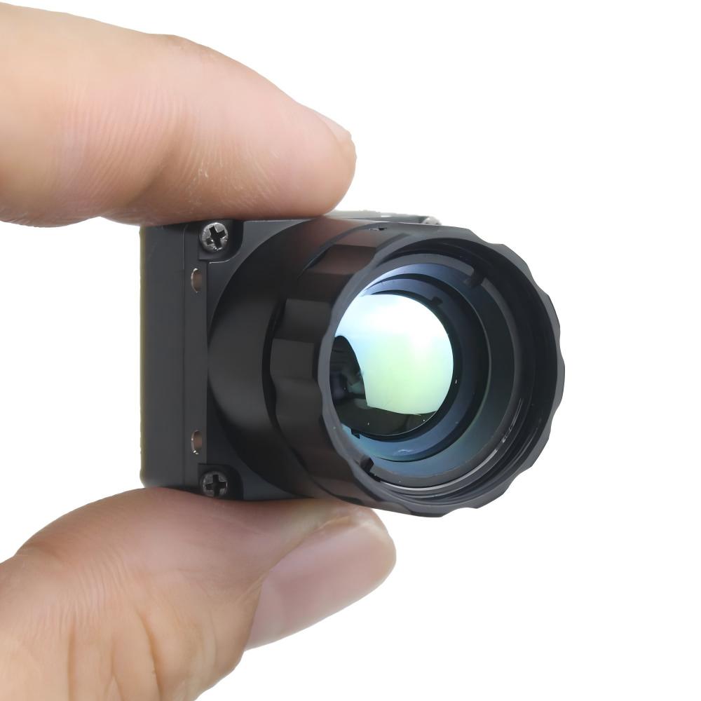
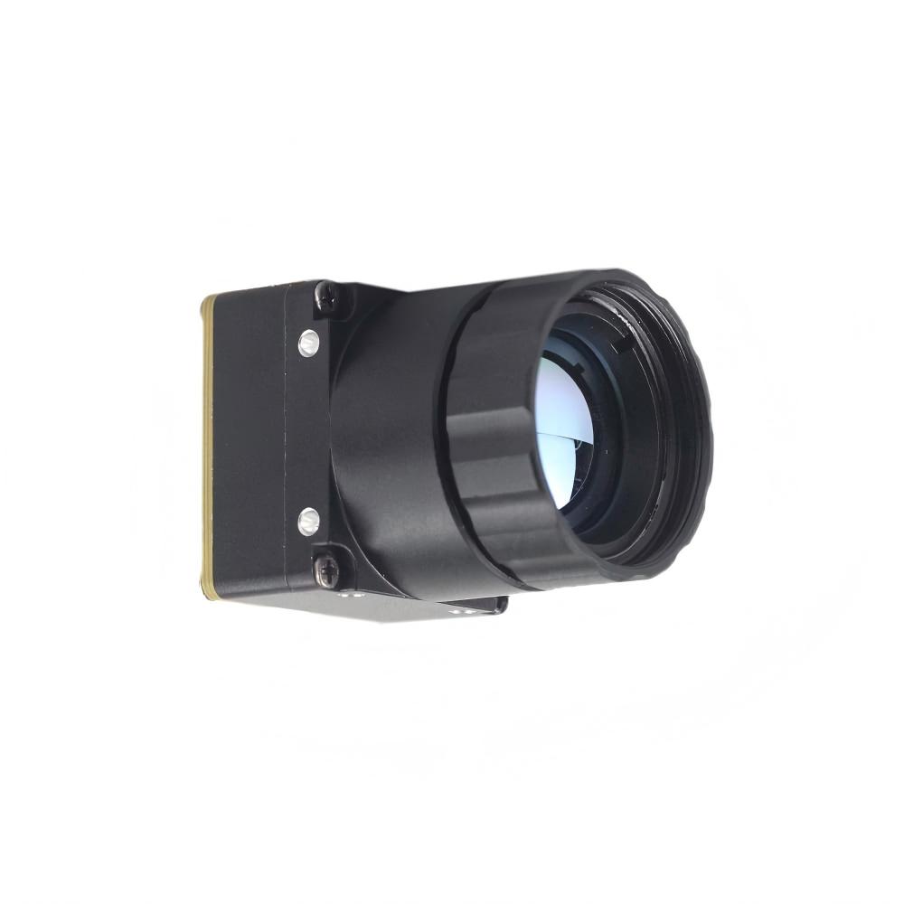
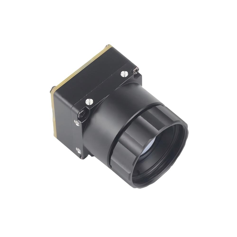
| Dimensions (L x W x H) | Compact integrations | 21mm × 21mm (Ultra-miniature footprint) |
| Lens Focal Length Options | Optimized for Drones & Long-Range Monitoring | 5mm, 9mm, 13mm, 18mm, 35mm, 50mm, 75mm, 100mm, 150mm |
| Best-Use Application | Long-distance security, remote IP, drone RTSP streams | Low-latency local AI, compact drones, handheld analyzers |
Uncooled Infrared RJ45 CVBS RTSP IP 640*512 ASIC Module Showcase
If you are building distributed systems or drone arrays, this RJ45 RTSP IP core is an absolute workhorse. It features an on-board ASIC that handles your non-uniformity correction (NUC), gain matching, and local digital contrast algorithms on-the-fly. By embedding an efficient compression block, it outputs highly fluid H.264 video streams directly over local network switches. This lets you setup remote thermal stations with zero frame drops.
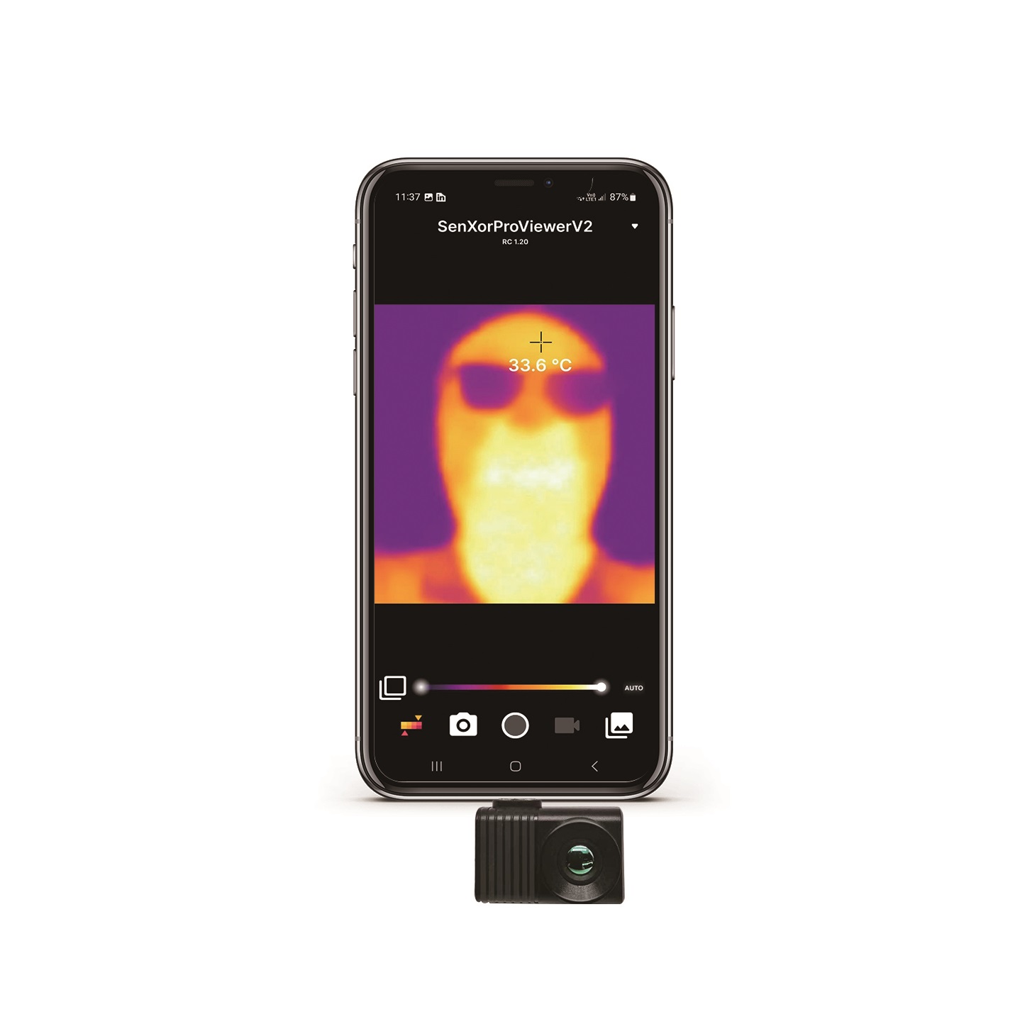
Uncooled LWIR USB Mini 640*512 Camera Core Module Showcase
If space is tight and you need absolute minimum latency, you go with this USB Mini module. Measuring a mere 21mm by 21mm, it is tiny enough to bolt into compact gimbal frames or pocket-sized inspection gear. Because it is a plug-and-play UVC device, your Raspberry Pi treats it like a native camera. It supports an unbelievable range of Germanium and Chalcogenide lenses, from a wide-angle 5mm lens up to a tight 150mm telephoto setup.
5. Building an Edge AI & Linux Streaming Pipeline on Raspberry Pi
When you're trying to build a stable computer vision stack on the Raspberry Pi, your choice of code architecture will make or break your frame rate. Let's make one thing clear: if you are trying to write basic Python loops that grab frames, convert formats, and pass arrays sequentially, your pipeline will drag. You'll run into garbage collection lag, queue blockages, and high system latency.
Optimization Strategies for Raspberry Pi (Debian Bullseye/Bookworm)
- ✅ Stop Reading Frames in the Main Thread: If your AI inference blocks for 40ms, your ingest pipeline drops subsequent frames. Always run your camera interface inside a dedicated high-priority daemon thread.
- ✅ Bypass CPU Decompression: Use hardware acceleration blocks via GStreamer APIs. When processing RTSP streams, use
v4l2h264decorv4l2m2mto keep compression processing off your arm cores. - ✅ Drop Frames on Overrun: Never let queue buffers build up. If your AI model takes too long to run, drop old frames and grab the newest frame from the thread buffer immediately (using a zero-buffer appsink).
Practical Code Implementation
Here is a battle-tested Python class utilizing robust GStreamer pipelines to ingest both local USB UVC feeds and network RTSP streams with zero frame lag. It uses multi-threaded buffers to ensure you always have instant access to the latest raw frame without stuttering.
import cv2
import sys
import time
import threading

class ThermalPipelineIngester:
    def __init__(self, source_type="UVC", address="/dev/video0", rtp_latency=100):
        """
        Initializes an optimized frame ingestion stream under Linux.
        source_type: "UVC" for local mini USB modules, "RTSP" for ethernet modules.
        address: Device path (like '/dev/video0') or network RTSP URL.
        """
        self.source_type = source_type.upper()
        self.address = address
        self.rtp_latency = rtp_latency
        self.frame = None
        self.is_running = False
        self.lock = threading.Lock()
        self.cap = None

    def _get_gstreamer_pipeline(self):
        """
        Builds optimized GStreamer launch strings.
        Forces the hardware pipeline to bypass heavy CPU thread conversion bottlenecks.
        """
        if self.source_type == "RTSP":
            # RTSP injection using system hardware decoders (v4l2m2m/v4l2h264dec)
            gstreamer_str = (
                f"rtspsrc location={self.address} latency={self.rtp_latency} ! "
                "rtph264depay ! h264parse ! "
                "v4l2h264dec ! "
                "video/x-raw, format=I420 ! "
                "videoconvert ! video/x-raw, format=BGR ! "
                "appsink drop=true sync=false"
            )
            return gstreamer_str
        elif self.source_type == "UVC":
            # Native UVC configuration to pull 640x512 streams
            gstreamer_str = (
                f"v4l2src device={self.address} ! "
                "video/x-raw, width=640, height=512, format=YUY2 ! "
                "videoconvert ! video/x-raw, format=BGR ! "
                "appsink drop=true sync=false"
            )
            return gstreamer_str
        else:
            raise ValueError("Invalid source type configuration provided.")

    def start_ingestion(self):
        self.is_running = True
        gstreamer_cmd = self._get_gstreamer_pipeline()
        print(f"[INFO] Launching GStreamer Core Engine:")
        print(f"       {gstreamer_cmd}")

        # Open source utilizing GStreamer integration backend
        self.cap = cv2.VideoCapture(gstreamer_cmd, cv2.CAP_GSTREAMER)

        if not self.cap.isOpened():
            print("[ERROR] Failed to compile and open camera via GStreamer.")
            self.is_running = False
            return False

        # Spawn thread to keep pulling frames and prevent buffer clogging
        self.thread = threading.Thread(target=self._update_frame_buffer, daemon=True)
        self.thread.start()
        return True

    def _update_frame_buffer(self):
        while self.is_running:
            ret, tmp_frame = self.cap.read()
            if not ret:
                print("[WARNING] Frame capture timeout. Retrying link...")
                time.sleep(0.01)
                continue

            with self.lock:
                self.frame = tmp_frame

    def get_latest_frame(self):
        with self.lock:
            return self.frame.copy() if self.frame is not None else None

    def stop(self):
        self.is_running = False
        if self.cap:
            self.cap.release()
        print("[INFO] Camera capture stopped.")

# Driver execution loop demonstrating live AI frame ingestion
if __name__ == "__main__":
    # To run local USB Module: source_type="UVC", address="/dev/video0"
    # To run IP Module: source_type="RTSP", address="rtsp://192.168.1.150:554/stream1"
    ingester = ThermalPipelineIngester(source_type="UVC", address="/dev/video0")

    if ingester.start_ingestion():
        print("[SUCCESS] Processing loop active. Press 'q' key to shut down visual feed.")
        start_time = time.time()
        frames_computed = 0

        try:
            while True:
                frame = ingester.get_latest_frame()
                if frame is not None:
                    frames_computed += 1

                    # Calculate true runtime loop speed
                    run_duration = time.time() - start_time
                    current_fps = frames_computed / run_duration if run_duration > 0 else 0

                    # ------------------------------------------------------------
                    # PLACE INFERENCE BLOCK HERE
                    # This is your entry hook for Edge models. Pass frame to:
                    # model_outputs = my_yolov8_detector(frame)
                    # ------------------------------------------------------------

                    # Overlay analytics on display frame
                    cv2.putText(frame, f"Analysis Stream FPS: {current_fps:.1f}", (15, 30),
                                cv2.FONT_HERSHEY_SIMPLEX, 0.7, (0, 0, 255), 2)

                    cv2.imshow("Raspberry Pi High-Res Industrial Thermal Feed", frame)

                if cv2.waitKey(1) & 0xFF == ord('q'):
                    break
        finally:
            ingester.stop()
            cv2.destroyAllWindows()
Mini 640×512 Thermal Imaging Core Demo Video
6. Deep-Dive B2B Technical FAQ
Why should I upgrade from low-resolution sensors like MLX90640 to a professional LWIR module for my Raspberry Pi?
Here's the deal: sensors like the MLX90640 are great for simple bench projects or checking if someone is walking through a doorway, but they fall flat when you need real spatial accuracy. At 32×24 resolution, you collect only 768 data points. When a drone is flying at 100 feet, or when you are monitoring complex factory machinery from across a room, a single target gets averaged out into a fuzzy, useless pixel blob. You can't run machine learning models like YOLO on that; there are no edge features or shapes to detect.
Upgrading to an uncooled 640×512 microbolometer gives you 327,680 real thermal pixels. That is over 400 times the information density. You get sharp physical outlines, clear thermal edges, and real target differentiation. Additionally, those consumer thermopile chips run over I2C, which introduces high latency and chokes your CPU. Professional modules communicate directly over UVC or Ethernet, using system-level drivers to offload your CPU and keep your frame rates fluid.
How do I stream real-time thermal video to a Raspberry Pi running Linux without lag?
In the shop, we see too many engineers screw this up by parsing raw socket streams line-by-line in single-threaded Python scripts. This creates massive memory-copy delays, causing lag to spiral out of control. To run zero-lag thermal feeds, you need to configure your ingest pipeline to use asynchronous threads and hardware-accelerated loops.
For USB UVC cameras, use the Video4Linux2 (V4L2) kernel API combined with GStreamer. For network modules, ingest your RTSP feeds using GStreamer as your OpenCV back-end and configure the buffer limits to 'drop-on-overrun'. This ensures that if your AI model slows down for a split second, your camera queue instantly throws away stale frames and serves up the newest, lowest-latency frame immediately.
What are the differences between CVBS, RTSP, and USB output in industrial modules?
Your physical integration requirements will dictate which output format you should choose:
- ⚙️ CVBS (Composite Video Baseband Signal): This is a standard analog television format. It has virtually no transmission lag and wires directly into long-range analog drone transmitters. The downside is that it requires an external analog-to-digital converter chip to interface with a Raspberry Pi, which is an extra point of failure and degrades image clarity.
- ⚙️ RTSP (Real-Time Streaming Protocol): This is an IP network stream compressed directly on the sensor core's ASIC using formats like H.264. This lets you run long Cat5e/Cat6 cables (over 300 feet) and stream directly to multiple switches and network systems. However, network processing and compression introduce a slight latency penalty (usually around 150ms).
- ⚙️ USB (UVC): This turns your module into a standard, driverless plug-and-play webcam. It is the easiest way to pull raw, high-speed digital frames directly into a local Raspberry Pi with near-zero latency, but you are physically restricted to standard USB cable lengths.
How do uncooled VOx microbolometers perform NUC (Non-Uniformity Correction) and why is it critical?
Look at how microbolometer pixels are built: they are tiny mechanical membranes suspended over a substrate, measuring tiny resistance changes caused by incoming heat. But here's the catch: as your device warms up under normal operation, the heat from your own processor boards, external components, and ambient temperature shifts causes the sensor's individual pixels to drift. This introduces fixed pattern noise (which looks like vertical streaks, ghosting, or a cloudy haze across your image).
To fix this, uncooled sensors use a Non-Uniformity Correction (NUC) routine. When the system detects a temperature drift, a small, voice-coil-driven mechanical shutter drops in front of the FPA for a fraction of a second. This shutter provides a perfectly uniform temperature card. The ASIC reads the pixel array, maps the variations from pixel to pixel, and writes a real-time calibration table. When the shutter snaps back open, the core subtracts this pattern from the incoming feed, giving you a clean, crisp thermal image.
📚 References & Further Reading
- Industry Standards & Electronics Manufacturer: Shenzhen ChiYi Electronics Co., Ltd.
- Industrial Lenses & Infrared Optomechanics: LightPath Technologies
- Alternative Product Options: Purpleriver Thermal Imaging Store Selection
- Related Guide: Can we convert a regular camera into a thermal imaging camera? From DIY beginners to professional level thermal imaging solutions