








How to Choose the Best Infrared Thermal Imaging Camera Module for Drones, Raspberry Pi, and Edge AI Integration
2026年7月3日
Best 256x192 25mm Thermal Camera Module for DIY Scopes & Drones: Cost-Effective Long-Range IR Sensor
2026年7月3日
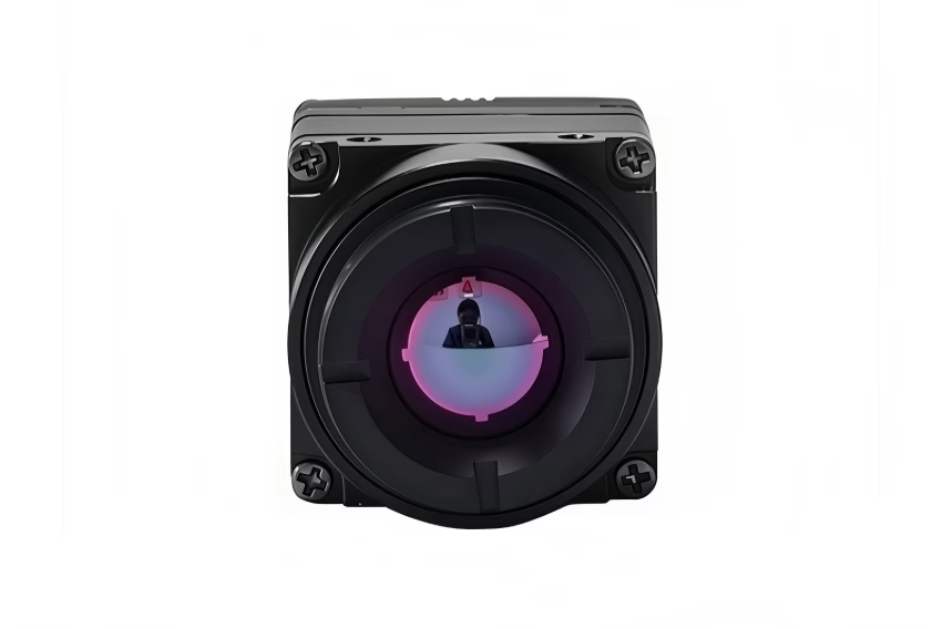
640 512 35mm Thermal Camera Module: The Ultimate B2B Integration Guide for Drones and Edge AI
For aerospace defense contractors, payload systems integrators, and Edge AI hardware developers, selecting the ideal thermal payload is an exercise in balancing spatial resolution, optical magnification, and the stringent constraints of Size, Weight, and Power (SWaP). Among the array of modern sensor configurations, the uncooled Long-Wave Infrared (LWIR) thermal camera module 640 512 35mm has emerged as the industry's sweet spot for medium-to-long-range surveillance, precision agriculture, power grid inspections, and tactical unmanned aerial systems (UAS). It delivers the optimal compromise between a sufficiently narrow field of view (NFOV) and high-density spatial data without requiring the massive chassis, cooling power, and cost associated with cryocooled MWIR systems.
Integrating these specialized sensor cores into modern drone gimbals and Edge AI pipelines requires a deep understanding of optical physics, physical interfaces (such as USB, RJ45 RTSP/IP, and MIPI CSI-2), and processing pipelines. This technical guide provides engineering firms and system architect leads with the exact specifications, mathematical trade-offs, electrical schematics principles, and programming interfaces required to successfully integrate uncooled 640x512 microbolometer cores into next-generation industrial edge solutions.
Look, in the shop, we don't look at thermal cores as plug-and-play webcams. They are precision radiometric instruments. When you are flying a multi-thousand-dollar airframe over critical infrastructure, guesswork gets expensive fast. Let's break down the actual engineering reality of making these sensors work seamlessly under real-world conditions.
Table of Contents
- 👉 Section 1: Optical & Spatial Physics of the 640x512 35mm Sensor Core
- 👉 Section 2: SWaP-C Optimization & Physical Drone Integration
- 👉 Section 3: Interface Protocols: Choosing USB, RTSP/IP, and MIPI CSI-2
- 👉 Section 4: Edge AI Software Engineering & Thermal Matrix Processing
- 👉 Section 5: Direct Comparison Matrix of Commercial LWIR Core Modules
- 👉 Section 6: Deep-Dive Integration FAQ
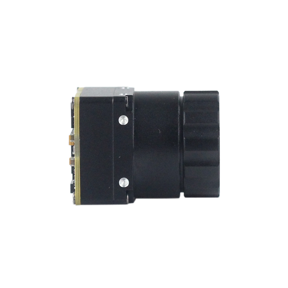
1. Optical & Spatial Physics of the 640x512 35mm Sensor Core
Understanding the mechanics of uncooled microbolometers is critical when evaluating a high-performance thermal camera module 640 512 35mm. Modern uncooled systems utilize a vacuum-packaged focal plane array (FPA) consisting of vanadium oxide (VOx) or amorphous silicon (α-Si) micro-resistors. These resistors register changes in resistance when exposed to radiant long-wave infrared energy (typically in the 8μm to 14μm spectral band). The performance of these sensors is governed by pixel pitch, thermal sensitivity (NETD), and optical system parameters.
The Spatial Resolution Advantage: 640x512 vs. 384x288
Here's the deal: a native 640x512 sensor array features exactly 327,680 active pixels. In comparison, a baseline 384x288 sensor yields just 110,592 pixels. Upgrading to a 640-class thermal module delivers an exact 2.96× (nearly 3×) increase in raw pixel density. This spatial jump is crucial for drone missions and automated target recognition (ATR) algorithms. While upscaling interpolation algorithms can artificially smooth a 384x288 frame, they cannot inject high-frequency spatial details or resolve sub-pixel high-contrast thermal gradients—such as a single loose core wire on a high-voltage distribution tower or a structural hot-spot during a search-and-rescue mission. Native pixels are critical for accurate predictive maintenance algorithms and tracking models.
Field of View (FOV) and Spatial Projection Math
For automated detection systems, calculating the field of view and spatial projection on the ground is essential. Let us calculate the true horizontal and vertical FOV of a thermal module utilizing a 12μm pixel-pitch, 640x512 array paired with a 35mm focal length germanium objective lens.
First, determine the physical dimensions of the active sensor area (W_sensor and H_sensor):
W_sensor = 640 pixels × 12μm = 7.68mm
H_sensor = 512 pixels × 12μm = 6.144mm
Using the trigonometric focal equation:
FOV = 2 × arctan(d / (2 × f))
Where d is the active dimension of the sensor and f is the focal length (35mm):
HFOV = 2 × arctan(7.68mm / 70mm) ≈ 12.54°
VFOV = 2 × arctan(6.144mm / 70mm) ≈ 10.02°
This narrow HFOV (≈ 12.5°) behaves as an optical telephoto system. It specializes in isolating spatial thermal emissions at long range, projecting high pixel-density regions onto distant targets.
Johnson's Criteria (DRI) Model for a 35mm Lens
Johnson’s Criteria is the industry standard used to predict the probability of a human observer detecting, recognizing, or identifying a target with a specific sensor configuration. For an uncooled LWIR sensor (12μm pitch) with a 35mm objective lens, target performance is modeled using a critical target dimension of 1.8m (representing a standing adult human) and 2.3m (for a medium-sized utility vehicle). Evaluating these limits at 50% probability (N50):
- 🎯 Detection (DRI-D): Needs 1.5 pixels across the target's critical dimension.
- 🎯 Recognition (DRI-R): Needs 6.0 pixels across the target's critical dimension.
- 🎯 Identification (DRI-I): Needs 12.0 pixels across the target's critical dimension.
Using these variables, system engineers can calculate target ranges with high precision:
| Target Model | Critical Dimension | Detection Range (1.5px) | Recognition Range (6.0px) | Identification Range (12.0px) |
|---|---|---|---|---|
| Human Target | 1.8 meters | 5,250 meters | 1,312 meters | 656 meters |
| Utility Vehicle | 2.3 meters | 6,708 meters | 1,677 meters | 838 meters |
Determining correct optical requirements early prevents system integration failures. Developers looking to understand broader optimization techniques should consult our 2025 Thermal Module Guide, which covers baseline system configuration and low-cost development platforms.
2. SWaP-C Optimization & Physical Drone Integration
For multirotor and fixed-wing unmanned aerial vehicles (UAVs), payload mass acts as a direct multiplier on battery depletion, motor heat, and overall flight endurance. Thus, minimizing SWaP-C (Size, Weight, Power, and Cost) remains a core hardware engineering objective when choosing a thermal camera module 640 512 35mm.
Thermal stability is a huge pain point when designing drone payloads. Unlike visible-light CMOS sensors, uncooled microbolometers are incredibly sensitive to internal thermal gradients. Changes in the temperature of the module housing can introduce raw sensor drift, obscuring real target emissions with ghost images, noise patterns, or signal offset variations. To mitigate this issue in your mechanical designs, keep these specific strategies in mind:
- ⚙️ Passive Dissipation Arrays: Mount the 21mm × 21mm mini-sized core directly to the drone gimbal's structural aluminum frame using a high-efficiency thermal interface material (TIM). For example, use a 0.5mm phase-change silicone sheet or a graphite pad with high in-plane thermal conductivity (>1500 W/m·K). This ensures transfer of thermal energy away from the sensor's focal plane.
- ⚙️ Flat-Field Correction (FFC) Calibration: During flight, wind cooling and sun exposure cause localized casing fluctuations. To compensate, ensure the internal shutter mechanism activates dynamically based on temperature sensors situated directly on the FPA and lens assembly. This shutter-based NUC (Non-Uniformity Correction) eliminates temporal drifts and resets the pixel baseline offset.
Electromagnetic Interference (EMI) Shielding
Brushless motors, high-frequency electronic speed controllers (ESCs), and high-power telemetry transmitters and transceivers (such as 900MHz, 2.4GHz, or 5.8GHz links) operate in tight, noise-filled quarters on modern airframes. Uncontrolled EMI can manifest as horizontal scan lines, periodic noise, or synchronization losses over digital or analog video feeds.
To prevent signal degradation, the camera housing must be electrically continuous and grounded directly to the gimbal control board's system ground pool via an ultra-flexible micro-coaxial shielding braid or metal ground clips. Additionally, integrate miniature ferrite beads (e.g., Murata BLM series) and low-ESR ceramic capacitors (10μF and 0.1μF in parallel) directly at the power input pins of the module’s custom connector interface to reject electrical ripple from high-current motor draws.
Mechanical Shock Absorption & Stabilized Gimbal Mounts
To prevent jitter and high-speed motion blur, these modules require high-frequency vibration isolation. Secure the camera chassis into the gimbal bracket using low-durometer silicone damper rings or active vibration-damping grommets (typically Shore 30A to 45A polyurethane). A 35mm optical lens array shifts the module's balance point forward compared to standard 9mm wide-angle lenses. When modeling your gimbal, use computer-aided design (CAD) software to calibrate the 3D center of gravity at the intersection of the tilt and roll axes. This reduces continuous current load on the brushless servo motors and ensures stable, jitter-free footage under windy operating conditions.
3. Hardware Interface Protocols: Choosing USB vs. RTSP/IP vs. MIPI CSI-2
Understanding raw latency, processing bottlenecks, and pin-level complexity is crucial when choosing a transmission interface for your B2B integration. Below is an engineering trade-off analysis of the three primary interfaces used by a thermal camera module 640 512 35mm in modern drone systems.
| Interface Protocol | Max Throughput | Video Latency | Max Cable Length | B2B Implementation Complexity |
|---|---|---|---|---|
| USB 2.0 / USB-C (UVC) | 480 Mbps | 80 - 120 ms | < 3 meters | Minimal (Standard UVC Drivers) |
| RTSP / IP (RJ45) | 100 / 1000 Mbps | 150 - 250 ms | < 100 meters | Medium (Socket Config & Compression) |
| MIPI CSI-2 | 1.5 Gbps / lane | < 10 ms | < 15 cm | High (Requires Custom Kernel Drivers) |
1. USB 2.0 / Type-C (UVC Class Implementation)
Choosing a USB-based module, such as the Mini 640 LWIR Core, simplifies your hardware development cycle. Operating as a standard USB Video Class (UVC) device, it mounts directly as /dev/video0 on Linux kernels, requiring no proprietary video framegrabbers or customized interface drivers. This standard driver-class support makes it highly compatible with embedded computers like the NVIDIA Jetson series or Raspberry Pi platforms, enabling rapid software prototyping for commercial field testing.
2. RJ45 / RTSP IP Streaming (ASIC-Enabled Modules)
For infrastructure networks, industrial machinery yards, or long-range analog/digital tethered drone structures, models with integrated ASICs provide native standard IP-based processing. The RTSP (Real-Time Streaming Protocol) stack compresses raw thermal pixels into high-efficiency H.264/H.265 streams over an IP network, allowing long-distance routing over standard CAT5e/CAT6 Ethernet lines. This configuration is widely deployed in industrial perimeter security, substation monitoring, and fixed drone docking stations where network integration and multi-camera streams must converge on a centralized control center.
3. Native MIPI CSI-2 (Mobile Industry Processor Interface)
For tactical UAV micro-gimbals and spatial target tracking, even a 100ms video lag can cause guidance deviations or target loss during fast maneuvers. A MIPI CSI-2 (2-lane or 4-lane) thermal sensor module bypasses the USB serialization layers and Ethernet encoding loops, transmitting raw digital frame matrices directly into the MIPI receiver of an application processor (such as an Nvidia Jetson Orin or Raspberry Pi). This reduces total internal transport latency to less than 10ms, which is critical for real-time Edge AI inference, automated targeting, and fast dynamic gimbal stabilization loops.
For engineers evaluating raw custom construction vs. off-the-shelf module integration, see our comprehensive discussion in the DIY vs Professional Thermal Solutions Conversion Guide.
4. Edge AI Software Engineering & Thermal Matrix Processing
Integrating a high-resolution, long-range thermal camera module 640 512 35mm into an edge AI platform like the Nvidia Jetson Orin requires a low-overhead, multi-threaded software architecture. This structure must maintain a consistent 30 Hz raw frame throughput while running computer vision algorithms and model inference. The software framework process relies on libraries like OpenCV and specialized frame grabbing modules to target region-of-interest analysis.
Below is a production-grade Python implementation designed for embedded edge processors. It captures raw thermal streams, normalizes the bit depth to an 8-bit visual scale, applies a Contrast Limited Adaptive Histogram Equalization (CLAHE) process to resolve thermal footprints at a distance, and highlights overheating thermal targets:
import cv2
import numpy as np
import logging
import sys

# Configure logging for remote terminal deployment
logging.basicConfig(level=logging.INFO, format='[%(asctime)s] [%(levelname)s] %(message)s')

class ThermalAISystem:
    def __init__(self, device_index=0, frame_width=640, frame_height=512):
        self.device_index = device_index
        self.width = frame_width
        self.height = frame_height

        # Initialize OpenCV capture device using V4L2 backend
        self.cap = cv2.VideoCapture(self.device_index, cv2.CAP_V4L2)
        if not self.cap.isOpened():
            logging.error(f"Failed to bind thermal camera framegrabber to device index: /dev/video{self.device_index}")
            sys.exit(1)

        # Configure video format parameters
        self.cap.set(cv2.CAP_PROP_FRAME_WIDTH, self.width)
        self.cap.set(cv2.CAP_PROP_FRAME_HEIGHT, self.height)

        # Initialize CLAHE engine for high-frequency contrast optimization
        self.clahe_engine = cv2.createCLAHE(clipLimit=3.5, tileGridSize=(8, 8))
        logging.info(f"Thermal AISystem successfully initialized: 640x512 resolution tracking.")

    def run_pipeline(self):
        try:
            while True:
                ret, frame = self.cap.read()
                if not ret:
                    logging.warning("Failed to grab physical frame from thermal core channel.")
                    continue

                # Check for 14-bit or 16-bit raw digital arrays, fallback to standard frame
                if frame.dtype == np.uint16 or len(frame.shape) == 2:
                    # Raw radiometric values directly from sensor
                    gray_frame = frame
                else:
                    # Convert standard color channel input to grayscale representation
                    gray_frame = cv2.cvtColor(frame, cv2.COLOR_BGR2GRAY)

                # Ensure the frame resolution meets specification targets
                if gray_frame.shape[0] != self.height or gray_frame.shape[1] != self.width:
                    gray_frame = cv2.resize(gray_frame, (self.width, self.height), interpolation=cv2.INTER_LINEAR)

                # Normalize raw 12-bit/14-bit sensor array values into standard 8-bit dynamic range
                normalized_frame = cv2.normalize(gray_frame, None, 0, 255, cv2.NORM_MINMAX, dtype=cv2.CV_8U)

                # Apply CLAHE to resolve far-field structures
                contrast_enhanced = self.clahe_engine.apply(normalized_frame)

                # Apply high-contrast pseudo-coloring (Jet or Inferno)
                colored_render = cv2.applyColorMap(contrast_enhanced, cv2.COLORMAP_JET)

                # Establish warning threshold values for hot spot tracking
                _, threshold_mask = cv2.threshold(contrast_enhanced, 230, 255, cv2.THRESH_BINARY)

                # Segment targets using contour extraction
                contours, _ = cv2.findContours(threshold_mask, cv2.RETR_EXTERNAL, cv2.CHAIN_APPROX_SIMPLE)

                # Extract target coordinates and overlay analytics
                for contour in contours:
                    if cv2.contourArea(contour) > 15:  # Filter out sub-pixel sensor noise
                        x, y, w, h = cv2.boundingRect(contour)
                        # Draw bounding box over target zones
                        cv2.rectangle(colored_render, (x, y), (x+w, y+h), (0, 0, 255), 2)
                        cv2.putText(colored_render, "OVERHEATING TARGET DETECTED", (x, y - 10),
                                    cv2.FONT_HERSHEY_SIMPLEX, 0.4, (0, 0, 255), 1)

                # Render analytical output stream to screen
                cv2.imshow("Industrial Thermal Core Feed", colored_render)

                # Terminate execution loop safely on 'q' press
                if cv2.waitKey(1) & 0xFF == ord('q'):
                    break

        except KeyboardInterrupt:
            logging.info("Thermal processing pipeline terminated manually.")
        finally:
            self.cap.release()
            cv2.destroyAllWindows()
            logging.info("Hardware framework released safely.")

if __name__ == "__main__":
    system = ThermalAISystem(device_index=0)
    system.run_pipeline()
5. Commercial & Structural Comparison Table of Core Modules
The following integrated product profiles represent the industry-standard uncooled microbolometer sensor engines currently in production. Each unit utilizes advanced readout integrated circuits (ROIC) to deliver high spatial resolution and robust environmental durability.

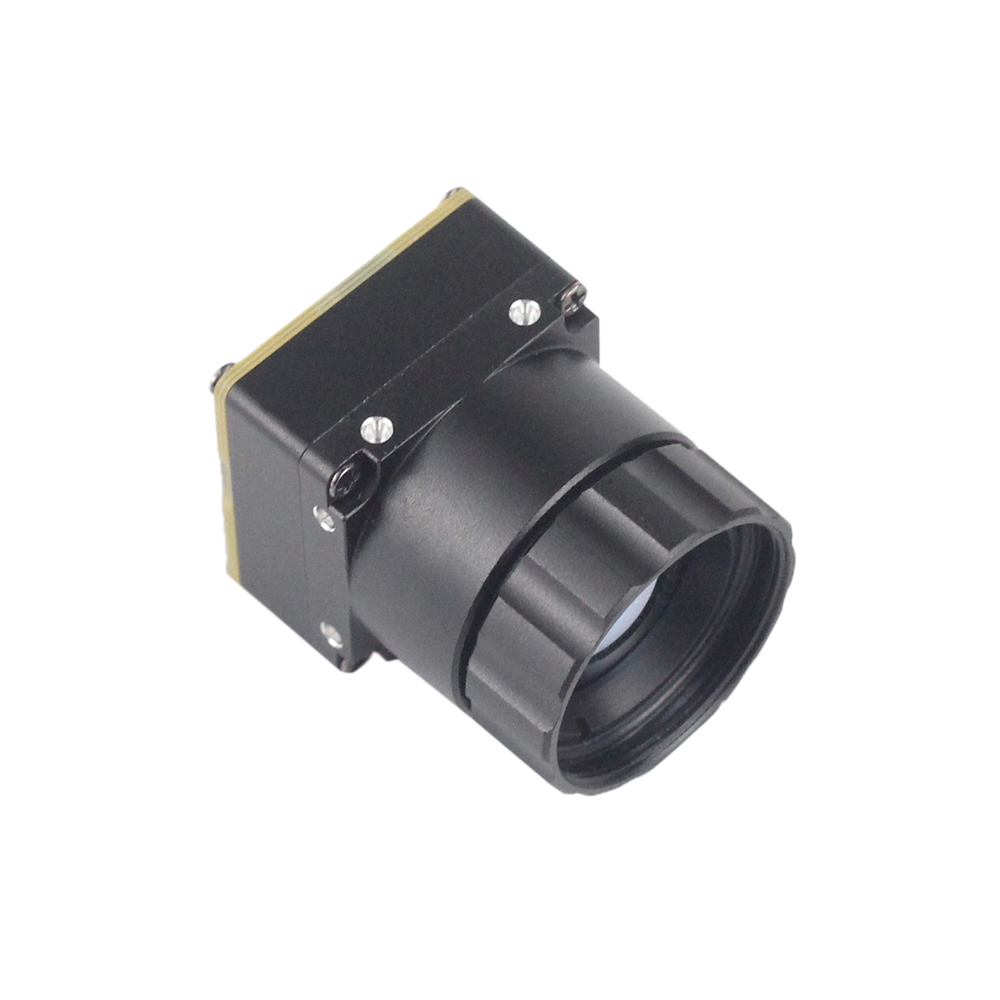
Uncooled LWIR USB Mini 640*512 Thermal Imaging Camera Core Module For Drones Similar To DJI
This ultra-compact uncooled LWIR core module features an incredibly small structural form factor measuring just 21mm * 21mm. Designed for deep physical systems integration inside weight-constrained UAV gimbals and multirotor airframes, it delivers exceptionally sharp, high-contrast thermal imaging at a minimal hardware cost.
Equipped with broad multi-lens support (featuring 5/9/13/18/35/50/75/100/150mm lens configurations), it is an exceptionally versatile development platform. Operating natively at 640*512 (or 640*480 optional) output resolution, this module is highly adaptable to extreme environments, providing consistent calibration reliability under active flight conditions.

Uncooled Infrared RJ45 CVBS RTSP IP 640*512 Thermal Sensor Camera Module
Designed for professional industrial network applications, this integrated uncooled infrared mini 640*512 module features an on-board ASIC pipeline optimized for direct IP-based data transmission. It supports native RJ45 network streaming, CVBS physical analog video output, and standard RTSP video feeds.
This hardware architecture enables remote network configuration and streaming, bypassing the need for an external, high-power application processor at the edge. It is ideal for stationary perimeter monitoring, heavy industrial plant automation, and tethered military-grade aerial surveillance arrays.
6. Deep-Dive Integration FAQ
Why choose a native 640x512 35mm thermal module over 384x288 or upscaled resolutions?
Choosing a native 640x512 sensor over a lower-resolution core provides a critical performance gain that cannot be replicated by software interpolation. A 384x288 array yields 110,592 spatial sensing points on the focal plane. In contrast, a native 640x512 array yields 327,680 points—exactly 2.96 times more raw pixel data. When paired with a 35mm lens, the physical pixel pitch (typically 12μm) determines the spatial sampling frequency of your sensor.
Using a 35mm lens narrows the horizontal field of view to 12.5°, concentrating the active pixels on distant targets. This optical design allows the module to operate at its full diffraction limit, resolving high-frequency thermal anomalies (like loose distribution clamps or sub-surface infrastructure defects) that software-upscaled 384x288 frames would smooth over. Software interpolation cannot inject raw physical data; thus, native pixels are indispensable for accurate, reliable automated target recognition (ATR) and predictive maintenance models.
How do you stream low-latency, real-time thermal video from this module to a Raspberry Pi or custom embedded system?
To stream real-time, low-latency video from a thermal camera module 640 512 35mm to an embedded system, developers must optimize the hardware-to-software data path. Standard Linux drivers use a multi-buffer queue (V4L2_BUFF_TYPE_VIDEO_CAPTURE) that can introduce up to 100ms of latency due to processing-intensive abstraction layers. To eliminate this bottleneck, configure your video capture engine to use double-buffering (allocating exactly 2 frame buffers) and fetch frames using Direct Memory Access (DMA).
Additionally, use a dedicated frame-grabbing thread running at the sensor's native frame rate (such as 30Hz or 60Hz) to constantly update an exchange frame buffer in system memory. Your main Edge AI inference or video rendering loops can then query this shared buffer asynchronously. This keeps the camera's capture thread unblocked and prevents frames from queuing up in system RAM, resulting in ultra-low streaming latencies (often under 20ms over a native MIPI CSI-2 or optimized USB bus).
Is this 35mm thermal core lightweight enough for compact drone gimbals?
Yes, uncooled 640x512 thermal camera modules are designed specifically to meet the strict SWaP (Size, Weight, and Power) requirements of small drone gimbals. The core PCB layout is highly compact, measuring just 21mm × 21mm and weighing only a few grams. The primary weight component is the specialized 35mm germanium lens array, which brings the total assembly weight to approximately 45 to 85 grams depending on the rugged housing style and physical aperture rating.
Because a long-range 35mm germanium lens shifts the center of gravity forward, avoid mounting the camera flat against the tilt axis plate. Instead, use slotted camera mounting brackets to dial in the camera's position along its physical longitudinal axis. Balances should be calibrated using CAD modeling and validated on a static gimbal rig. Ensuring proper balance on the pitch and roll axes minimizes holding currents, prevents motor overheating, and extends the flight times of drone systems.
📚 References & Further Reading
- Industry Standard: Computer vision and raw matrix operations powered by OpenCV Library Core SDK
- Industry Standard: High-performance embedded hardware support from Arducam Embedded Imaging
- Related Guide: Comprehensive developer guide on 2025 Thermal Module low-cost fast integration models for engineers
- Related Guide: Technical insights on custom hardware in how to build professional-level thermal imaging solutions





