Analog Thermal Camera Core Guide: Low-Latency CVBS Modules for FPV, DIY Optics & OEM
2026年9月23日
Radiometric Thermal Camera Module: OEM Integration & Raw Temperature Data Guide
2026年9月24日
Thermal imaging has transitioned from specialized, high-cost military defense systems to an indispensable component of modern embedded engineering, robotics, and industrial automation. At the core of this transition is the uart thermal camera module—a compact, electro-optical sensor package that integrates a long-wave infrared (LWIR) focal plane array, readout electronics, on-board digital signal processing, and a universal asynchronous receiver-transmitter (UART) physical communication interface. Unlike bulky consumer-grade infrared cameras or high-bandwidth USB/GigE vision devices that demand power-hungry host operating systems, a UART-driven infrared sensor module bridges the gap between raw microbolometer physics and lightweight microcontroller units (MCUs) or edge-AI companion computers.
For systems engineers designing autonomous unmanned aerial vehicles (UAVs), remote environmental monitoring nodes, handheld tactical reconnaissance instruments, or high-density electrical switchgear monitors, communication overhead and power budgets are critical constraints. High-speed serial interfaces like UART allow embedded designers to control camera calibration parameters, trigger shutter-based non-uniformity corrections (NUC), query region-of-interest (ROI) temperatures, and transmit diagnostic telemetry over simple two-wire or four-wire serial buses. When paired with complementary analog video feeds (such as CVBS) or secondary high-speed digital buses (such as SPI or MIPI), the UART interface functions as the dependable nervous system of the thermal vision subsystem.
Spis treści
- 👉 1. Architecture & Protocol Mechanics of UART Thermal Camera Modules
- 👉 2. Core Thermal Imaging Sensor Technologies: LWIR, Microbolometers, and Optics
- 👉 3. Industrial Hardware Showcase: High-Precision UART Modules
- 👉 4. Interfacing UART Thermal Modules with Embedded Systems and Microcontrollers
- 👉 5. Aerospace, Defensive, and Industrial Deployment Scenarios
- 👉 6. Calibration, Radiometry, and Environmental Emissivity Compensation
- 👉 7. Troubleshooting, Noise Mitigation, and Signal Integrity Best Practices
- 👉 Często zadawane pytania (FAQ)
1. Architecture & Protocol Mechanics of UART Thermal Camera Modules
The universal asynchronous receiver-transmitter interface remains one of the most durable, deterministic, and noise-tolerant serial communication standards deployed in industrial instrumentation. When integrated into an infrared thermal imaging core, UART operates primarily as the control plane (and, in low-bandwidth or downscaled configurations, the data plane). Understanding the protocol stack, hardware transceivers, and firmware-level timing constraints is fundamental to building a robust embedded imaging architecture.
At the physical layer (OSI Layer 1), a UART thermal camera module operates using standard asynchronous framing: a start bit, 8 data bits, an optional parity bit (most industrial modules use no parity), and one or two stop bits (commonly referred to as 8-N-1). Logic voltage levels typically align with standard 3.3V Low-Voltage Transistor-Transistor Logic (LVTTL), though certain ruggedized aerospace modules incorporate industrial RS-232, RS-422, or differential RS-485 transceivers to support multi-drop topologies or long-distance wire runs exceeding several tens of meters across airframes or manufacturing plants.
Transmission speeds are fundamentally balanced between command latency and electrical noise immunity. Standard default baud rates are typically 115,200 bps, which provides adequate throughput for sending telemetry requests, reading ambient die temperatures, adjusting color palettes (such as White Hot, Black Hot, Ironbow, or Rainbow), and executing manual non-uniformity corrections. However, when an engineer configures the module to output full radiometric temperature matrices—where every pixel represents a calibrated 14-bit or 16-bit temperature integer—the baud rate must be elevated to high-speed UART configurations, such as 460,800 bps, 921,600 bps, or even multi-megabaud rates (e.g., 1.5 Mbps to 3.0 Mbps) supported by contemporary ARM Cortex-M7 or edge Linux microprocessors.
At the data link and transport layers, UART thermal camera modules implement proprietary or standardized packet structures. A typical command packet follows a rigorous byte-level sequence designed to prevent command corruption in electromagnetically noisy environments:
- ⚙️ Preamble / Frame Header: A fixed two-byte or three-byte synchronization sequence (e.g.,
0xAA 0x55lub0xEB 0x90) used by the receiver's state machine to identify the arrival of an incoming packet. - ⚙️ Device Identifier / Address: Supports multi-device bus configurations when operating over an RS-485 physical bus.
- ⚙️ Command ID / Function Code: Dictates the operation, such as triggering an internal calibration shutter, selecting a digital zoom ratio (1x, 2x, 4x, 8x), configuring thermal alarm thresholds, or requesting point-temperature extraction.
- ⚙️ Payload Length: An integer specifying the exact number of data payload bytes that follow, preventing buffer overrun vulnerabilities on embedded hosts.
- ⚙️ Data Payload: Variable-length configuration bytes, such as target coordinate inputs (X, Y) for spot temperature queries or polynomial coefficient arrays for user calibration.
- ⚙️ Error Detection / Checksum: An 8-bit checksum, 16-bit CRC (Cyclic Redundancy Check), or CRC-CCITT value calculated across the header and payload to guarantee packet integrity before execution.
Because UART is fundamentally asynchronous, timing jitter, clock frequency drift, and buffer overruns present serious operational challenges if the host microcontroller firmware relies on naive blocking input/output operations. High-reliability industrial software designs utilize Direct Memory Access (DMA) paired with circular ring buffers tied to the microcontrollers UART idle-line detection interrupt. This enables zero-copy packet ingestion, permitting the MCU to parse complete thermal command frames without stalling critical real-time control loops, motor drivers, or flight stabilization software.
2. Core Thermal Imaging Sensor Technologies: LWIR, Microbolometers, and Optics
To fully leverage a UART thermal camera module, system designers must grasp the underlying physical principles governing infrared detection. All non-cryogenic (uncooled) commercial and industrial thermal camera cores operate within the Long-Wave Infrared (LWIR) atmospheric transmission window, spanning the 8 μm to 14 μm electromagnetic spectrum. This optical band is optimal because terrestrial objects, machinery, human bodies, and terrain emit blackbody radiation that peaks precisely within this wavelength range at standard ambient temperatures according to Planck's Law and Wien's Displacement Law.
The primary transducer inside an uncooled module is the microbolometer Focal Plane Array (FPA). A microbolometer array consists of thousands of microscopic detector elements suspended above a silicon substrate by thin, thermally isolated support legs. When infrared radiation strikes the active absorbing layer of a pixel, the material absorbs the photons, inducing a measurable increase in its physical temperature. This temperature shift alters the electrical resistance of the material. A Readout Integrated Circuit (ROIC) bonded directly beneath the array applies a precise bias voltage or current, measuring the change in resistance across every pixel in the matrix to construct a raw thermal frame.
Two primary semiconductor materials dominate modern microbolometer fabrication:
- ✅ Tlenek wanadu (VOx): VOx detectors deliver an exceptional Temperature Coefficient of Resistance (TCR), high sensitivity, and low 1/f flicker noise. This results in superior thermal resolution, characterized by a lower Noise Equivalent Temperature Difference (NETD). Modules utilizing VOx detectors routinely achieve NETD values below 40 mK or 50 mK, meaning they can resolve minute temperature variations of less than 0.04°C. This makes VOx the industry standard for tactical UAV reconnaissance, industrial predictive maintenance, and medical screening.
- ✅ Krzem amorficzny (a-Si): While a-Si detectors exhibit slightly lower thermal sensitivity and higher noise floors compared to VOx, their manufacturing process integrates cleanly into standard CMOS fabrication lines. This yields lower production costs and high structural uniformity, making them common in high-volume, cost-constrained commercial security products.
Another fundamental metric is rozstaw pikseli, defined as the center-to-center distance between adjacent detector pixels on the FPA. Legacy sensors utilized a 25 μm or 17 μm pixel pitch. Modern state-of-the-art miniature cores have advanced to 12 μm pixel pitch architectures. Shrinking the pixel pitch allows a 384×288 or 640×512 resolution detector to fit onto a drastically smaller physical die. This reduction directly decreases the required diameter and focal length of the accompanying optical lenses, drastically reducing the overall module mass, volume, and bill-of-materials cost.
Standard optical glass (such as fused silica or borosilicate) is completely opaque to the LWIR spectrum. Therefore, an uncooled UART thermal camera module must utilize specialized infrared optical materials, predominantly optical-grade monocrystalline Germanium (Ge), Chalcogenide glasses, or Zinc Selenide (ZnSe). Germanium boasts a remarkably high index of refraction (approximately 4.0), enabling optical engineers to design thin, compact lens elements with short focal lengths and high optical throughput (f/1.0 to f/1.2 apertures). To withstand harsh operational environments—such as sandstorms, high humidity, or acidic chemical atmospheres—these lenses are treated with anti-reflective (AR) and diamond-like carbon (DLC) protective coatings.
For specialized aerospace platforms, optical engineers frequently collaborate with specialized precision component vendors like Optyka wznosząca to source custom-engineered Germanium lens assemblies and optical coatings tailored for high-vibration and extreme thermal-shock environments.
3. Industrial Hardware Showcase: High-Precision UART Modules
Selecting the optimal UART thermal camera module demands a detailed evaluation of spatial resolution, radiometric measurement accuracy, physical interfaces, power consumption, and mechanical envelopes. Below are two industry-standard, uncooled microbolometer camera cores designed specifically for demanding embedded applications, autonomous drones, and field robotics.
Uncooled Mini 384×288 Thermal Camera Module For Drones
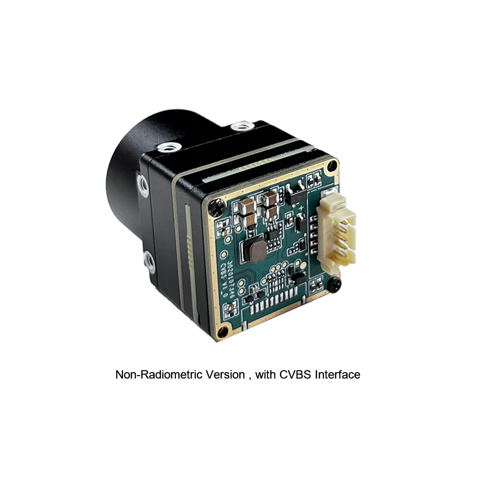
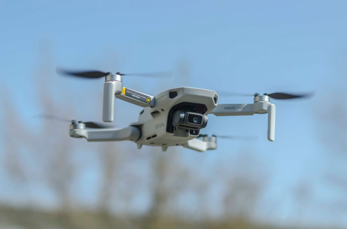
The MINI series infrared thermal imaging temperature measurement module is an ultra-compact, high-precision, universal online temperature measurement infrared thermal imager designed specifically for SWaP-constrained (Size, Weight, and Power) platforms. It integrates an advanced uncooled microbolometer detector delivering a 384×288 spatial resolution, providing over double the pixel density of standard entry-level sensors. This high resolution permits longer standoff detection distances, making it a premier solution for drone-mounted aerial surveillance, power line inspection, and autonomous search platforms.
Engineered with versatile multi-interface connectivity, the module features high-speed UART communication alongside an analog CVBS video output. Through the serial UART interface, an external microcontroller or flight autopilot (such as ArduPilot or PX4 running on STM32 hardware) can dynamically send configuration commands, initiate continuous non-uniformity correction cycles, set target emissivity values, and extract targeted temperature readings in real time. The simultaneous CVBS video output enables direct transmission through standard 5.8 GHz analog video transmitters or digital video encoders without burdening the host processor with video decoding tasks.
| Specyfikacja | Parameter Value |
|---|---|
| Rozdzielczość detektora | 384 × 288 pikseli |
| Typ detektora | Niechłodzony mikrobolometr LWIR |
| Zakres spektralny | 8 μm to 14 μm |
| Communication Interface | UART (Serial Command & Telemetry) |
| Video Output Formats | CVBS Analog Video (PAL / NTSC) |
| Główne zastosowania | Machine Vision, Safety Inspection, Intelligent Manufacturing, Airborne Drones |
Uncooled LWIR Mini 256×192 Thermal Imaging Camera Module Similar To DJI For Detecting Mines
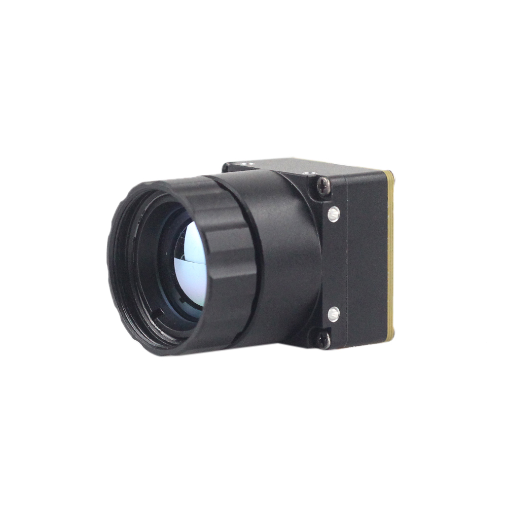
The Mini 256 Uncooled LWIR Thermal Camera Module delivers high-performance radiometric infrared sensing in an ultra-lightweight form factor similar to modern enterprise drone payloads. Utilizing an uncooled focal plane array with a 256×192 native resolution, this module is built to capture subtle differential radiation across natural ground surfaces. It is uniquely engineered for high-consequence detection tasks, such as uncovering buried landmines, improvised explosive devices (IEDs), and subsurface structural anomalies based on thermal inertia variations between disturbed earth and undisturbed ground.
The module captures infrared radiation and outputs a uniform, fully radiometrically calibrated thermal frame. Through its dedicated UART serial bus, systems integrators can configure deep radiometric look-up tables (LUTs), adjust digital detail enhancement (DDE) filtering parameters, poll minimum/maximum/average temperature markers, and receive serial status payloads. Its compact footprint and microscopic power draw make it exceptionally easy to integrate into micro-gimbals, wearable robotic rovers, and small quadcopters where payload capacity is restricted to a few tens of grams.
| Specyfikacja | Parameter Value |
|---|---|
| Rozdzielczość detektora | 256 × 192 Pixels |
| Sensor Physics | Uncooled LWIR High-Performance Detector |
| Radiometry Capability | Full-Array Radiometric Output with Calibration Metadata |
| Host Control Interface | UART TTL Serial Bus (Command / Response / Telemetry) |
| Format | Miniaturized SWaP-Optimized Drone Gimbal Core |
| Specialized Field Use | Subsurface Mine Detection, Precision Reconnaissance, Robotic Scouting |
4. Interfacing UART Thermal Modules with Embedded Systems and Microcontrollers
Implementing a successful integration between an embedded processor and a UART thermal camera module requires deliberate software and hardware architecture. In complex systems, designers typically adopt a hybrid topology: UART is designated as the control, configuration, and telemetry bus, while high-throughput parallel (DVP), SPI, or analog (CVBS) connections handle full-frame visual rendering.
For low-cost remote sensing nodes, developers frequently mate UART thermal cores with microcontrollers like the STMicroelectronics STM32 (Cortex-M4/M7 architecture), Espressif ESP32, or NXP i.MX RT crossover MCUs. In these low-power scenarios, the host MCU does not process a high-framerate visual stream. Instead, the MCU transmits periodic UART query commands requesting the maximum scene temperature, minimum scene temperature, and coordinates of thermal anomalies. The thermal module calculates these values using its internal digital signal processor and returns an aggregated telemetry payload over the serial bus. This design allows low-power IoT devices operating on lithium-ion batteries or solar panels to run continuous thermal health checks without drawing the power required to process digital video.
When high-level computer vision, automated target recognition (ATR), or user-facing graphical interfaces are required, single-board computers (SBCs) such as the Raspberry Pi, NVIDIA Jetson Orin Nano, or BeagleBone Black serve as the processing host. On a Linux-based SBC, the module's UART serial lines (TX and RX) connect directly to the hardware UART peripheral exposed on the host expansion header (e.g., /dev/ttyAMA0 lub /dev/ttyS0). Software developers leverage POSIX-compliant serial interfaces in C/C++ or asynchronous frameworks in Python (using libraries like pyserial i asyncio) to manage the bidirectional communication lifecycle.
Consider the firmware state machine required to maintain continuous synchronization with the thermal core. The following sequence must be executed within the host driver:
- ⚙️ Initialization: Configure the host UART peripheral for 8-N-1 communication at the camera's default baud rate (e.g., 115,200 bps). Enable hardware FIFO buffers and configure RX interrupt thresholds.
- ⚙️ Handshake & Ping: Transmit a query frame requesting the module's firmware version and hardware serial identifier. Verify that the response frame checksum validates correctly.
- ⚙️ Configuration: Issue configuration frames to establish radiometric parameters: set the emissivity parameter (ε) based on the target surface, set the reflected ambient temperature, and configure the internal non-uniformity correction mode (automatic shutter calibration vs. host-commanded shutter calibration).
- ⚙️ Continuous Polling Loop: If operating in telemetry mode, send an acquisition command (e.g.,
GET_SPOT_TEMP) at a steady frequency (e.g., 10 Hz to 30 Hz). Utilize DMA or non-blocking circular buffers to parse the returned packet. If a checksum error occurs, discard the frame and increment a fault counter. - ⚙️ Non-Uniformity Calibration Trigger: Monitor the camera core's internal focal plane temperature via its periodic telemetry packets. When the internal temperature drifts by more than a specified threshold (e.g., ±1.5°C), send a calibration command to trigger the mechanical shutter, allowing the ROIC to reset detector drift.
System designers developing compact mobile instruments can also evaluate plug-and-play USB interfaces, such as those used in modern portable mobile thermal modules, to contrast the SWaP-C profile of UART-based embedded sub-assemblies with consumer-oriented mobile peripherals.
5. Aerospace, Defensive, and Industrial Deployment Scenarios
The combination of micro-bolometer technology and low-overhead UART serial control has opened up critical operational applications across aerospace, defense, and heavy industry.
Subsurface Landmine and Threat Detection: In post-conflict zones and combat engineering operations, uncovering buried antipersonnel mines, unexploded ordnance (UXO), and improvised explosive devices is a dangerous, time-sensitive task. Uncooled LWIR modules, such as the 256×192 mini core, are deployed on autonomous ground rovers and low-altitude reconnaissance drones. The physics behind this detection method relies on differential thermal inertia. Buried foreign objects alter the heat conduction characteristics of the soil directly above them. During diurnal transitions—specifically at sunrise and sunset—the surface soil directly above a buried landmine heats up or cools down at a measurably different rate than the surrounding undisturbed terrain. The UART thermal module feeds precise radiometric temperature deltas to an on-board computer, highlighting subtle subsurface thermal signatures without exposing personnel to minefield hazards.
Aerial Search and Rescue (SAR): Search and rescue teams operating in dense forests, mountainous terrain, or maritime disaster zones rely on drone-mounted thermal camera modules. While visual-spectrum cameras fail in darkness, smoke, or thick canopy cover, a high-sensitivity (NETD < 40mK) 384×288 thermal core detects human body heat with exceptional clarity. The drone's flight controller uses the UART interface to automate thermal tracking, dynamically centering the gimbal on the hottest target in the visual frame. For a deeper examination of operational methodologies in humanitarian operations, review field studies on thermal search & rescue techniques.
Wildfire Containment & Thermal Perimeter Mapping: Aerial platforms equipped with compact thermal cores play a crucial role in combating wildland fires. Standard cameras are blinded by thick smoke plumes, making it impossible for incident commanders to locate active fire fronts or monitor post-containment smoldering hot spots. LWIR sensors pass unobstructed through particulate smoke, rendering the fire perimeter visible. Lessons learned from major historic disaster deployments, such as early aerial responses documented during the Santa Clara fire monitoring operations, demonstrate that continuous radiometric aerial surveillance is vital for protecting both civilian infrastructure and wildland firefighting personnel.
Predictive Maintenance in High-Voltage Electrical Infrastructure: High-voltage substations, distribution transformers, and commercial industrial switchgear are vulnerable to catastrophic failure caused by loose terminal connections, phase imbalances, and dielectric breakdown. Left unmitigated, these faults generate localized resistive heating (Joule heating, $P = I^2R$) that results in arc flashes or multi-million-dollar outages. Industrial monitoring enclosures integrate permanent, fixed-mount UART thermal camera modules directed at busbars and breaker connections. The module sends temperature telemetry over RS-485/UART to a programmable logic controller (PLC). If any contact point exceeds a pre-programmed threshold (e.g., 75°C), the PLC executes automated load shedding or alerts facility engineers before physical hardware failure occurs.
6. Calibration, Radiometry, and Environmental Emissivity Compensation
A standard thermal camera creates qualitative visualizations where pixel brightness or color palettes reflect relative temperature differences across a scene. Conversely, a modułami radiometrycznymi thermal camera module measures the actual quantitative temperature of every point within its field of view. Converting raw photon counts into calibrated temperature values requires an understanding of radiometry and calibration mathematics.
The total radiation received by the microbolometer sensor ($W_{total}$) is a composite of three separate radiative components:
$$W_{total} = \varepsilon \cdot \tau \cdot W_{obj}(T_{obj}) + (1 - \varepsilon) \cdot \tau \cdot W_{refl}(T_{refl}) + (1 - \tau) \cdot W_{atm}(T_{atm})$$
Gdzie:
- ⚙️ $\varepsilon$ (Emissivity): The relative ability of the target material's surface to emit thermal radiation compared to an ideal blackbody (ranging from 0.0 to 1.0). Highly polished metals (such as copper or aluminum) exhibit very low emissivity (≈0.05 to 0.15) and high reflectivity, while organic materials, painted surfaces, and electrical insulation have high emissivity (≈0.90 to 0.98).
- ⚙️ $\tau$ (Atmospheric Transmittance): The fraction of radiation that successfully traverses the atmosphere between the target and the camera lens, influenced by atmospheric path length, humidity, and airborne dust.
- ⚙️ $T_{obj}$ (Object Temperature): The actual kinetic surface temperature of the target being inspected.
- ⚙️ $T_{refl}$ (Reflected Ambient Temperature): Thermal radiation originating from surrounding hot sources (such as motors, furnace walls, or the sun) that bounces off the target surface into the camera optics.
- ⚙️ $T_{atm}$ (Atmospheric Temperature): Thermal energy emitted by the atmospheric gas layer directly into the optical path.
When an engineer communicates with an uncooled radiometric UART thermal camera module, the module's onboard DSP maintains internal polynomial calibration curves (derived during factory calibration against blackbody cavity standards at varying ambient temperatures). The host system can transmit calibration compensation commands across the UART link:
- ⚙️
SET_EMISSIVITY: Overwrites the internal coefficient $\varepsilon$ (typically represented as an integer percentage, e.g., 95 for 0.95). - ⚙️
SET_REFLECTED_TEMP: Inputs the background environmental temperature so the internal solver can mathematically subtract reflected ambient radiation. - ⚙️
SET_DISTANCE_COMP: Provides the object-to-camera distance (in meters) along with relative humidity, allowing the DSP to adjust the atmospheric transmission factor $\tau$.
Another fundamental aspect of microbolometer radiometry is Non-Uniformity Correction (NUC). Due to subtle semiconductor manufacturing tolerances, individual pixels on an uncooled microbolometer array exhibit varying voltage offsets and amplification gains. Over time, as the camera's internal chassis and focal plane array heat up during operation, the sensor develops fixed-pattern noise (FPN), producing a visible "grain" or spatial drift across the image. To resolve this, the module contains a miniature mechanical solenoid that periodically places a uniform, thermally stable black shutter flag in front of the detector for approximately 250 milliseconds. The module measures this uniform reference plane, calculates a new baseline offset matrix, and subtracts it from subsequent incoming frames. Through the UART protocol, host systems can either command this shutter calibration dynamically (e.g., preventing a calibration freeze during a critical UAV approach) or query the flag state to ensure automated calibrations only fire during safe mission windows.
7. Troubleshooting, Noise Mitigation, and Signal Integrity Best Practices
Integrating sensitive analog-to-digital electro-optical sensors into noisy industrial or robotic environments presents severe signal integrity challenges. UART is an unclocked, single-ended transmission standard that is inherently susceptible to external electromagnetic interference (EMI), common-mode ground noise, and capacitive line loading if not designed properly.
Below are critical electrical engineering practices to apply when designing systems around a UART thermal camera module:
- ✅ Proper Logic Level Shifting: Thermal imaging cores generally operate their digital I/O lines at 3.3V or 1.8V LVCMOS logic levels. If the host architecture (such as an industrial PLC or legacy 5V microcontroller) operates at 5V, never rely on passive resistor-divider networks for bidirectional serial communication. Resistor dividers introduce parasitic RC low-pass filters that round off the square-wave edges of the UART pulses, causing bit-timing errors and frame drops at high baud rates. Always deploy active, high-speed bidirectional level translators (such as the Texas Instruments TXB0102 or TXS0108 series).
- ✅ Mitigating UAV Brushless Motor EMI: Quadcopters and multi-rotor drones generate extreme high-frequency electromagnetic noise driven by the pulse-width modulation (PWM) switching frequencies (20 kHz to 48 kHz) of their Electronic Speed Controllers (ESCs) and brushless motors. If the UART harness runs in close parallel proximity to motor power lines, switching transients will induce voltage spikes on the TX/RX lines, corrupting command packets. Mitigate this by twisting the UART signal lines tightly with a dedicated ground return wire, wrapping the communication bundle in copper-foil shielding braid grounded to the chassis, or routing the traces along internal stripline layers within multi-layer printed circuit boards.
- ✅ Power Supply Decoupling and Filtering: An uncooled microbolometer ROIC requires extremely low-noise power rails. Ripple on the primary DC power bus (often caused by dynamic load steps from drone servos or radio transmitters) directly modulates the microbolometer bias voltages, resulting in horizontal rolling bars or noise artifacts across the thermal video. Ensure the camera's DC input rail is filtered using a dedicated low-dropout (LDO) linear regulator with high Power Supply Rejection Ratio (PSRR > 65 dB at 10 kHz), paired with low-ESR ceramic decoupling capacitors (100 nF in parallel with 10 μF) positioned immediately adjacent to the module's power input connector pin.
- ✅ Ground Loops and Shared References: When a thermal camera module is connected simultaneously to an analog monitor (via CVBS) and a host controller (via UART), ground loop currents can circulate between the serial ground and the video shield ground. This introduces 50/60 Hz visual hum bars and serial frame corruption. Prevent this by implementing a unified single-point "star ground" at the power distribution board or utilizing digital isolators (such as optocouplers or capacitive digital isolators like the Silicon Labs Si8621) on the UART lines to electrically decouple the sensor's digital domain from the host controller.

Często zadawane pytania (FAQ)
What is the primary difference between a UART thermal camera module and a USB/MIPI thermal camera module?
Can a UART interface transmit real-time, 30 FPS video frames from a thermal camera?
Why does a thermal camera module click periodically during operation, and can this be disabled via UART?
How does target surface emissivity affect UART radiometric temperature readouts?
What is Noise Equivalent Temperature Difference (NETD), and why is it critical for drone applications?
📚 Piśmiennictwo i dalsze lektury
- Standard branżowy: Precision Infrared Optics and Germanium Assemblies: Optyka wznosząca
- Standard branżowy: High-Performance Embedded Single-Board Computers: Raspberry Pi
- Powiązany przewodnik: Tactical Field Deployments: Thermal Imaging in Search and Rescue Operations
- Powiązany przewodnik: Aerial Environmental Disaster Analysis: Santa Clara Wildfire Infrared Monitoring Case Study
- Powiązany przewodnik: Lightweight Thermal Sensing Architecture: Portable USB Mobile Thermal Imaging Module Overview