Najlepszy moduł kamery LWIR dla systemów wbudowanych i UAV: Przewodnik integracji OEM 2024
13 października 2026
Moduł kamery termowizyjnej MIPI: Wysokorozdzielcze wbudowane rdzenie LWIR dla dronów i Edge AI
14 października 2026
Jak wybrać najlepszy moduł kamery termowizyjnej: Przewodnik integracji OEM dla dronów i wbudowanej sztucznej inteligencji
Wybór modułu kamery termowizyjnej dla komercyjnych bezzałogowych statków powietrznych (UAV), taktycznych mikrogimbali oraz systemów sztucznej inteligencji działających na krawędzi sieci wymaga wyjścia poza konwencjonalne zasady obrazowania w zakresie widzialnym. Standardowe przetworniki obrazu CMOS i CCD działają w zakresie widzialnym (380–740 nm) lub w bliskiej podczerwieni (NIR: 750–1000 nm), odwzorowując odbity strumień fotonów. Natomiast niechłodzony rdzeń długofalowej podczerwieni (LWIR) mierzy pasywne promieniowanie elektromagnetyczne emitowane bezpośrednio przez materię w termicznym oknie spektralnym 8–14 μm. Dla inżynierów ładunków elektrooptycznych, architektów robotyki i programistów systemów wbudowanych wybór odpowiedniego modułu wymaga zrównoważenia rygorystycznych ograniczeń rozmiaru, masy, mocy i kosztu (SWaP-C) z czułością termiczną równoważną szumowi (NETD), granicami próbkowania przestrzennego, synchronizacją ramek, efektywnością transmisji optycznej oraz opóźnieniami magistrali transportowych w czasie rzeczywistym.
Nowoczesna autonomiczna inspekcja, poszukiwanie i ratownictwo (SAR), obrona taktyczna, zautomatyzowany monitoring perymetryczny oraz robotyka przemysłowa wymagają natychmiastowej telemetrii i ekstrakcji cech na fizycznej krawędzi sieci. Integracja miniaturowego rdzenia termowizyjnego z płytami nośnymi napędzanymi przez platformy takie jak seria NVIDIA Jetson Orin, Raspberry Pi Compute Module 4/5 czy kontrolery lotu dronów wykonujące autopiloty PX4/ArduPilot wiąże się ze złożonymi kompromisami integracyjnymi: równoważeniem strumieni surowych pikseli o wysokiej przepustowości przez MIPI CSI-2 ze skompresowanym transportem RTSP przez IP, łagodzeniem przerw w ramkach spowodowanych korekcją niejednorodności (NUC) oraz zachowaniem prawdziwej 14-bitowej liniowej głębi radiometrycznej dla dalszego wnioskowania splotowych sieci neuronowych (CNN). Niniejszy przewodnik integracyjny omawia zasady fizyczne, protokoły magistrali, czynniki inżynierii optycznej oraz architektury oprogramowania niezbędne do pomyślnego wdrożenia rdzenia termowizyjnego OEM.
Spis treści
- 👉 Zrozumienie architektury mikrobolometru LWIR
- 👉 Interfejsy elektryczne: MIPI CSI-2 vs. USB vs. RJ45 vs. CVBS
- 👉 Rozdzielczość, rozmiar piksela i obliczenia zasięgu DRI
- 👉 Integracja Edge AI i potoku radiometrycznego
- 👉 Specyfikacje produktów OEM i porównanie
- 👉 Często zadawane pytania (szczegółowa analiza)
Zrozumienie architektury mikrobolometru LWIR
W centrum każdego niechłodzonego modułu kamery termowizyjnej znajduje się niechłodzona matryca ogniskowa mikrobolometru (FPA). W przeciwieństwie do kriogenicznie chłodzonych systemów średniofalowej podczerwieni (MWIR) lub długofalowych, które wymagają mechanicznych chłodziarek z cyklem Stirlinga pracujących w temperaturach ciekłego azotu (~77 kelwinów), niechłodzone rdzenie LWIR działają w temperaturze otoczenia konstrukcji. Ta prostota konstrukcyjna radykalnie zmniejsza masę systemu, eliminuje wysokie sygnatury akustyczne, obniża pobór mocy z dziesiątek watów do poniżej dwóch watów oraz wydłuża średni czas między awariami (MTBF) powyżej 15 000 godzin ciągłej pracy — co czyni je praktycznymi dla dronów powietrznych o ograniczonej masie i robotyki krawędziowej.
Łańcuch akwizycji sygnału rozpoczyna się, gdy strumień cieplny o długości fali od 8 do 14 μm przechodzi przez pokryty powłoką antyrefleksyjną obiektyw z germanu lub szkła chalkogenidowego. Zebrana energia optyczna skupia się na mikromechanicznej, zawieszonej strukturze piksela mostkowego umieszczonej w ewakuowanej mikrokomorze. Membrana ta pochłania przychodzący strumień cieplny, nieznacznie się nagrzewając i zmieniając oporność elektryczną objętościową materiału. Bezpośrednio pod każdym pikselem zintegrowany krzemowy układ odczytu (ROIC) dostarcza ultrastabilne napięcie polaryzacji i mierzy subtelne zmiany rezystancji w całej matrycy. Wewnętrzny wielokanałowy przetwornik analogowo-cyfrowy (ADC) digitalizuje następnie te zmiany rezystancji na 14-bitową lub 16-bitową liniową reprezentację cyfrową sceny termicznej, przekazując nieskalibrowane dane bezpośrednio do pokładowego układu FPGA lub ASIC w celu przetwarzania.

Zaprojektowanie niezawodnego rdzenia termowizyjnego wymaga starannej optymalizacji w zakresie materiałoznawstwa detektorów, tolerancji czułości czujnika oraz algorytmów kalibracji:
Fizyka materiałów: tlenek wanadu (VOx) kontra krzem amorficzny (a-Si)
Matryca detektorów składa się z mikroskopijnych mostków zawieszonych nad płytką odczytową CMOS za pomocą cienkich metalowych nóżek kotwiczących. Nóżki te izolują detektor, tworząc komorę próżniową, która zapobiega pasożytniczym stratom ciepła przez przewodzenie powietrza. Każdy piksel pochłania promieniowanie cieplne, wywołując zmiany temperatury rzędu mikrokelwinów, które modulują rezystancję wewnętrzną w zależności od składu chemicznego i materiałowego warstwy:
- ✅ Tlenek wanadu (VOx): VOx pozostaje złotym standardem dla wysokowydajnych ładunków termowizyjnych w zastosowaniach obronnych i przemysłowych. Charakteryzuje się wysokim temperaturowym współczynnikiem rezystancji (TCR) w zakresie od -2%/K do -3%/K, zapewniając wysoki stosunek sygnału do szumu (SNR), niski szum migotania 1/f oraz spójne zachowanie radiometryczne w temperaturach roboczych od -40°C do +85°C. Ponadto VOx wykazuje szybką stałą czasową termiczną (zazwyczaj od 8 do 12 ms), co minimalizuje smużenie klatek i rozmycie ruchu podczas gwałtownych manewrów drona w osiach odchylenia, przechyłu i pochylenia.
- ⚙️ Krzem amorficzny (α-Si): Choć prostszy w wytwarzaniu na standardowych liniach produkcyjnych CMOS — co obniża koszty surowych płytek półprzewodnikowych — α-Si charakteryzuje się wyższym szumem własnym 1/f, niższym TCR oraz wolnym czasem odpowiedzi termicznej (często od 12 do 18 ms). Ta wyższa bezwładność termiczna sprawia, że czujniki α-Si są podatne na rozmycie krawędzi podczas szybkiego ruchu kamery oraz zmniejsza czułość w scenach o niskim kontraście termicznym, takich jak zachmurzone pola lub środowiska morskie.
Zaawansowane odlewnie półprzewodnikowe, takie jak Układ JM wykorzystują techniki osadzania ultracienkich warstw VOx do budowy architektur pikseli o rozmiarze 12 μm, które utrzymują stabilność termiczną w szerokim zakresie temperatur otoczenia bez konieczności stosowania masywnego sprzętu do stabilizacji termicznej Peltiera.
Równoważna szumowi różnica temperatury (NETD)
Równoważna różnica temperatur szumu (NETD) służy jako podstawowy wskaźnik czułości termicznej czujnika termowizyjnego, wyrażany w milikelwinach (mK). NETD reprezentuje różnicę temperatur między celem a jego tłem otoczenia, która daje stosunek sygnału do szumu dokładnie równy jeden. Zależność fizyczna rządząca NETD jest zdefiniowana jako:
NETD = (4 · F² · √(Δf)) / (π · Ad · τo · ε · (dP/dT) · D*)
Gdzie F reprezentuje liczbę przysłony obiektywu (zazwyczaj F/1.0 do F/1.2 dla układów LWIR), Δf to elektryczna równoważna szerokość pasma szumu, Ad to fizyczna powierzchnia piksela, τo to całkowity współczynnik transmisji optycznej, dP/dT to pochodna temperaturowa emitancji promienistej ciała doskonale czarnego Plancka, a D* to znormalizowana detekcyjność właściwa warstwy mikrobolometrycznej.
Moduł o parametrze NETD ≤ 40 mK (przy F/1.0, 25°C) niezawodnie rozróżnia różnice temperatur celów już od 0,04°C. Ta zdolność rozdzielcza ma kluczowe znaczenie przy diagnozowaniu wnikania wilgoci za kompozytowe poszycia samolotów, wykrywaniu mikropęknięć lub pękniętych diod bocznikujących w panelach słonecznych, śledzeniu zamaskowanych celów ludzkich przez korony drzew w lesie lub izolowaniu ulotnych emisji węglowodorów. Z kolei tanie sensory o słabej czułości (NETD ≥ 60 do 80 mK) wykazują widoczne ziarno czasowe i szum przestrzenny, co pogarsza działanie filtrów detekcji krawędzi i osłabia automatyczne wnioskowanie w potokach widzenia brzegowego.
Korekcja niejednorodności (NUC) i topologie migawkowe
Ponieważ litografia w mikroskali powoduje niewielkie różnice rezystancji, pojemności cieplnej i wzmocnienia wzmacniacza w poszczególnych pikselach, każda termiczna matryca ogniskowej wymaga dynamicznej kalibracji offsetu i wzmocnienia poprzez korekcję niejednorodności (NUC):
- ⚙️ Mechaniczna Migawkowa NUC: Napędzana elektromagnesem mechaniczna przesłona opada w poprzek osi optycznej bezpośrednio przed matrycą FPA na 200 do 500 ms. Rdzeń próbkuje izotermiczną ramkę odniesienia, oblicza bazowe offsety dla każdego piksela i aktualizuje pokładowe rejestry kalibracyjne. Choć to fizyczne odniesienie dokładnie resetuje linię bazową, zamraża wyjście wideo na żywo podczas cyklu. To przerywane opadanie może zakłócić odometrię wizyjną, spowodować utratę blokady celu przez kontrolery lotu drona lub przerwać zautomatyzowane pętle śledzenia poruszających się obiektów.
- ✅ Algorytmiczna NUC bez przesłony: Producenci przemysłowi, tacy jak KUYANG implementują korekcję bezmigawkową, łącząc wielopunktowe fabryczne tabele kalibracyjne (LUT) z dynamicznym modelowaniem dryftu termicznego. Wbudowane oprogramowanie układowe stale próbkuje pokładowe termistory w obudowie i matematycznie dostosowuje macierze korekcji przestrzennej w czasie rzeczywistym. To bezmigawkowe podejście redukuje masę konstrukcyjną, eliminuje mechaniczne punkty awarii i zapewnia zerowe przerwy wideo podczas krytycznego autonomicznego lotu.
Interfejsy elektryczne: MIPI CSI-2 vs. USB vs. RJ45 vs. CVBS
Wybór elektrycznej i fizycznej magistrali danych determinuje ogólne opóźnienie systemu, obciążenie procesora hosta, prowadzenie wiązek kablowych przez osie gimbala oraz kompatybilność z architekturami obliczeń brzegowych. Rdzenie termiczne OEM oferują różne opcje interfejsów, każda dopasowana do konkretnych zestawów sprzętowych i ścieżek danych.
MIPI CSI-2 (szeregowy interfejs kamery)
Dla komputerów wbudowanych, takich jak seria NVIDIA Jetson (Orin Nano, Orin NX, AGX Orin), Raspberry Pi Compute Module 4 i 5 lub dedykowane płyty robotyczne Qualcomm, MIPI CSI-2 stanowi najbardziej wydajną magistralę integracyjną. Sensor termiczny łączy się bezpośrednio przez różnicowe linie zegara i danych z procesorem sygnału obrazu (ISP) układu System on Chip (SoC) hosta:
- ✅ Niskie opóźnienia i wysoka przepustowość: Działając na 2 lub 4 różnicowych liniach danych zgodnie ze standardem MIPI D-PHY, CSI-2 obsługuje szybkości transferu od 1,5 do 2,5 Gb/s na linię. Ramki trafiają bezpośrednio do pamięci DRAM systemu przez bezpośredni dostęp do pamięci (DMA) bez uzgadniania protokołów ani buforowania na poziomie ramek, utrzymując całkowite opóźnienie transportu poniżej 5 ms.
- ✅ Bezpośrednia głębia radiometryczna: Surowe 14-bitowe lub 16-bitowe liniowe dane cyfrowe przesyłane są czysto przez kanały wirtualne jako typy danych RAW14 lub Y16. Zapewnia to, że procedury wnioskowania brzegowego otrzymują niezmienione, per-pikselowe sygnatury termiczne, a nie stratne, 8-bitowe obrazy z mapowaniem tonalnym.
- ⚙️ Wyzwania inżynierii sprzętowej: Integrating via MIPI CSI-2 demands building custom Linux Video4Linux2 (V4L2) kernel drivers, compiling Device Tree Source (.dts) overlays for I2C register configuration, and routing tightly matched 100-ohm differential traces through compact carrier PCBs.
USB 2.0 / USB 3.0 (zgodność z UVC)
USB interfaces remain the practical standard for prototyping, laboratory automation, and x86_64 industrial box PCs:
- ✅ Driver-Free Setup: UVC-compliant USB modules operate out-of-the-box across Linux, Windows, and ROS/ROS2 environments without requiring kernel rebuilds or custom device trees.
- ⚙️ Transport Latencies: Host controller scheduling, USB packet encapsulation, and driver queuing introduce 15 to 35 ms of transport latency. In addition, moving full 14-bit radiometric frames over UVC often requires splitting streams into bulk transfer endpoints or parsing custom metadata structures using vendor C++ or Python SDKs.
RJ45 Ethernet (IP RTSP / ONVIF Profile S)
Network-attached thermal cores serve as standard solutions for tethered inspection drones, security mast arrays, tactical perimeter mounts, and industrial facility monitoring:
- ✅ Integrated Encoding: An integrated hardware ASIC converts the raw sensor data into H.264 or H.265 compressed video on the fly, streaming it via Real-Time Streaming Protocol (RTSP) and ONVIF Profile S over standard 10/100/1000 Mbps Ethernet.
- ✅ Long Cable Runs: Cat5e and Cat6 twisted-pair wiring supports runs up to 100 meters without repeaters and passes cleanly through Ethernet-capable slip rings inside pan-tilt gimbal heads.
- ⚙️ Compression Latency: Encoding, IP packet assembly, routing, and decoding introduce a latency penalty of 80 to 200 ms. Furthermore, dynamic range compression down to standard 8-bit YUV/RGB color models discards true radiometric temperatures unless the module multiplexes a secondary KLV or UDP telemetry stream alongside the primary video feed.
CVBS (kompozytowe wideo analogowe)
Composite Video Blanking and Sync (CVBS) provides an analog feed for legacy aerospace setups, handheld monitors, and low-latency First-Person View (FPV) drone piloting:
- ✅ Prawie zerowe opóźnienie: CVBS outputs native PAL or NTSC signals through an unbalanced coaxial trace, delivering immediate video display without driver stacks, operating system layers, or compute overhead.
- ⚙️ Analog Restrictions: Resolution remains restricted to legacy 720×576 (PAL) or 720×480 (NTSC), the feed is susceptible to motor and RF interference on compact drone airframes, and it cannot carry digital radiometric telemetry.
| Magistrala interfejsu | Opóźnienie transportu | Radiometric Depth | Wykorzystanie CPU hosta | Ideal Architecture |
|---|---|---|---|---|
| MIPI CSI-2 | < 5 ms (Glass-to-Memory) | Native 14-bit / 16-bit Raw | Near-Zero (Hardware DMA) | NVIDIA Jetson, Edge AI Robotics, UAV Autopilots |
| USB 2.0 / 3.0 | 15 – 35 ms | Raw14 or Compressed 8-bit | Moderate (USB Stack Parsing) | Industrial PC, Rapid Prototyping, Lab Automation |
| Ethernet RJ45 | 80 – 200 ms | 8-bit Video (Metadata via UDP) | Low (H.264 Hardware Decode) | Fixed PTZ, Tethered Drone Systems, Perimeter IP Video |
| Analogowy CVBS | < 1 ms | None (NTSC/PAL 8-bit Dynamic) | Zero (Direct Video Feed) | 5.8GHz FPV Drones, Backup Cockpit Displays |
For developers designing single-board computers into micro-drones or autonomous rovers, our technical walkthrough covers integrating MIPI thermal camera modules with Raspberry Pi and companion processors.
Rozdzielczość, rozmiar piksela i obliczenia zasięgu DRI
A thermal payload's target acquisition envelope depends on sensor array resolution, pixel pitch, and lens focal length. System engineers quantify this performance using the established Kryteriów Johnsona. Developed for electro-optical payload validation, these criteria outline the number of resolvable line pairs (or equivalent pixel cycles) required across an object's critical dimension to yield a 50% probability of successful Detection, Recognition, or Identification:
- ⚙️ Detection (1.5 line pairs / 3 pixels on target): The operator or automated edge pipeline observes a distinct thermal anomaly that stands out against ambient clutter.
- ⚙️ Recognition (6.0 line pairs / 12 pixels on target): The system differentiates the object's general class (e.g., distinguishing a person from an animal, or a tractor from an armored personnel carrier).
- ⚙️ Identification (12.0 line pairs / 24 pixels on target): The observer resolves fine structural features (e.g., identifying whether an individual is carrying equipment, or distinguishing specific vehicle variants).
The mathematical equation determining theoretical operational range (R) relative to target dimensions is expressed as:
Range (R) = (f · Dc) / (p · Npixels)
Gdzie f denotes the optical focal length of the objective lens (mm), Dc is the target critical dimension (standardized at 0.75 meters for a human profile and 2.3 meters for a tactical vehicle), p is the microbolometer pixel pitch (μm), and Npixels represents the required pixel count across that critical dimension to achieve the Johnson threshold.
Comparing 256×192, 384×288, and 640×512 Sensor Formats
Microbolometer fabrication has largely shifted away from legacy 17 μm and 25 μm processes to dense 12 μm architectures. This shrink yields practical engineering advantages: it reduces the focal length required to achieve an identical field of view (enabling smaller, lighter Germanium elements), and it shrinks the overall module footprint to fit inside compact, stabilized drone gimbals.
| Rozdzielczość matrycy | Total Active Pixels | Field of View (9mm Lens) | Human Detection (R) | Human Identification (R) |
|---|---|---|---|---|
| 256 × 192 (12 μm) | 49,152 | 19.6° × 14.7° | ~187 meters | ~23 meters |
| 384 × 288 (12 μm) | 110,592 | 29.2° × 22.1° | ~281 meters | ~35 meters |
| 640 × 512 (12 μm) | 327,680 | 48.2° × 39.1° | ~562 meters | ~70 meters |
A 640×512 focal plane array delivers **6.66 times the spatial information** of an entry-level 256×192 sensor. For commercial drone missions, this higher resolution offers practical flight advantages: the aircraft can fly at higher, safer altitudes while maintaining the ground sampling distance (GSD) needed to detect targets, or it can cover a broader swath during each search pass over the operational area. For an in-depth breakdown of core selection criteria, consult our detailed thermal imaging camera module selection guide.
Integracja Edge AI i potoku radiometrycznego
Processing infrared thermal frames on edge compute platforms introduces operational requirements that differ significantly from standard RGB pipelines. Visible-spectrum sensors output 8-bit per-channel RGB color values representing surface reflectance. In contrast, an uncooled microbolometer sensor outputs a single-channel, high-dynamic-range matrix of 14-bit unsigned integers (ranging from 0 to 16,383 digital counts) that directly correlate with scene radiance.
Ingesting 14-Bit Linear Arrays vs. 8-Bit Contrast Images
Thermal system architects must decide where to process dynamic range within the vision pipeline:
- ⚙️ 14-Bit Radiometric Linear Bus: This mode preserves raw digital sensor values across the entire scene. Downstream software applies factory calibration polynomials to convert each digital count into an absolute temperature reading using the Stefan-Boltzmann and Planck equations:
T = B / ln((R / (S - O)) + F)
Gdzie S is the raw 14-bit pixel count, and R, B, F, O are factory-calibrated Planck constants stored inside the camera's non-volatile memory. Radiometric accuracy is vital for electrical grid predictive maintenance, industrial flare-stack monitoring, pipeline leak localization, and geothermal mapping. - ⚙️ 8-Bit Tone-Mapped Stream (AGC / Dynamic Range Compression): Compresses the wide 14-bit dynamic range down to an 8-bit window (0 to 255) using techniques such as Digital Detail Enhancement (DDE) or Contrast-Limited Adaptive Histogram Equalization (CLAHE). While this compression creates balanced visual imagery for human viewing on ground stations, it permanently discards absolute temperature data, making post-capture temperature measurements impossible.
Dual-Pipeline Edge Architecture
To support autonomous UAV tracking alongside high-precision thermal measurement, embedded systems often run two parallel processing paths from a single MIPI CSI-2 input:
- ⚙️ Path A: The Deep Learning Computer Vision Branch: The pipeline extracts the raw 14-bit input frame, applies bilateral spatial filtering to reduce high-frequency microbolometer fixed-pattern noise without softening thermal edges, and applies dynamic range equalization to normalize the scene. The output is converted into an 8-bit tensor (640×512×1) and routed into a TensorRT-optimized convolutional neural network or vision transformer (such as YOLOv8, YOLOv10, or RT-DETR). Because infrared targets lack surface color textures, edge AI models rely heavily on shape geometry, edge gradients, and thermal contrast. High sensor sensitivity (NETD ≤ 40 mK) is essential for maintaining high Intersection-over-Union (IoU) scores and preventing target loss.
- ⚙️ Path B: The Radiometric Telemetry & Alarming Branch: Operating alongside the vision branch, this path monitors the unaltered 14-bit linear data. When the computer vision model identifies an object (such as a utility power transformer or industrial storage tank), the system samples the raw pixel values within that bounding box. The processor calculates minimum, maximum, and average temperatures inside the region of interest. If a reading exceeds a preset safety threshold, the system packages the coordinates and temperature data into a MAVLink telemetry packet (e.g.,
CAMERA_INFORMATIONlubSTATUSTEXT) and transmits an immediate alert to the drone flight controller or ground control station.
Specyfikacje produktów OEM i porównanie
For system integrators, embedded engineers, and drone gimbal manufacturers evaluating hardware for integration, the following two enterprise-grade infrared camera modules illustrate how interface choice and processing topology adapt to different application profiles.

Mini2 640×512 9mm MIPI Thermal Imaging Camera Module
to cud inżynierii zaprojektowany specjalnie do środowisk o ograniczonych parametrach SWaP. Dzięki miniaturyzacji elektroniki bez poświęcania jakości sensora dostarczamy rdzeń, który mieści się w najciaśniejszych przestrzeniach. Moduł kamery termowizyjnej Mini2 640×512 9 mm MIPI is an ultra-compact, lightweight, uncooled long-wave infrared core designed for commercial drone gimbals, edge computing platforms, and SWaP-C constrained embedded systems. Featuring a high-resolution 640×512 Vanadium Oxide (VOx) focal plane array with a 12 μm pixel pitch, it delivers sharp thermal imagery with exceptional dynamic sensitivity (NETD ≤ 40 mK). Its low-power architecture and native MIPI CSI-2 interface provide direct access to raw 14-bit radiometric data, enabling seamless integration with NVIDIA Jetson Orin and Raspberry Pi compute platforms with near-zero latency.
| Matryca płaszczyzny ogniskowej: | 640 × 512 niechłodzony mikrobolometr VOx |
| Rozstaw pikseli: | 12 μm |
| Pasmo spektralne: | 8 do 14 μm (LWIR) |
| Czujniki 12 μm upakowują więcej pikseli na mniejszej powierzchni, umożliwiając wyraźniejszą identyfikację małych anomalii termicznych z większych odległości. | ≤ 40 mK @ 25°C, F/1.0 |
| Konfiguracja optyczna: | 9mm Athermalized Chalcogenide/Germanium (F/1.0) |
| Output Data Interface: | MIPI CSI-2 (RAW14 / YUV422 selectable) |
| Częstotliwość klatek: | 25 Hz / 30 Hz / 50 Hz Configurable |
| Pobór mocy: | < 1.2 Watts typical |
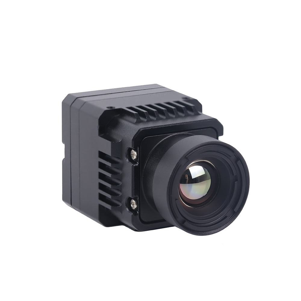
Mini 640×512 ASIC RJ45/CVBS Thermal Imaging Camera Module
to cud inżynierii zaprojektowany specjalnie do środowisk o ograniczonych parametrach SWaP. Dzięki miniaturyzacji elektroniki bez poświęcania jakości sensora dostarczamy rdzeń, który mieści się w najciaśniejszych przestrzeniach. Mini 640×512 ASIC Thermal Sensor Camera Module integrates an uncooled 640×512 VOx microbolometer array with an advanced image processing ASIC engine. Built for tethered drones, PTZ surveillance systems, and multi-sensor electro-optical turrets, this module provides dual simultaneous outputs: compressed digital IP video over RJ45 Ethernet (supporting H.264/H.265 RTSP and ONVIF Profile S) alongside a real-time analog CVBS composite feed for zero-latency pilot viewing. Its onboard ASIC handles Non-Uniformity Correction (NUC), Digital Detail Enhancement (DDE), and pseudo-color palette generation directly on the hardware.
| Rdzeń czujnika: | 640 × 512 VOx High-Resolution Microbolometer |
| Rozstaw pikseli: | 12 μm |
| Czujniki 12 μm upakowują więcej pikseli na mniejszej powierzchni, umożliwiając wyraźniejszą identyfikację małych anomalii termicznych z większych odległości. | ≤ 40 mK |
| Integrated ISP: | Hardware ASIC with DDE, 3D Noise Reduction, AGC |
| Network Connectivity: | RJ45 10/100M Auto-Negotiating Ethernet |
| Network Protocols: | RTSP, ONVIF Profile S, TCP/IP, UDP, DHCP |
| Video Compression: | H.265 / H.264 Hardware Encoding |
| Analog Output: | 1-Channel CVBS (PAL / NTSC Standard Composite) |
Architectural Trade-Off Analysis
When choosing between these two module architectures, engineering teams must evaluate where video processing should occur within their overall system design:
- ✅ Choose the MIPI CSI-2 Module: Optimal when an onboard companion computer (such as an NVIDIA Jetson Orin, Raspberry Pi CM5, or Rockchip RK3588) resides within centimeters of the sensor core. Bypassing onboard H.264 compression ASICs minimizes overall power consumption, avoids video compression artifacts, preserves raw 14-bit radiometric depth, and eliminates transport latency. This makes it the preferred configuration for closed-loop drone tracking systems, autonomous collision avoidance, and precision industrial thermography.
- ✅ Choose the RJ45 / CVBS ASIC Module: Optimal when the sensor must operate independently or transmit over extended distances. The integrated ASIC handles video compression and network encapsulation onboard, allowing the module to stream directly over Ethernet cables, slip-rings, or wireless bridge modems without requiring an external companion computer. This architecture is best suited for security perimeter pan-tilt heads, tethered observation drones, and dual EO/IR surveillance pods.
OBRAZOWANIE TERMICZNE W CZASIE RZECZYWISTYM
Często zadawane pytania (szczegółowa analiza)
What is the operational difference between an IR night-vision camera and a true uncooled thermal infrared camera module?
In contrast, a true uncooled thermal infrared camera module operates in the Long-Wave Infrared spectrum (LWIR: 8 to 14 μm) using a specialized microbolometer sensor (typically Vanadium Oxide). It does not detect reflected light; instead, it measures passive thermal radiation emitted directly by any object with a temperature above absolute zero (-273.15°C), in accordance with Planck's Radiation Law and the Stefan-Boltzmann Law. Thermal modules operate in complete darkness without requiring active light sources, penetrate environmental obscurants such as smoke, fog, and light foliage, and provide per-pixel radiometric temperature measurements.
How do I interface an OEM thermal camera module with companion computers like Raspberry Pi, NVIDIA Jetson, or PX4 flight controllers?
MIPI CSI-2 Integration (NVIDIA Jetson / Raspberry Pi CM4/CM5): Connect the module's flexible flat cable (FFC) to the carrier board's MIPI CSI-2 connector. The host operating system requires a custom Linux Device Tree Source (.dts) overlay and a Video4Linux2 (V4L2) kernel sub-device driver. This configuration establishes I2C communication for camera control registers and sets up the MIPI CSI-2 receiver to capture 14-bit linear data (typically configured as RAW14 or Y16) via Direct Memory Access (DMA). This pipeline delivers uncompressed frames straight into host RAM with minimal CPU overhead, enabling real-time processing through OpenCV, CUDA, or TensorRT pipelines.
RJ45 IP Integration: Connect the camera module to an onboard Ethernet switch or companion processor using a standard Cat5e/Cat6 cable. The integrated ASIC encodes the video stream into H.264/H.265 format. The host application accesses the feed using a GStreamer pipeline or OpenCV VideoCapture via RTSP (e.g., rtsp://192.168.1.100:554/live). This approach simplifies physical wiring across gimbal slip-rings, though it adds 80 to 180 ms of network buffering latency.
Flight Controller Integration (PX4 / ArduPilot): Thermal cores rarely connect directly to the main flight controller because microcontrollers lack the processing power needed to handle high-bandwidth video streams. Instead, wire the thermal module into an onboard companion computer. The companion processor runs target detection or temperature thresholding algorithms, then communicates with the flight controller over a UART or CAN interface using the standard MAVLink protocol. It can trigger alarms via STATUSTEXT messages or transmit target coordinates using LANDING_TARGET lub VISION_POSITION_ESTIMATE commands. If low-latency video is required for manual piloting, the module's CVBS analog output can route directly to an onboard 5.8 GHz analog video transmitter (VTX).
Why should commercial and defense UAV payloads upgrade from 256×192 or 384×288 sensors to a 640×512 resolution module?
With a 256×192 sensor, a human target located 300 meters away covers less than 2 pixels on the array. This limited coverage makes the target appear as an indistinct thermal blob, which leads to high false-positive rates and missed detections in edge AI models.
A 640×512 sensor resolves that same 300-meter target across more than 12 pixels. This provides sufficient structural detail for computer vision models (such as YOLOv8 or RT-DETR) to reliably extract distinctive features—such as head-and-shoulder geometry—dramatically reducing false alarms. Additionally, the higher pixel count allows the drone to operate at safer, higher flight altitudes while maintaining ground sampling resolution, or to scan significantly wider ground swaths per flight hour during search-and-rescue, wildlife surveys, or pipeline inspections.
How do optical materials and lens coatings affect thermal imaging performance?
Monokrystaliczny German (Ge): Germanium offers a high refractive index (~4.0) and very low optical dispersion, making it the industry standard for high-performance thermal lenses. However, it is dense, costly, and subject to thermal runaway—at temperatures exceeding 60°C to 70°C, its absorption increases rapidly, significantly reducing optical transmission.
Szkło chalkogenidkowe: An engineered amorphous material composed of selenium, sulfur, and tellurium. Chalcogenide glass is lighter and more cost-effective to produce than Germanium because it can be molded into precision aspheric lenses using hot glass pressing techniques. It also maintains optical transmission across wider temperature swings. Many modern drone lenses use hybrid optical designs, pairing a front Germanium element with internal Chalcogenide lenses to provide passive athermalization from -40°C to +80°C.
Optical Coatings: Lenses require Anti-Reflective (AR) coatings to overcome high Fresnel reflection losses (which can exceed 36% per surface on uncoated Germanium). Exterior lens elements also require Diamond-Like Carbon (DLC) hard coatings to protect against sand, rain erosion, and chemical corrosion during aerial missions.
What is the advantage of shutterless non-uniformity correction over traditional mechanical shutters in autonomous drone operations?
Eliminating Frame Drops: During calibration, the video output freezes. If the drone is executing high-speed autonomous flight, automated obstacle avoidance maneuvers, or tracking moving targets with visual servoing, this 500 ms blind spot can cause the tracking filter to lose its lock or interrupt flight navigation pipelines.
Mechanical Reliability: Solenoids and mechanical shutter blades are sensitive to sustained high-frequency motor vibrations from drone airframes. The mechanical assembly is often one of the first components to suffer mechanical wear or failure in harsh, high-vibration operational environments.
Optymalizacja SWaP-C: Shutterless modules replace physical shutter mechanisms with factory-calibrated parametric algorithms. These algorithms monitor internal temperature sensors embedded across the sensor package and continuously apply correction matrices in software. This design eliminates mechanical moving parts, reduces total payload weight, lowers power consumption, and provides an uninterrupted video stream essential for autonomous navigation and AI-driven target tracking.
📚 Piśmiennictwo i dalsze lektury
- Standard branżowy: Microbolometer manufacturing and thermal sensor production technologies by KUYANG and specialized semiconductor fabrication processes by Układ JM.
- Powiązany przewodnik: Explore our comprehensive analysis on How to Choose the Best Infrared Thermal Imaging Camera Module for Drones & Embedded Systems.
- Embedded Integration: Read our technical guide on integrating MIPI CSI-2 thermal modules with Raspberry Pi and embedded platforms.
- System Categorization: Browse our library of electro-optical sensor modules in the thermal imaging engineering directory.