Jak wybrać najlepszy moduł kamery termowizyjnej na podczerwień do dronów, Raspberry Pi i integracji Edge AI
3 lipca 2026
Najlepszy moduł kamery termowizyjnej 256x192 25mm do samodzielnie budowanych lunet i dronów: Ekonomiczny czujnik IR dalekiego zasięgu
3 lipca 2026
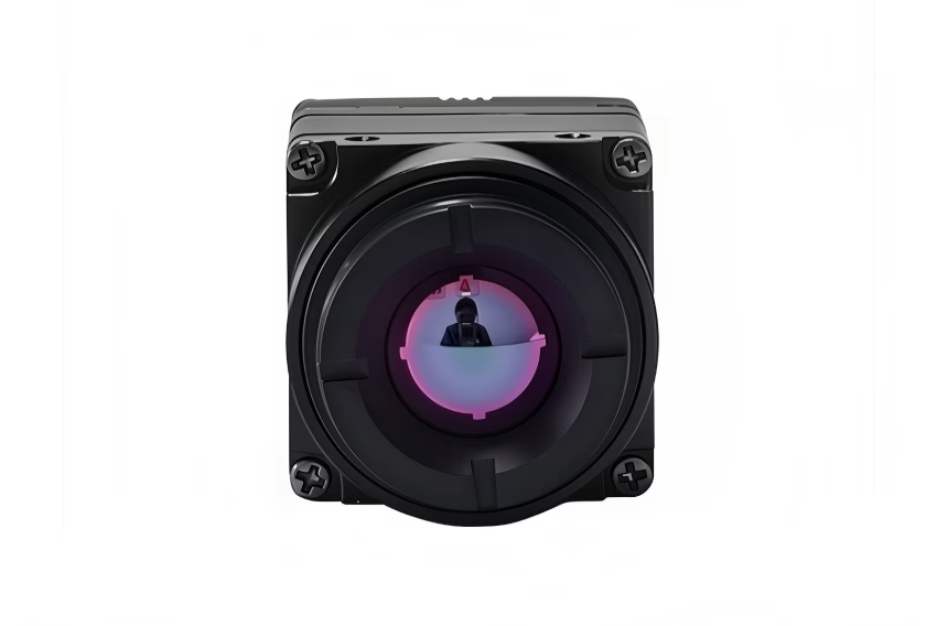
Moduł kamery termowizyjnej 640 512 35mm: Kompletny przewodnik integracji B2B dla dronów i Edge AI
Dla wykonawców z branży obrony lotniczej i kosmicznej, integratorów systemów ładunków użytecznych oraz twórców sprzętu Edge AI, wybór idealnego ładunku termowizyjnego to ćwiczenie w równoważeniu rozdzielczości przestrzennej, powiększenia optycznego i rygorystycznych ograniczeń Rozmiaru, Wagi i Mocy (SWaP). Spośród szeregu nowoczesnych konfiguracji sensorów, niechłodzony moduł długofalowej podczerwieni (LWIR) moduł kamery termowizyjnej 640 512 35mm stał się branżowym optimum dla obserwacji średniego i dalekiego zasięgu, rolnictwa precyzyjnego, inspekcji sieci energetycznych oraz taktycznych bezzałogowych systemów powietrznych (UAS). Zapewnia optymalny kompromis między odpowiednio wąskim polem widzenia (NFOV) a danymi przestrzennymi o wysokiej gęstości, bez konieczności stosowania masywnej obudowy, mocy chłodzenia i kosztów związanych z kriogenicznie chłodzonymi systemami MWIR.
Integracja tych specjalistycznych rdzeni sensorów z nowoczesnymi gimbalami dronów i potokami Edge AI wymaga głębokiego zrozumienia fizyki optycznej, interfejsów fizycznych (takich jak USB, RJ45 RTSP/IP i MIPI CSI-2) oraz potoków przetwarzania. Ten przewodnik techniczny dostarcza firmom inżynieryjnym i liderom architektury systemów dokładnych specyfikacji, matematycznych kompromisów, zasad schematów elektrycznych i interfejsów programistycznych niezbędnych do pomyślnej integracji niechłodzonych rdzeni mikrobolometrycznych 640x512 w rozwiązaniach przemysłowych nowej generacji na krawędzi sieci.
Słuchaj, w warsztacie nie traktujemy rdzeni termowizyjnych jak kamer internetowych typu plug-and-play. To precyzyjne instrumenty radiometryczne. Kiedy latasz platformą powietrzną wartą wiele tysięcy dolarów nad infrastrukturą krytyczną, zgadywanie szybko staje się kosztowne. Przeanalizujmy rzeczywistość inżynieryjną, aby te sensory działały bezproblemowo w warunkach rzeczywistych.
Spis treści
- 👉 Sekcja 1: Fizyka optyczna i przestrzenna rdzenia sensora 640x512 35mm
- 👉 Sekcja 2: Optymalizacja SWaP-C i fizyczna integracja z dronem
- 👉 Sekcja 3: Protokoły interfejsów: Wybór USB, RTSP/IP i MIPI CSI-2
- 👉 Sekcja 4: Inżynieria oprogramowania Edge AI i przetwarzanie matrycy termicznej
- 👉 Sekcja 5: Bezpośrednia macierz porównawcza komercyjnych modułów rdzeni LWIR
- 👉 Sekcja 6: FAQ dotyczące szczegółowej integracji
Fizyka optyczna i przestrzenna rdzenia sensora 640x512 35mm
Zrozumienie mechaniki niechłodzonych mikrobolometrów jest kluczowe przy ocenie wysokowydajnego moduł kamery termowizyjnej 640 512 35mm. Nowoczesne systemy niechłodzone wykorzystują próżniowo pakowaną matrycę płaszczyzny ogniskowej (FPA) składającą się z mikrorezystorów z tlenku wanadu (VOx) lub amorficznego krzemu (α-Si). Rezystory te rejestrują zmiany oporu pod wpływem promieniowania długofalowej energii podczerwonej (zazwyczaj w paśmie spektralnym 8μm do 14μm). Wydajność tych sensorów zależy od rozmiaru piksela, czułości termicznej (NETD) i parametrów układu optycznego.
Przewaga rozdzielczości przestrzennej: 640x512 vs. 384x288
Oto sedno: natywna matryca sensora 640x512 zawiera dokładnie 327 680 aktywnych pikseli. Dla porównania, bazowy sensor 384x288 daje zaledwie 110 592 piksele. Przejście na moduł termowizyjny klasy 640 zapewnia dokładny 2,96-krotny (prawie 3-krotny) wzrost surowej gęstości pikseli. Ten skok przestrzenny jest kluczowy dla misji dronów i algorytmów automatycznego rozpoznawania celów (ATR). Podczas gdy algorytmy interpolacji skalowania mogą sztucznie wygładzić klatkę 384x288, nie są w stanie wprowadzić szczegółów przestrzennych o wysokiej częstotliwości ani rozróżnić subpikselowych gradientów termicznych o wysokim kontraście — takich jak pojedynczy luźny przewód rdzenia na słupie wysokiego napięcia czy strukturalny punkt przegrzania podczas misji poszukiwawczo-ratowniczej. Natywne piksele są krytyczne dla dokładnych algorytmów konserwacji predykcyjnej i modeli śledzenia.
Pole widzenia (FOV) i matematyka projekcji przestrzennej
W przypadku zautomatyzowanych systemów detekcji, obliczenie pola widzenia i projekcji przestrzennej na ziemi jest niezbędne. Obliczmy rzeczywiste poziome i pionowe pole widzenia modułu termowizyjnego wykorzystującego matrycę 640x512 o rozmiarze piksela 12 μm, sparowaną z germanowym obiektywem o ogniskowej 35 mm.
Najpierw określ fizyczne wymiary aktywnego obszaru sensora (W_sensor i H_sensor):
W_sensor = 640 pikseli × 12 μm = 7,68 mm
H_sensor = 512 pikseli × 12 μm = 6,144 mm
Korzystając z trygonometrycznego równania ogniskowej:
FOV = 2 × arctan(d / (2 × f))
Gdzie d to aktywny wymiar sensora, a f to ogniskowa (35 mm):
HFOV = 2 × arctan(7,68 mm / 70 mm) ≈ 12,54°
VFOV = 2 × arctan(6,144 mm / 70 mm) ≈ 10,02°
To wąskie HFOV (≈ 12,5°) zachowuje się jak optyczny system teleobiektywowy. Specjalizuje się w izolowaniu przestrzennych emisji termicznych na duże odległości, rzutując regiony o wysokiej gęstości pikseli na odległe cele.
Model kryteriów Johnsona (DRI) dla obiektywu 35 mm
Kryteria Johnsona to standard branżowy używany do przewidywania prawdopodobieństwa wykrycia, rozpoznania lub identyfikacji celu przez obserwatora przy określonej konfiguracji sensora. Dla niechłodzonego sensora LWIR (rozmiar piksela 12 μm) z obiektywem 35 mm, wydajność celu jest modelowana przy użyciu krytycznego wymiaru celu wynoszącego 1,8 m (reprezentującego stojącą dorosłą osobę) i 2,3 m (dla średniej wielkości pojazdu użytkowego). Ocena tych limitów przy prawdopodobieństwie 50% (N50):
- 🎯 Detekcja (DRI-D): Wymaga 1,5 piksela na krytycznym wymiarze celu.
- 🎯 Rozpoznanie (DRI-R): Wymaga 6,0 pikseli na krytycznym wymiarze celu.
- 🎯 Identyfikacja (DRI-I): Wymaga 12,0 pikseli na krytycznym wymiarze celu.
Korzystając z tych zmiennych, inżynierowie systemowi mogą obliczać zasięgi celu z wysoką precyzją:
| Model celu | Wymiar krytyczny | Zasięg detekcji (1,5 px) | Zasięg rozpoznania (6,0 px) | Zasięg identyfikacji (12,0 px) |
|---|---|---|---|---|
| Cel ludzki | 1,8 metra | 5250 metrów | 1312 metrów | 656 metrów |
| Pojazd użytkowy | 2,3 metra | 6 708 metrów | 1 677 metrów | 838 metrów |
Wczesne określenie prawidłowych wymagań optycznych zapobiega awariom integracji systemu. Deweloperzy, którzy chcą poznać szersze techniki optymalizacji, powinni zapoznać się z naszym Przewodnikiem po modułach termicznych 2025, który obejmuje podstawową konfigurację systemu i tanie platformy deweloperskie.
Optymalizacja SWaP-C i fizyczna integracja z dronem
W przypadku wielowirnikowych i stałopłatowych bezzałogowych statków powietrznych (UAV) masa ładunku działa jako bezpośredni mnożnik wpływający na zużycie baterii, nagrzewanie silników i ogólną wytrzymałość lotu. Dlatego minimalizacja SWaP-C (rozmiar, waga, pobór mocy i koszt) pozostaje głównym celem inżynierii sprzętowej przy wyborze moduł kamery termowizyjnej 640 512 35mm.
Stabilność termiczna jest ogromnym problemem podczas projektowania ładunków do dronów. W przeciwieństwie do czujników CMOS światła widzialnego, niechłodzone mikrobolometry są niezwykle wrażliwe na wewnętrzne gradienty termiczne. Zmiany temperatury obudowy modułu mogą powodować dryft surowego sygnału czujnika, maskując rzeczywiste emisje celu obrazami duchów, wzorcami szumów lub zmianami offsetu sygnału. Aby złagodzić ten problem w projektach mechanicznych, należy pamiętać o następujących konkretnych strategiach:
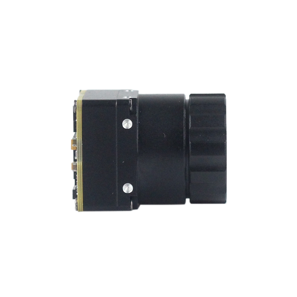
- ⚙️ Pasywne układy rozpraszania ciepła: Zamontuj miniaturowy rdzeń o wymiarach 21 mm × 21 mm bezpośrednio do strukturalnej aluminiowej ramy gimbala drona, używając wysokowydajnego materiału interfejsu termicznego (TIM). Na przykład użyj silikonowej folii fazowo-zmiennej o grubości 0,5 mm lub podkładki grafitowej o wysokiej przewodności cieplnej w płaszczyźnie (>1500 W/m·K). Zapewnia to odprowadzanie energii cieplnej z płaszczyzny ogniskowej czujnika.
- ⚙️ Kalibracja korekcji płaskiego pola (FFC): Podczas lotu chłodzenie wiatrem i ekspozycja na słońce powodują lokalne wahania temperatury obudowy. Aby to skompensować, należy zapewnić dynamiczną aktywację wewnętrznego mechanizmu migawki na podstawie czujników temperatury umieszczonych bezpośrednio na matrycy FPA i zespole obiektywu. Ta oparta na migawce korekcja niejednorodności (NUC) eliminuje dryfty czasowe i resetuje offset bazowy pikseli.
Ekranowanie przed zakłóceniami elektromagnetycznymi (EMI)
Silniki bezszczotkowe, wysokoczęstotliwościowe elektroniczne regulatory prędkości (ESC) oraz nadajniki i transceivery telemetryczne dużej mocy (takie jak łącza 900 MHz, 2,4 GHz lub 5,8 GHz) działają w ciasnych, wypełnionych szumami przestrzeniach nowoczesnych płatowców. Niekontrolowane EMI mogą objawiać się jako poziome linie skanowania, szum okresowy lub utrata synchronizacji w cyfrowych lub analogowych strumieniach wideo.
Aby zapobiec degradacji sygnału, obudowa kamery musi być elektrycznie ciągła i uziemiona bezpośrednio do wspólnej masy systemowej płyty sterującej gimbala za pomocą ultra-elastycznego mikro-koncentrycznego oplotu ekranującego lub metalowych klipsów uziemiających. Dodatkowo, zintegruj miniaturowe koraliki ferrytowe (np. seria Murata BLM) i ceramiczne kondensatory o niskim ESR (10 μF i 0,1 μF równolegle) bezpośrednio przy pinach wejściowych zasilania niestandardowego interfejsu złącza modułu, aby odfiltrować tętnienia elektryczne pochodzące z poboru wysokiego prądu przez silniki.
Mechaniczna absorpcja wstrząsów i stabilizowane mocowania gimbala
Aby zapobiec drganiom i rozmyciu obrazu przy dużych prędkościach, moduły te wymagają izolacji drgań o wysokiej częstotliwości. Zamocuj obudowę kamery w uchwycie gimbala za pomocą silikonowych pierścieni tłumiących o niskiej twardości lub aktywnych, wibroizolacyjnych tulei (zazwyczaj poliuretan o twardości 30A do 45A w skali Shore'a). Układ optyczny z obiektywem 35 mm przesuwa punkt równowagi modułu do przodu w porównaniu ze standardowymi obiektywami szerokokątnymi 9 mm. Podczas modelowania gimbala użyj oprogramowania do projektowania wspomaganego komputerowo (CAD), aby skalibrować środek ciężkości 3D na przecięciu osi pochylenia i przechyłu. Zmniejsza to ciągłe obciążenie prądowe bezszczotkowych silników serwo i zapewnia stabilny, pozbawiony drgań obraz w wietrznych warunkach operacyjnych.
Protokoły interfejsu sprzętowego: Wybór między USB a RTSP/IP a MIPI CSI-2
Zrozumienie surowego opóźnienia, wąskich gardeł przetwarzania i złożoności na poziomie pinów jest kluczowe przy wyborze interfejsu transmisyjnego do integracji B2B. Poniżej znajduje się analiza kompromisów inżynieryjnych trzech głównych interfejsów używanych przez moduł kamery termowizyjnej 640 512 35mm w nowoczesnych systemach dronów.
| Protokół interfejsu | Maksymalna przepustowość | Opóźnienie wideo | Maksymalna długość kabla | Złożoność wdrożenia B2B |
|---|---|---|---|---|
| USB 2.0 / USB-C (UVC) | 480 Mb/s | 80 - 120 ms | < 3 metry | Minimalna (standardowe sterowniki UVC) |
| RTSP / IP (RJ45) | 100 / 1000 Mb/s | 150 - 250 ms | < 100 metrów | Średnia (konfiguracja gniazd i kompresja) |
| MIPI CSI-2 | 1,5 Gb/s na linię | < 10 ms | < 15 cm | Wysoka (wymaga niestandardowych sterowników jądra) |
USB 2.0 / Type-C (implementacja klasy UVC)
Wybór modułu opartego na USB, takiego jak Miniaturowy rdzeń LWIR 640, upraszcza cykl rozwoju sprzętu. Działając jako standardowe urządzenie klasy USB Video Class (UVC), montuje się bezpośrednio jako /dev/video0 w jądrach Linux, nie wymagając własnościowych przechwytywaczy ramek wideo ani dostosowanych sterowników interfejsu. To standardowe wsparcie klasy sterowników sprawia, że jest wysoce kompatybilny z komputerami wbudowanymi, takimi jak seria NVIDIA Jetson lub platformy Raspberry Pi, umożliwiając szybkie prototypowanie oprogramowania do komercyjnych testów terenowych.
RJ45 / Strumieniowanie IP RTSP (moduły z włączonym ASIC)
W przypadku sieci infrastrukturalnych, placów maszyn przemysłowych lub struktur dronów na uwięzi analogowo-cyfrowej dalekiego zasięgu, modele ze zintegrowanymi układami ASIC zapewniają natywne, standardowe przetwarzanie oparte na IP. Stos protokołu RTSP (Real-Time Streaming Protocol) kompresuje surowe piksele termiczne do wysokowydajnych strumieni H.264/H.265 w sieci IP, umożliwiając routing na duże odległości po standardowych liniach Ethernet CAT5e/CAT6. Ta konfiguracja jest szeroko stosowana w przemysłowym monitoringu obwodowym, monitorowaniu podstacji i stałych stacjach dokowania dronów, gdzie integracja sieciowa i strumienie z wielu kamer muszą być zbieżne w scentralizowanym centrum kontroli.
Natywny MIPI CSI-2 (Mobile Industry Processor Interface)
W przypadku taktycznych mikrogimbali UAV i przestrzennego śledzenia celów, nawet 100-milisekundowe opóźnienie wideo może powodować odchylenia naprowadzania lub utratę celu podczas szybkich manewrów. Moduł czujnika termicznego MIPI CSI-2 (2-liniowy lub 4-liniowy) omija warstwy serializacji USB i pętle kodowania Ethernet, przesyłając surowe cyfrowe macierze ramek bezpośrednio do odbiornika MIPI procesora aplikacyjnego (takiego jak Nvidia Jetson Orin lub Raspberry Pi). Redukuje to całkowite wewnętrzne opóźnienie transportu do mniej niż 10 ms, co jest krytyczne dla wnioskowania Edge AI w czasie rzeczywistym, automatycznego targetowania i szybkich dynamicznych pętli stabilizacji gimbala.
Dla inżynierów oceniających surową, niestandardową konstrukcję w porównaniu z integracją gotowych modułów, zapoznaj się z naszym kompleksowym omówieniem w Przewodnik konwersji: Termowizja DIY vs. rozwiązania profesjonalne.
Inżynieria oprogramowania Edge AI i przetwarzanie matrycy termicznej
Integracja wysokorozdzielczego, dalekiego zasięgu moduł kamery termowizyjnej 640 512 35mm z platformą Edge AI, taką jak Nvidia Jetson Orin, wymaga lekkiej, wielowątkowej architektury oprogramowania. Struktura ta musi utrzymywać stałą przepustowość 30 Hz surowych ramek podczas uruchamiania algorytmów wizji komputerowej i wnioskowania modelu. Proces frameworka oprogramowania opiera się na bibliotekach takich jak OpenCV i wyspecjalizowanych modułach przechwytywania ramek do analizy obszaru zainteresowania.
Poniżej znajduje się gotowa do produkcji implementacja w Pythonie zaprojektowana dla wbudowanych procesorów brzegowych. Przechwytuje surowe strumienie termiczne, normalizuje głębię bitową do 8-bitowej skali wizualnej, stosuje proces CLAHE (Contrast Limited Adaptive Histogram Equalization) w celu rozróżnienia śladów termicznych na odległość i podświetla przegrzewające się cele termiczne:
import cv2
import numpy as np
import logging
import sys

# Configure logging for remote terminal deployment
logging.basicConfig(level=logging.INFO, format='[%(asctime)s] [%(levelname)s] %(message)s')

class ThermalAISystem:
    def __init__(self, device_index=0, frame_width=640, frame_height=512):
        self.device_index = device_index
        self.width = frame_width
        self.height = frame_height

        # Initialize OpenCV capture device using V4L2 backend
        self.cap = cv2.VideoCapture(self.device_index, cv2.CAP_V4L2)
        if not self.cap.isOpened():
            logging.error(f"Failed to bind thermal camera framegrabber to device index: /dev/video{self.device_index}")
            sys.exit(1)

        # Configure video format parameters
        self.cap.set(cv2.CAP_PROP_FRAME_WIDTH, self.width)
        self.cap.set(cv2.CAP_PROP_FRAME_HEIGHT, self.height)

        # Initialize CLAHE engine for high-frequency contrast optimization
        self.clahe_engine = cv2.createCLAHE(clipLimit=3.5, tileGridSize=(8, 8))
        logging.info(f"Thermal AISystem successfully initialized: 640x512 resolution tracking.")

    def run_pipeline(self):
        try:
            while True:
                ret, frame = self.cap.read()
                if not ret:
                    logging.warning("Failed to grab physical frame from thermal core channel.")
                    continue

                # Check for 14-bit or 16-bit raw digital arrays, fallback to standard frame
                if frame.dtype == np.uint16 or len(frame.shape) == 2:
                    # Raw radiometric values directly from sensor
                    gray_frame = frame
                else:
                    # Convert standard color channel input to grayscale representation
                    gray_frame = cv2.cvtColor(frame, cv2.COLOR_BGR2GRAY)

                # Ensure the frame resolution meets specification targets
                if gray_frame.shape[0] != self.height or gray_frame.shape[1] != self.width:
                    gray_frame = cv2.resize(gray_frame, (self.width, self.height), interpolation=cv2.INTER_LINEAR)

                # Normalize raw 12-bit/14-bit sensor array values into standard 8-bit dynamic range
                normalized_frame = cv2.normalize(gray_frame, None, 0, 255, cv2.NORM_MINMAX, dtype=cv2.CV_8U)

                # Apply CLAHE to resolve far-field structures
                contrast_enhanced = self.clahe_engine.apply(normalized_frame)

                # Apply high-contrast pseudo-coloring (Jet or Inferno)
                colored_render = cv2.applyColorMap(contrast_enhanced, cv2.COLORMAP_JET)

                # Establish warning threshold values for hot spot tracking
                _, threshold_mask = cv2.threshold(contrast_enhanced, 230, 255, cv2.THRESH_BINARY)

                # Segment targets using contour extraction
                contours, _ = cv2.findContours(threshold_mask, cv2.RETR_EXTERNAL, cv2.CHAIN_APPROX_SIMPLE)

                # Extract target coordinates and overlay analytics
                for contour in contours:
                    if cv2.contourArea(contour) > 15:  # Filter out sub-pixel sensor noise
                        x, y, w, h = cv2.boundingRect(contour)
                        # Draw bounding box over target zones
                        cv2.rectangle(colored_render, (x, y), (x+w, y+h), (0, 0, 255), 2)
                        cv2.putText(colored_render, "OVERHEATING TARGET DETECTED", (x, y - 10),
                                    cv2.FONT_HERSHEY_SIMPLEX, 0.4, (0, 0, 255), 1)

                # Render analytical output stream to screen
                cv2.imshow("Industrial Thermal Core Feed", colored_render)

                # Terminate execution loop safely on 'q' press
                if cv2.waitKey(1) & 0xFF == ord('q'):
                    break

        except KeyboardInterrupt:
            logging.info("Thermal processing pipeline terminated manually.")
        finally:
            self.cap.release()
            cv2.destroyAllWindows()
            logging.info("Hardware framework released safely.")

if __name__ == "__main__":
    system = ThermalAISystem(device_index=0)
    system.run_pipeline()
Tabela porównawcza komercyjna i strukturalna głównych modułów
Poniższe profile zintegrowanych produktów reprezentują standardowe w branży niechłodzone silniki czujników mikrobolometrycznych obecnie w produkcji. Każda jednostka wykorzystuje zaawansowane układy scalone odczytu (ROIC), aby zapewnić wysoką rozdzielczość przestrzenną i solidną odporność środowiskową.

Niekolowana miniaturowa kamera termowizyjna LWIR USB 640*512, moduł rdzenia do dronów, podobna do DJI
Ten ultra-kompaktowy niechłodzony moduł rdzenia LWIR charakteryzuje się niezwykle małą obudową o wymiarach zaledwie 21 mm * 21 mm. Zaprojektowany do głębokiej integracji z systemami fizycznymi w ograniczonych wagowo gimbalach UAV i kadłubach wielowirnikowców, zapewnia wyjątkowo ostre obrazowanie termiczne o wysokim kontraście przy minimalnych kosztach sprzętowych.
Wyposażony w szerokie wsparcie dla wielu obiektywów (z konfiguracjami obiektywów 5/9/13/18/35/50/75/100/150 mm), jest wyjątkowo wszechstronną platformą rozwojową. Działając natywnie w rozdzielczości wyjściowej 640*512 (lub opcjonalnie 640*480), moduł ten jest wysoce adaptowalny do ekstremalnych środowisk, zapewniając stałą niezawodność kalibracji w aktywnych warunkach lotu.

Niechłodzony moduł kamery termowizyjnej z sensorem 640*512, RJ45, CVBS, RTSP, IP
Zaprojektowany do profesjonalnych zastosowań w sieciach przemysłowych, ten zintegrowany niechłodzony miniaturowy moduł podczerwieni 640*512 posiada wbudowany potok ASIC zoptymalizowany pod kątem bezpośredniej transmisji danych opartej na IP. Obsługuje natywne strumieniowanie sieciowe RJ45, fizyczne wyjście wideo analogowego CVBS oraz standardowe strumienie wideo RTSP.
Ta architektura sprzętowa umożliwia zdalną konfigurację sieci i strumieniowanie, eliminując potrzebę stosowania zewnętrznego, wysoko wydajnego procesora aplikacyjnego na brzegu sieci. Jest idealna do stacjonarnego monitorowania obwodowego, automatyzacji ciężkich zakładów przemysłowych oraz przewodowych wojskowych systemów obserwacji powietrznej.
FAQ dotyczące szczegółowej integracji
Dlaczego warto wybrać natywny moduł termiczny 640x512 35 mm zamiast rozdzielczości 384x288 lub skalowanych w górę?
Wybór natywnego czujnika 640x512 zamiast rdzenia o niższej rozdzielczości zapewnia krytyczny wzrost wydajności, którego nie można odtworzyć za pomocą interpolacji programowej. Matryca 384x288 daje 110 592 przestrzennych punktów pomiarowych na płaszczyźnie ogniskowej. W kontraście, natywna matryca 640x512 daje 327 680 punktów — dokładnie 2,96 razy więcej surowych danych pikselowych. W połączeniu z obiektywem 35 mm fizyczny rozstaw pikseli (zazwyczaj 12 μm) określa częstotliwość próbkowania przestrzennego czujnika.
Użycie obiektywu 35 mm zawęża poziome pole widzenia do 12,5°, koncentrując aktywne piksele na odległych celach. Ta konstrukcja optyczna pozwala modułowi działać na pełnym limicie dyfrakcyjnym, rozróżniając anomalie termiczne o wysokiej częstotliwości (takie jak luźne zaciski dystrybucyjne lub podpowierzchniowe defekty infrastruktury), które ramki 384x288 skalowane programowo by wygładziły. Interpolacja programowa nie może wstrzyknąć surowych danych fizycznych; dlatego natywne piksele są niezbędne do dokładnego, niezawodnego automatycznego rozpoznawania celów (ATR) i modeli konserwacji predykcyjnej.
Jak przesyłać strumieniowo wideo termiczne w czasie rzeczywistym z niskim opóźnieniem z tego modułu do Raspberry Pi lub niestandardowego systemu wbudowanego?
Aby przesyłać strumieniowo wideo w czasie rzeczywistym z niskim opóźnieniem z modułu kamery termicznej 640 512 35 mm do systemu wbudowanego, programiści muszą zoptymalizować ścieżkę danych sprzęt-program. Standardowe sterowniki Linux używają wielobuforowej kolejki (V4L2_BUFF_TYPE_VIDEO_CAPTURE), która może wprowadzać do 100 ms opóźnienia z powodu warstw abstrakcji intensywnie przetwarzających. Aby wyeliminować to wąskie gardło, skonfiguruj silnik przechwytywania wideo tak, aby używał podwójnego buforowania (przydzielając dokładnie 2 bufory ramek) i pobierał ramki za pomocą bezpośredniego dostępu do pamięci (DMA).
Dodatkowo, użyj dedykowanego wątku przechwytującego klatki, działającego z natywną częstotliwością odświeżania sensora (np. 30 Hz lub 60 Hz), aby stale aktualizować bufor wymiany klatek w pamięci systemowej. Twoje główne pętle wnioskowania Edge AI lub renderowania wideo mogą następnie asynchronicznie odpytywać ten współdzielony bufor. Dzięki temu wątek przechwytywania kamery pozostaje nieblokowany i zapobiega gromadzeniu się klatek w pamięci RAM systemu, co skutkuje ultraniskimi opóźnieniami przesyłania strumieniowego (często poniżej 20 ms przez natywną magistralę MIPI CSI-2 lub zoptymalizowaną magistralę USB).
Czy ten 35-milimetrowy rdzeń termiczny jest wystarczająco lekki do kompaktowych gimbali dronów?
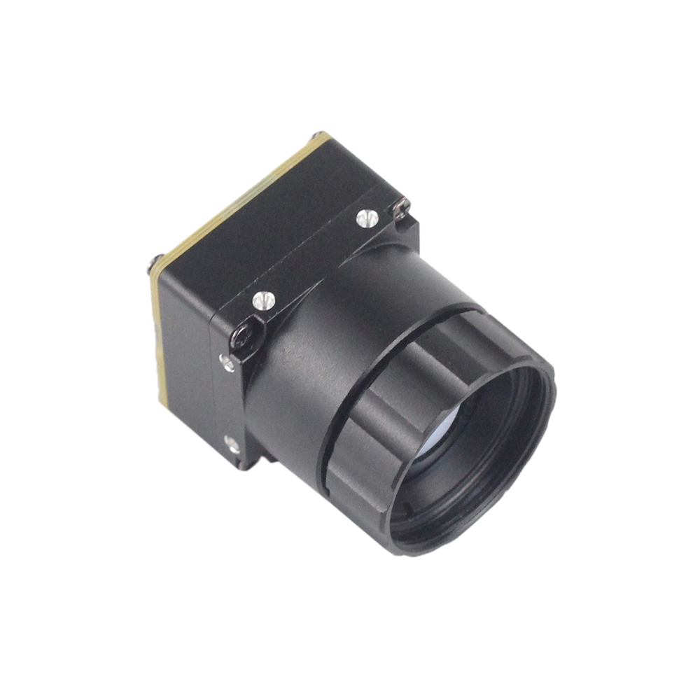
Tak, niechłodzone moduły kamer termicznych 640x512 są projektowane specjalnie z myślą o spełnieniu rygorystycznych wymagań SWaP (rozmiar, waga i moc) małych gimbali dronów. Układ PCB rdzenia jest wysoce kompaktowy, mierzy zaledwie 21 mm × 21 mm i waży tylko kilka gramów. Głównym składnikiem wagi jest wyspecjalizowany 35-milimetrowy układ soczewek germanowych, co daje całkowitą wagę zespołu od około 45 do 85 gramów, w zależności od wytrzymałego stylu obudowy i fizycznego otworu przysłony.
Ponieważ 35-milimetrowa soczewka germanowa dalekiego zasięgu przesuwa środek ciężkości do przodu, unikaj montowania kamery płasko względem płyty osi pochylenia. Zamiast tego użyj szczelinowych uchwytów montażowych kamery, aby precyzyjnie ustawić pozycję kamery wzdłuż jej fizycznej osi podłużnej. Wyważenie powinno być kalibrowane przy użyciu modelowania CAD i walidowane na statycznym stanowisku gimbala. Zapewnienie prawidłowego wyważenia na osiach pochylenia i przechyłu minimalizuje prądy trzymania, zapobiega przegrzewaniu się silników i wydłuża czas lotu systemów dronów.
📚 Referencje i dalsza lektura
- Standard branżowy: Wizja komputerowa i surowe operacje macierzowe obsługiwane przez Biblioteka OpenCV Core SDK
- Standard branżowy: Wysokowydajne wsparcie sprzętowe wbudowane od Arducam Embedded Imaging
- Powiązany przewodnik: Kompleksowy przewodnik programisty na Modele szybkiej integracji niskokosztowego modułu termicznego 2025 dla inżynierów
- Powiązany przewodnik: Techniczne spostrzeżenia na temat niestandardowego sprzętu w jak budować profesjonalne rozwiązania termowizyjne