Moduł kamery termowizyjnej USB o wysokiej rozdzielczości dla Raspberry Pi: Przewodnik integracji 640x512
1 lipca 2026
Moduł kamery noktowizyjnej True IR: Przewodnik integracji B2B
1 lipca 2026
Kompletny przewodnik po integracji modułu kamery termowizyjnej: Rozwiązania 384x288 dla dronów, Raspberry Pi i projektów OEM B2B
W szybko rozwijającym się krajobrazie automatyki przemysłowej, bezzałogowych statków powietrznych (UAV) i wizji komputerowej wdrażanej na krawędzi, wymóg obrazowania termowizyjnego o wysokiej rozdzielczości przesunął się ze specjalistycznego luksusu do fundamentalnej konieczności architektonicznej. Integracja modułu kamery termowizyjnej z nowoczesnymi systemami wbudowanymi wymaga czegoś więcej niż standardowego, gotowego sprzętu hobbystycznego. Inżynierowie systemowi, dyrektorzy ds. badań i rozwoju oraz menedżerowie produktów OEM stają przed złożonymi przeszkodami, w tym ścisłymi ograniczeniami wagowymi (SWaP), integralnością sygnału o wysokiej częstotliwości i obciążeniem inżynieryjnym związanym z ekstrakcją surowych danych radiometrycznych. Bądźmy szczerzy: historycznie rurociągi projektowe utykały z powodu sztywnych, zamkniętych rdzeni kamer konsumenckich lub słabego wsparcia SDK, które nie potrafiło zasypać przepaści między niestandardowymi interfejsami sprzętowymi a standardowymi wbudowanymi systemami operacyjnymi, takimi jak Linux czy ROS.
Aby pokonać te bariery, przemysłowe niechłodzone rdzenie LWIR (długofalowej podczerwieni) o rozdzielczości 384x288 pikseli wyłoniły się jako branżowy złoty środek. Równoważąc czułość termiczną, wagę i zasięg optyczny, te 12μm rdzenie mikrobolometryczne zapewniają ponad dwukrotnie większą aktywną powierzchnię sensora niż podstawowe sensory 256x192, bez wykładniczego wzrostu kosztów i rozmiarów rdzeni klasy VGA. Ten kompleksowy przewodnik szczegółowo opisuje techniczne, elektryczne i optyczne aspekty integracji wysokowydajnych modułów kamer termowizyjnych 384x288 z dronami, niestandardowymi systemami Raspberry Pi i własnym sprzętem IoT, poparte najnowocześniejszymi praktykami inżynieryjnymi liderów rynku.
Spis treści
- 👉 Przegląd architektoniczny inżynierii sensorów LWIR
- 👉 Demistyfikacja hierarchii rozdzielczości: Rdzenie 384x288 vs. 256x192
- 👉 Architektury interfejsów elektrycznych: MIPI, USB i CVBS
- 👉 Plan integracji systemów Raspberry Pi i Linux
- 👉 Inżynieria ładunku gimbala drona i optymalizacja SWaP-C
- 👉 Prezentacja produktu: Moduł termowizyjny Purpleriver 384x288
- 👉 Przemysłowe ścieżki dostosowywania OEM/ODM
- 👉 Integracja sprzętowa i FAQ wdrożeniowe
Przegląd architektoniczny inżynierii sensorów LWIR
Oto sedno: pod maską każdej rzeczywistej kamery termowizyjnej znajduje się niechłodzona matryca sensora mikrobolometrycznego zaprojektowana do wykrywania promieniowania w spektrum długofalowej podczerwieni (LWIR), zazwyczaj w zakresie od 8μm do 14μm. W przeciwieństwie do krzemowych sensorów CMOS światła widzialnego, które polegają na generowaniu ładunku indukowanego fotonami, niechłodzone termopile lub mikrobolometry wykorzystują materiały, których opór elektryczny zmienia się dynamicznie w miarę pochłaniania padającego promieniowania podczerwonego. W warsztacie przysięgamy na Tlenek wanadu (VOx) cienkie warstwy jako aktywny materiał czujnikowy. Dlaczego? Ponieważ oferują wyjątkowy Temperaturowy Współczynnik Rezystancji (TCR) i utrzymują szum 1/f na absolutnym minimum w porównaniu do tańszych alternatyw z amorficznego krzemu (a-Si).
Łańcuch przetwarzania w nowoczesnym niechłodzonym rdzeniu termicznym rozpoczyna się, gdy padające promieniowanie LWIR przechodzi przez zespół soczewek germanowych o wysokiej czystości. Soczewki te nie są standardowym szkłem — są pokryte specjalistycznymi warstwami antyrefleksyjnymi (AR), aby zmaksymalizować wydajność transmisji w pasmach podczerwieni. Gdy ukierunkowana energia podczerwieni trafi na matrycę ogniskową (FPA) składającą się z matrycy mikrobolometrów VOx, poszczególne elementy pikseli ulegają niewielkiej zmianie temperatury. To przemieszczenie termiczne powoduje zmianę oporu elektrycznego w każdej indywidualnej strukturze mikromostka. Wbudowany układ odczytu (ROIC) następnie przekształca te minimalne wahania oporu na 14-bitowe lub 16-bitowe surowe sygnały cyfrowe za pomocą szybkiego wewnętrznego przetwornika analogowo-cyfrowego (ADC). Na koniec wbudowany procesor sygnałowy (DSP) lub dedykowany układ FPGA wykonuje złożone procedury kalibracyjne, takie jak korekcja niejednorodności (NUC), zastępowanie uszkodzonych pikseli (BPR) i mapowanie radiometryczne, generując wysoce stabilny, niskoszumowy strumień termiczny.
Rola rozmiaru piksela (12 μm vs. 17 μm)
Wydajność termodynamiczna czujnika termicznego jest częściowo determinowana przez jego rozmiar piksela — fizyczną odległość od środka jednego elementu piksela do środka następnego. Przejście ze starszych matryc 17 μm na nowoczesne konstrukcje o rozmiarze piksela 12 μm to nie tylko drobna poprawka; to całkowita zmiana reguł gry w elektrooptyce przemysłowej:
- ✅ Wydajność optyczna: Mniejszy rozmiar piksela pozwala na umieszczenie matrycy 384x288 na znacznie mniejszej fizycznej strukturze czujnika. Zmniejsza to całkowitą powierzchnię czujnika i umożliwia architektom systemów stosowanie mniejszych, lżejszych i bardziej opłacalnych elementów optycznych z germanu, aby osiągnąć identyczne pole widzenia (FOV). Oznacza to oszczędność wagi bez utraty widoku.
- ✅ Stała czasowa termiczna: Przy mniejszych indywidualnych objętościach pikseli masa termiczna każdego mostka VOx jest radykalnie zmniejszona. Pozwala to pikselowi szybciej reagować na przejściowe zmiany temperatury, co skutkuje zmniejszonym opóźnieniem termicznym i rozmyciem ruchu podczas szybkiego skanowania lub lotu drona.
Czułość termiczna (NETD)
Równoważna temperatura szumowa (NETD) jest głównym wskaźnikiem oceniającym czułość modułu kamery termicznej. Wyrażona w milikelwinach (mK), NETD określa minimalną różnicę temperatur, jaką czujnik może rozróżnić od poziomu szumu tła. Moduły klasy przemysłowej wykazują NETD ≤ 40 mK lub ≤ 50 mK przy $f/1.0$. Oznacza to, że czujnik może z łatwością wykrywać różnice temperatur tak małe, jak 0,04°C. Osiągnięcie tak niskich wartości NETD wymaga precyzyjnych parametrów kalibracyjnych realizowanych przez sprzęt wbudowany, w tym algorytmów korekcji niejednorodności w czasie rzeczywistym (NUC) i zastępowania uszkodzonych pikseli.
Demistyfikacja hierarchii rozdzielczości: Rdzenie 384x288 vs. 256x192
Podczas projektowania wbudowanego systemu termicznego w terenie inżynierowie muszą wybierać między różnymi rozdzielczościami czujników. Podczas gdy podstawowe rdzenie 256x192 — takie jak tanie amatorskie klucze USB lub kompaktowe konsumenckie czujniki termiczne — są na papierze wysoce opłacalne, zawodzą w krytycznych zastosowaniach przemysłowych, komercyjnych i obronnych. Wybór niechłodzonego modułu kamery termicznej 384x288 zapewnia ogromne korzyści operacyjne:
Przewaga gęstości informacji
Spójrzmy na matematykę. Czujnik 384x288 daje dokładnie 110 592 dyskretnych pikseli danych termicznych. Dla kontrastu, czujnik 256x192 daje tylko 49 152 piksele. Przejście na konfigurację 384x288 zapewnia 125% wzrost całkowitej rozdzielczości danych aktywnych. Ta masywna ekspansja danych przestrzennych zapobiega błędom uśredniania subpikselowego, umożliwiając modelom sztucznej inteligencji brzegowej (Edge AI) izolowanie konturów celów znacznie wcześniej i z większą dokładnością. Wyższa gęstość pikseli pozwala również na bardziej precyzyjne pomiary temperatury, ponieważ kamera jest mniej podatna na agregowanie temperatury małego celu z chłodniejszym otoczeniem.
Rozdzielczość przestrzenna i chwilowe pole widzenia (iFOV)
Wskaźnik iFOV mierzy rozdzielczość przestrzenną pojedynczego piksela, definiując najmniejszy obszar celu, który może być rozróżniony z określonej odległości. Matematycznie iFOV wyraża się jako:
Jeśli przeanalizujemy stałą soczewkę germanową o ogniskowej 19 mm sparowaną z mikrobolometrem 12 μm:
W odległości 100 metrów każdy piksel rozróżnia fizyczny rozmiar plamki wynoszący około 6,3 cm. W krytycznych zastosowaniach bezpieczeństwa, systemach wizji maszynowej lub badaniach lotniczych ta zwiększona rozdzielczość przestrzenna zapewnia dokładną identyfikację celów, zapobiegając niebezpiecznym fałszywym alarmom. Aby uzyskać głębszą analizę wyboru docelowych zespołów optycznych LWIR, zapoznaj się z tym wyczerpującym przewodnikiem wyboru rdzenia LWIR dla przemysłu.
Architektury interfejsów elektrycznych: MIPI, USB i CVBS
Aby pomyślnie zintegrować moduł kamery termowizyjnej z niestandardowym sprzętem, należy wybrać odpowiednią warstwę komunikacji sprzętowej. Przemysłowe moduły kamer termowizyjnych 384x288 oferują trzy główne interfejsy elektryczne, każdy dostosowany do odrębnych wymagań inżynieryjnych:
| Typ interfejsu | Głębokość danych i typ sygnału | Najlepiej nadaje się do | Narzut sprzętowy |
|---|---|---|---|
| MIPI CSI-2 | 14-bitowe surowe dane cyfrowe, ścieżka o wysokiej przepustowości | Wbudowane układy SOC (NVIDIA Jetson, Rockchip) | Wysoki (Wymaga niestandardowych sterowników jądra/BSP) |
| USB (UVC + Bulk) | Dynamiczne wideo kolorowe i surowe macierze radiometryczne | Raspberry Pi, komputery przemysłowe, szybkie prototypowanie | Niski (Standardowe stosy sterowników plug-and-play) |
| CVBS | Standardowe analogowe wideo kompozytowe (PAL/NTSC) | Analogowe systemy FPV, starsze monitory analogowe | Minimalny (Bezpośrednie okablowanie do nadajnika/monitora) |
MIPI CSI-2 (Interfejs procesora przemysłu mobilnego)
MIPI CSI-2 stał się złotym standardem dla połączeń kamer o wysokiej przepustowości, bezpośrednio do procesora. Przesyła nieskompresowane, surowe cyfrowe dane termiczne o wysokiej głębi bitowej (zazwyczaj 14-bitowe lub 16-bitowe) bezpośrednio do potoku przechwytywania wideo hostowego systemu na chipie (SoC). Pozwala to procesorowi hosta na dostęp do surowych wartości czujnika bez opóźnień dekompresji czy narzutu translacji protokołu, otwierając możliwości sprzętowo przyspieszonego przetwarzania sygnału obrazu (ISP) przy użyciu wyspecjalizowanych modułów GPU lub NPU.
Chociaż MIPI CSI-2 oferuje najniższe możliwe opóźnienie klatki i maksymalną wydajność systemu, wymaga złożonych, niestandardowych konfiguracji sterowników pakietu wsparcia płytki (BSP). Z doświadczenia powiem: prowadzenie różnicowych linii wysokiej częstotliwości na niestandardowych płytkach PCB wymaga starannego dopasowania długości, aby zapobiec zniekształceniom fazowym i EMI. Utrzymuj te przebiegi kablowe poniżej 10 cm, chyba że lubisz debugować problemy z integralnością sygnału za pomocą aktywnych, dedykowanych przedłużaczy sygnału.
Interfejs USB (UVC i punkty końcowe Bulk)
Interfejs Universal Serial Bus (USB) jest preferowany do szybkiego rozwoju na komputerach jednopłytkowych (SBC) i ogólnych stacjach roboczych deweloperskich. Ten interfejs wykorzystuje podejście rozwidlone: strumieniuje wstępnie przetworzone, pokolorowane strumienie wideo termicznego przy użyciu standardowego protokołu USB Video Class (UVC), jednocześnie udostępniając surowe 14-bitowe macierze temperatur radiometrycznych przez niestandardowe punkty końcowe przesyłu zbiorczego USB.
Główną zaletą podejścia USB jest fizyczna prostota plug-and-play. Większość nowoczesnych systemów operacyjnych (Linux, Windows, macOS) jest dostarczana z natywnymi sterownikami UVC, eliminując potrzebę kompilowania niestandardowych modułów jądra. Należy jednak pamiętać, że systemy te wykazują wyższe opóźnienia w porównaniu do bezpośrednich potoków MIPI, a zarządzanie transferami danych zbiorczych o wysokiej przepustowości może wprowadzać znaczne obciążenie procesora na hostowych mikrokontrolerach o niskim poborze mocy.
CVBS (Sygnał wideo pasma podstawowego kompozytowego)
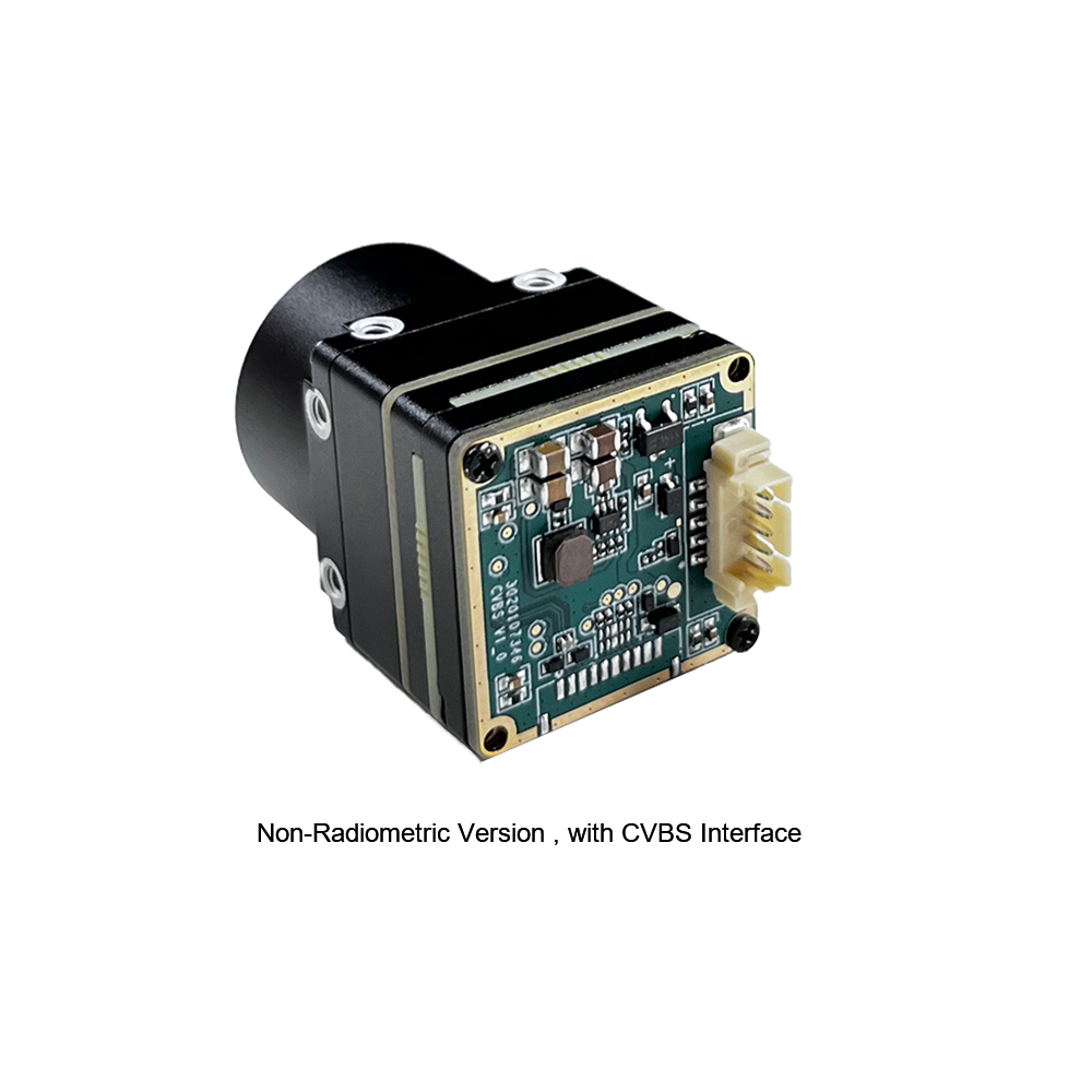
CVBS to analogowy format transmisji telewizyjnej o standardowej rozdzielczości (NTSC lub PAL) szeroko stosowany w starszych systemach. Wbudowany procesor obrazu modułu termicznego rekonstruuje zdigitalizowane odczyty termiczne, mapuje je na wybieraną przez użytkownika paletę kolorów i przekształca wynikowy strumień wizualny w przebieg analogowy. To wyjście może być przesyłane bezpośrednio przez linie koncentryczne lub wysokomocowe analogowe łącza wideo RF.
CVBS charakteryzuje się wyjątkowo niskim opóźnieniem, wysoką odpornością na fizyczne zakłócenia elektromagnetyczne oraz zdolnością do pracy na długich przebiegach kablowych (do 100 metrów) bez zaników sygnału. Głównym ograniczeniem jest zawartość danych: ponieważ sygnał jest ściśle analogowym wideo, wszystkie surowe metadane pikseli termodynamicznych są tracone, co uniemożliwia wykonywanie obliczeń temperatury w post-processingu na sprzęcie odbiorczym.
Plan integracji systemów Raspberry Pi i Linux
Integracja wysokowydajnego rdzenia kamery termowizyjnej z komputerem jednopłytkowym, takim jak Raspberry Pi (4/5) lub modułem NVIDIA Jetson, umożliwia szybkie prototypowanie inteligentnych kamer IoT, klasyfikatorów termicznych edge AI oraz przenośnego oprzyrządowania testowego. Rzeczywista implementacja w dużym stopniu opiera się na solidnych wzorcach pozyskiwania danych, które łączą akwizycję w przestrzeni jądra z aplikacjami przetwarzającymi w przestrzeni użytkownika.
Architektura systemu rozpoczyna się na poziomie jądra Linux, gdzie fizyczny rdzeń jest rozpoznawany za pośrednictwem standardowych sterowników USB UVC lub szeregowych. Sterownik mapuje przychodzące ramki do rdzenia Virtual Video for Linux (V4L2), udostępniając je aplikacjom w przestrzeni użytkownika poprzez /dev/videoX interfejs węzła urządzenia. Ścieżki sterowania, aktualizacje konfiguracji i ładunki mikrokomend są jednocześnie kierowane przez wirtualny interfejs szeregowy (taki jak /dev/ttyUSBX), zarządzany przez stan operacyjny aplikacji hosta.
Nawigacja w potoku oprogramowania
Aby przechwytywać i przetwarzać strumień termiczny bez utraty ramek lub blokowania kolejki systemowej, aplikacje deweloperskie mogą wykorzystywać wysoce wydajne potoki oprogramowania. Korzystając z frameworka narzędzi systemowych, takiego jak GStreamer, deweloperzy mogą strukturyzować sieci przechwytywania o niskim narzucie, które kierują surowe bufory ramek YUYV lub surowe 16-bitowe w skali szarości (Y16) do wątków przetwarzania OpenCV z minimalnym opóźnieniem:
gst-launch-1.0 -v v4l2src device=/dev/video0 ! video/x-raw,format=Y16,width=384,height=288 ! videoconvert ! appsink
To polecenie przechwytuje surowy 16-bitowy strumień termiczny, omija złożone procesy konwersji kolorów na poziomie sterownika i przekazuje surowe jednostki pikseli. Aplikacja może następnie analizować, manipulować i koloryzować ramki programowo.
Ekstrakcja danych radiometrycznych i komunikacja SDK
W celu dokładnej diagnostyki termograficznej aplikacje muszą być w stanie konwertować surowe dane pikseli na bezwzględne wartości temperatury. Poniższy potok integracji w Pythonie demonstruje, jak przechwytywać surowe ramki za pomocą OpenCV, ekstrahować 14-bitowe liczby cyfrowe, stosować fabryczne parametry kalibracyjne i wizualizować przetworzone dane wyjściowe w czasie rzeczywistym:
import cv2
Inżynieria ładunku gimbala drona i optymalizacja SWaP-C
Wdrażanie kamer termowizyjnych na małych bezzałogowych statkach powietrznych (sUAS) wymaga ścisłego przestrzegania ograniczeń dotyczących rozmiaru, wagi, mocy i kosztów (SWaP-C). Dodanie masy bezpośrednio wpływa na czas pracy baterii, podczas gdy zakłócenia elektromagnetyczne mogą zagrażać stabilności lotu.
Projekt elektryczny zaczyna się od czystej dystrybucji zasilania. Niestabilizowane zasilanie z magistrali statku powietrznego (zazwyczaj 12 V do 24 V z wieloogniwowych baterii LiPo) jest wysoce podatne na tętnienia napięcia o wysokiej częstotliwości generowane przez elektroniczne regulatory prędkości (ESC) i szybkoobrotowe bezszczotkowe silniki prądu stałego (BLDC). Bez odpowiedniej filtracji ten szum elektryczny może pogorszyć wydajność wysoce czułych matryc termograficznych, objawiając się jako pasmowanie obrazu lub szum na wyjściu termicznym.
Aby temu zapobiec, zawsze kierujemy przychodzące linie prądu stałego przez specjalistyczny, wysokotłumiący filtr dolnoprzepustowy (taki jak sieć filtrów LC) przed podaniem napięcia na dedykowany liniowy regulator napięcia o niskim spadku (LDO). Ten regulator obniża napięcie do czystego zasilania 3,3 V lub 5 V DC, utrzymując wysoki współczynnik tłumienia tętnień zasilania (PSRR), aby chronić delikatne matryce czujników lub pokładowe jednostki przetwarzające przed szumami z linii zasilającej.
Przewodnik po mechanicznej i środowiskowej izolacji drona
- ⚙️ Tłumienie drgań i mikrofonowanie: Wysokoczęstotliwościowe impulsy kinetyczne z szybko obracających się śmigieł mogą powodować wibracje mechaniczne, które zniekształcają odczyty mikrobolometru. Aby złagodzić ten szum mikrofonowy, zamocuj rdzeń kamery do ramy gimbala za pomocą silikonowo-żelowych tłumików drgań o niskiej twardości, chroniąc niechłodzony czujnik przed szumem mikrowibracji.
- ⚙️ Ekranowanie elektromagnetyczne (EMI): Moduły telemetrii RF dużej mocy i nadajniki wideo zamontowane blisko kamer termowizyjnych mogą indukować szum wzorcowy na matrycy niechłodzonego czujnika. Pełne umieszczenie modułu kamery termowizyjnej w przemysłowej obudowie aluminiowej obrabianej CNC zapewnia ochronę mechaniczną i działa jak klatka Faradaya przed EMI.
- ⚙️ Ochrona środowiskowa i kalibracja: Ładunki lotnicze są narażone na gwałtowne zmiany temperatury i wilgotności podczas szybkich wznoszeń i opadów. Należy upewnić się, że system radzi sobie z gorącymi i zimnymi warunkami bez utraty ostrości optycznej, a także wdrożyć automatyczne algorytmy NUC oparte na migawce lub sterowane programowo, aby utrzymać dokładność przy zmiennych temperaturach otoczenia. Więcej na ten temat można znaleźć w tym diagnostycznym spojrzeniu na testy środowiskowe kamer termowizyjnych.
Prezentacja produktu: Moduł termowizyjny Purpleriver 384x288
Purpleriver projektuje i produkuje wysokowydajne niechłodzone rdzenie kamer termowizyjnych dalekiej podczerwieni. Ich systemy łączą niechłodzone elementy czujników mikrobolometrycznych z solidnymi ... potokami przetwarzania sygnału obrazu. To czyni je idealnymi do komercyjnych zastosowań, takich jak inspekcje bezpieczeństwa, laboratoria badawcze i wbudowane ładunki dronów.
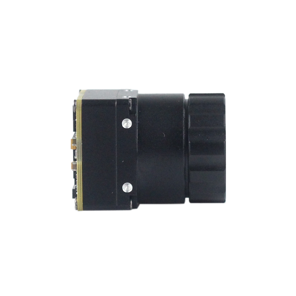
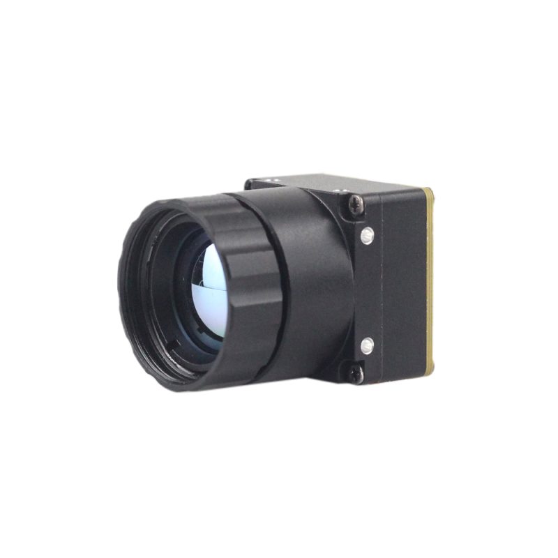
Niechłodzony Moduł Kamery Termicznej na Podczerwień Serii MD 384x288
Moduł kamery termowizyjnej Purpleriver został zaprojektowany z myślą o przemysłowej precyzji w zastosowaniach takich jak bezpieczeństwo, monitorowanie temperatury i integracja z dronami. Wyposażony w niechłodzony detektor podczerwieni o rozstawie pikseli 12 μm, zapewnia wysoką czułość i ostre obrazowanie termiczne. Jego kompaktowe rozmiary, funkcjonalność plug-and-play oraz wiele interfejsów (MIPI/USB/CVBS) gwarantują wszechstronną i szybką integrację z różnymi systemami. Wspierany przez zespół z doświadczeniem z Hongkońskiego Uniwersytetu Nauki i Technologii oraz byłych ekspertów Huawei Hisilicon, moduł ten oferuje dostosowanie OEM/ODM do specyficznych wymagań projektowych, zapewniając niezrównaną wydajność i adaptowalność.
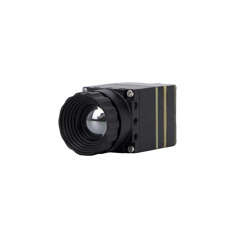
Niechłodzona miniaturowa kamera termowizyjna 384*288 do dronów
Moduł termowizyjnego pomiaru temperatury serii MINI to wysokoprecyzyjny, małogabarytowy i uniwersalny termowizor do pomiaru temperatury online. Wykorzystuje wysokiej jakości detektory, wysoką rozdzielczość, stabilną wydajność i zaawansowane funkcje. Jest wyposażony w wiele interfejsów, co czyni go preferowanym produktem w takich dziedzinach zastosowań, jak wizja maszynowa, inspekcje bezpieczeństwa, inteligentna produkcja, konserwacja sprzętu, systemy pokładowe robotów i dronów i tym podobne.
Porównawcza macierz specyfikacji
Aby pomóc projektantom systemów w wyborze odpowiedniego rdzenia sprzętowego do ich projektów, poniżej porównano fizyczne, elektryczne i optyczne charakterystyki operacyjne serii MD i serii MINI:
| Parametry techniczne | Moduł serii MD 384x288 | Niechłodzony rdzeń drona MINI 384x288 |
|---|---|---|
| Rozdzielczość (układ FPA) | 384 x 288 Pikseli | 384 x 288 Pikseli |
| Rozmiar piksela | Struktura mikrobolometru 12 μm | Struktura mikrobolometru 12 μm |
| Zakres spektralny | 8 μm do 14 μm (LWIR) | 8 μm do 14 μm (LWIR) |
| Czułość (NETD) | ≤ 40 mK (@25°C, f/1.0) | ≤ 50 mK (@25°C, f/1,0) |
| Dostępne interfejsy | MIPI CSI-2, USB 2.0 (UVC), analogowe CVBS | USB 2.0 (UVC), analogowe wideo CVBS |
| Funkcjonalność termograficzna | Zaawansowana regionalna analiza radiometryczna | Pomiar temperatury w czasie rzeczywistym |
| Typowy pobór mocy | Ekstremalnie niski (< 1,1 W) | Zoptymalizowany niski pobór mocy (< 0,9 W) |
| Docelowe dostosowania | Doskonałe (głębokie, niestandardowe projekty OEM B2B) | Adaptacja ładunku użytecznego i integracje z gimbalami |
Przemysłowe ścieżki dostosowywania OEM/ODM
Gotowe konsumenckie kamery termowizyjne rzadko nadają się do złożonych zastosowań przemysłowych. Specjalistyczne konstrukcje wymagają dostosowanych konfiguracji fizycznych, niestandardowych układów soczewek i unikalnych protokołów komunikacyjnych.
Proces dostosowywania rozpoczyna się podczas wstępnego definiowania wymagań, gdzie menedżerowie produktu ustalają granice operacyjne elektryczne, fizyczne i atmosferyczne. Po ustaleniu tych parametrów inżynierowie tłumaczą standardowe zestawy poleceń modułu na protokoły systemów przemysłowych (takie jak formaty SPI, Modbus lub CAN Bus). Ta warstwa protokołu umożliwia rejestrom konfiguracyjnym kamery bezproblemową komunikację ze sterownikami PLC, inteligentnymi węzłami motoryzacyjnymi lub kontrolerami lotu na krawędzi. Równocześnie inżynierowie pracują nad optymalizacją komponentów optycznych i czynników ochronnych, aby zapewnić stabilną wydajność termiczną w trudnych warunkach wdrożeniowych.
Dostosowanie protokołu (SPI, Modbus, CAN Bus)
Nowoczesne architektury przemysłowe i wojskowe opierają się na wysoce niezawodnych protokołach komunikacyjnych. Podczas gdy USB jest odpowiednie do podstawowych testów laboratoryjnych, integracje terenowe wymagają czystszych architektur magistrali:
- ⚙️ Magistrala CAN (Controller Area Network): Niezbędny w sterowaniu systemami motoryzacyjnymi, lotniczymi i robotycznymi. Umożliwia komunikację na duże odległości, odporną na błędy, między różnymi węzłami bez konieczności scentralizowanej architektury host-PC.
- ⚙️ Protokół Modbus: Standard dla programowalnych sterowników logicznych (PLC) w zakładach produkcyjnych. Ten interfejs umożliwia kamerze wyzwalanie alarmów lub sterowanie wyłączeniami, gdy komponent przekroczy zdefiniowany próg temperatury.
- ⚙️ Niskomocowy SPI (Szeregowy Interfejs Peryferyjny): Idealny dla mikrokontrolerów i procesorów brzegowych. SPI umożliwia szybki transfer danych przez niestandardowe płyty nośne, minimalizując jednocześnie złożoność i zużycie energii.
Optymalizacja środowiskowa i wytrzymałe powłoki ochronne
Wdrażanie czujników w ekstremalnych przemysłowych komorach termicznych lub operacjach morskich wymaga wzmocnionej ochrony systemu:
- ⚙️ Powłoki optyczne DLC (węgiel diamentopodobny): Chroni zewnętrzne soczewki germanowe przed ściernym piaskiem, brudem i narażeniem chemicznym, zapewniając długoterminową przeżywalność w terenie.
- ⚙️ Konforemne powłoki izolacyjne PCB: Chronią wrażliwe komponenty płyty przed wilgocią, kondensacją, mgłą solną i atmosferą korozyjną.
- ⚙️ Automatyczna kalibracja migawki: Integruje solidne cele kalibracyjne, które umożliwiają rdzeniowi kamery utrzymanie dokładności pomiaru w szerokim zakresie zmian temperatury roboczej (od -40°C do +80°C).
Aby zoptymalizować wydajność w tych trudnych warunkach, producenci B2B regularnie pozyskują zaawansowane zespoły optyczne od wyspecjalizowanych partnerów precyzyjnych, takich jak Optyka wznosząca, aby zapewnić dokładne możliwości ogniskowania dwuspektralnego. Aby dowiedzieć się więcej o ogólnych przemysłowych i zewnętrznych przenośnych konstrukcjach termicznych, zapoznaj się z tym przewodnikiem na temat narzędzi do obrazowania termicznego.
Integracja sprzętowa i FAQ wdrożeniowe
Jak przesyłać strumieniowo wysokiej rozdzielczości obraz termiczny w czasie rzeczywistym do Raspberry Pi lub systemu Linux?
Integrację strumienia w czasie rzeczywistym z architekturami Raspberry Pi lub ogólnymi x86/ARM Linux można osiągnąć, wykorzystując kompleksowe zestawy SDK (Software Development Kits) firmy Purpleriver wraz ze standardowymi frameworkami systemu operacyjnego. W przeciwieństwie do standardowych platform czujników konsumenckich, które nie udostępniają kodu open-source i są zamknięte w zastrzeżonych frameworkach aplikacji, moduły Purpleriver oferują wysoce wszechstronną architekturę otwartego systemu.
W celu najbardziej niezawodnej integracji zalecamy wykorzystanie cyfrowego potoku wyjściowego USB-UVC. W tej konfiguracji system operacyjny Linux rozpoznaje strukturę dual-port kamery. Strukturyzuje to strumień wideo jako standardowe surowe wyjście YUV na głównym /dev/videoX kanale, jednocześnie utrzymując surowe łącze komend/radiometryczne przez /dev/ttyUSBX lub wirtualne interfejsy COM. Dzięki tej ścieżce konfiguracji programiści mogą uruchamiać nasze zoptymalizowane polecenia przechwytywania GStreamer bezpośrednio z potoków przestrzeni pamięci lub odczytywać surowe macierze za pomocą kodów integracyjnych Python i OpenCV bez utraty pakietów ramek. Jeśli Twój projekt ma ścisłe ograniczenia przestrzenne lub układu, skonsultuj się z naszym zespołem w sprawie niestandardowych powiązań device-tree MIPI CSI dla niestandardowych projektów nośników.
W przypadku integracji DIY i komercyjnej, dlaczego powinienem zmodernizować czujnik 256x192 do niechłodzonego modułu kamery termowizyjnej 384x288?
Przejście z podstawowego czujnika 256x192 (takiego jak amatorska seria Tiny1) na przemysłowy niechłodzony moduł kamery termowizyjnej 384x288 z rozstawem pikseli 12 μm zapewnia ogromny skok wydajności przetwarzania przestrzennego. Podczas gdy czujnik 256x192 może być wystarczający do podstawowych kontroli termicznych, jego niska gęstość pikseli ogranicza skuteczność na większych odległościach.
Modernizacja rozdzielczości do 384x288 dostarcza ponad dwukrotnie więcej punktów danych przestrzennych (110 592 w porównaniu z 49 152 pikselami). Ma to kilka głównych praktycznych korzyści: Po pierwsze, zwiększona gęstość czujnika zapewnia ostrość i zasięg potrzebne w krytycznych operacjach, takich jak mapowanie dronami, monitorowanie bezpieczeństwa i zautomatyzowana produkcja. Po drugie, ulepszona rozdzielczość przestrzenna (iFOV) pozwala rozróżniać małe cele na znacznie większych odległościach, zapobiegając utracie dokładności spowodowanej mieszaniem temperatur poniżej piksela. Po trzecie, modele brzegowej AI mogą szybciej wykrywać i klasyfikować obiekty z mniejszą liczbą fałszywych alarmów, zapewniając niezawodne działanie w wymagających środowiskach. Dodatkowo, nasze zaawansowane mikrobolometry z czujnikiem VOx 12 μm optymalizują wydajność przestrzenną bez zwiększania fizycznego rozmiaru obiektywu. Dzięki temu Twoje systemy pozostają lekkie, kompaktowe i wysoce wydajne.
Czy te moduły kamer termowizyjnych nadają się do niestandardowych ładunków wrażliwych na wagę, takich jak gimbale dronów i celowniki termowizyjne?
Tak, rdzenie termowizyjne serii MINI firmy Purpleriver są zaprojektowane specjalnie do zastosowań wrażliwych na wagę. Nasz sprzęt i oprogramowanie układowe są zoptymalizowane, aby zapewnić maksymalną wydajność w ramach ścisłych limitów wagowych, co czyni je idealnymi do wielospektralnych gimbali dronów, kompaktowych ręcznych celowników termowizyjnych i miniaturowej optyki wojskowej/przemysłowej.
Nasz główny zespół projektowy wykorzystuje swoje bogate doświadczenie badawczo-rozwojowe z Hongkońskiego Uniwersytetu Nauki i Technologii oraz byłej inżynierii platformy krzemowej Huawei Hisilicon, aby optymalizować każdy projekt. Te optymalizacje są wbudowane w każdy rdzeń, w tym mikroskopijny format, niskie zużycie energii (poniżej 0,9 W w układach mini) oraz pełne opcje dostosowywania OEM/ODM. Aby zintegrować najlepsze rozwiązania mikrochipowe z naszymi modułami kamer, architekci systemów często współpracują z głównymi firmami półprzewodnikowymi, takimi jak Układ JM do projektowania niestandardowych, energooszczędnych węzłów przetwarzania brzegowego i inteligentnych płyt towarzyszących.
📚 Piśmiennictwo i dalsze lektury
- Standard branżowy: JM Chip Technologie Półprzewodnikowe
- Standard branżowy: Rising Optics Inżynieria Precyzyjnych Soczewek
- Powiązany przewodnik: Przewodnik po Modułach Kamer Termowizyjnych: Wybór Odpowiedniego Rdzenia LWIR
- Powiązany przewodnik: Operacje Testów Środowiskowych w Wysokiej i Niskiej Temperaturze oraz Wilgotności
- Powiązany przewodnik: Rewolucja Widzenia Cieplnego: Niezbędne Optyczne Narzędzia Termiczne