Лучший тепловизионный модуль камеры 256x192 25 мм для самодельных прицелов и дронов: экономичный длиннофокусный ИК-датчик
3 июля 2026 г.
640x512 VOx Тепловизионный модуль камеры: Полное руководство по Edge AI, дронам и прямой трансляции
6 июля 2026 г.
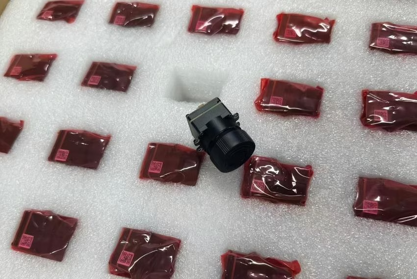
90-мм Тепловизионный модуль камеры с Edge AI: Высокоточное наблюдение на большом расстоянии
В дальнем оптическом мониторинге, промышленном наблюдении и полезных нагрузках БПЛА оборонного назначения критически важна высокая разрешающая способность при захвате целей на больших расстояниях. Стандартные широкоугольные объективы не обеспечивают пространственное разрешение на дальности до цели ($IFOV$), необходимое для уверенной идентификации за пределами нескольких сотен метров. Интеграция модуля тепловизионной камеры 90 мм устраняет этот эксплуатационный пробел. Сочетая высокоточный неохлаждаемый микроболометр с шагом пикселя 17 мкм или 12 мкм и 90-мм длиннофокусную германиевую линзовую сборку, системные архитекторы могут достичь узких полей зрения (FOV), оптимизированных для наблюдения на километровых дальностях. При расширении аппаратно-ускоренным периферийным ИИ эти модули преобразуют необработанные данные длинноволнового инфракрасного диапазона (LWIR) в полезную информацию непосредственно на периферии, снижая задержку и устраняя огромные накладные расходы на пропускную способность при потоковой передаче необработанных тепловизионных видеоданных по беспроводным каналам связи.
Инженерным группам, интегрирующим инфракрасные технологии в специальные тактические прицелы, высотные дроновые платформы или системы охраны периметра, требуется больше, чем готовые компоненты потребительского класса. В этом обзоре анализируются структурные, оптические и радиометрические требования к 90-мм тепловизионным ядрам LWIR. Мы исследуем, как чувствительность на уровне пикселя, измеряемая через эквивалентную шуму разность температур (NETD), взаимодействует с профилями оптического пропускания для определения истинной максимальной дальности действия в условиях реального атмосферного ослабления. Благодаря детальному архитектурному анализу, руководствам по аппаратной интеграции и сравнительным обзорам продуктов, это техническое руководство служит окончательным справочником для развертывания профессиональных интеллектуальных полезных нагрузок LWIR.
Суть в следующем: если вы создаете системы, предназначенные для работы в нестабильных реальных условиях, вы не можете полагаться на теоретические идеальные показатели. Вам необходимо проектировать с учетом наихудшего атмосферного рассеивания и максимизировать свои оптические преимущества с самого начала. В мастерской мы называем это проектированием под тепловую реальность, а не под технический паспорт.

Содержание
- 👉 Оптическая физика и коэффициенты пространственного разрешения
- 👉 Архитектуры интеграции электронного оборудования
- 👉 Использование периферийного ИИ: логический вывод в реальном времени на сенсоре
- 👉 Сравнительный обзор промышленных модулей ядра LWIR
- 👉 Интеграционные структуры: БПЛА, тактические прицелы и автономная робототехника
- 👉 Углубленные часто задаваемые вопросы
Оптическая физика и коэффициенты пространственного разрешения
1 Фокусное расстояние объектива и расчеты IFOV
Основная функция 90-мм объектива с фокусным расстоянием в паре с длинноволновым инфракрасным (LWIR) Википедия Микроболометр заключается в ограничении мгновенного поля зрения ($IFOV$), тем самым максимизируя пространственное разрешение на длинных траекториях до цели. $IFOV$, представляющий собой угловую проекцию одного детекторного элемента (пикселя) в пространство объекта, является фундаментальной метрикой. Математически он формулируется как:
$$МГНОВЕННОЕ ПОЛЕ ЗРЕНИЯ = \frac{p}{f}$$
где $p$ — физический шаг пикселя сенсорной матрицы (обычно 12 мкм или 17 мкм для стандартных промышленных ядер), а $f$ — эффективное фокусное расстояние оптической сборки (90 мм).
Для 12-мкм сенсорного ядра, интегрированного с 90-мм объективом:
$$IFOV_{12\mu m} = \frac{12 \times 10^{-6}\text{ м}}{90 \times 10^{-3}\text{ м}} \approx 0.133\text{ мрад}$$
И наоборот, для устаревшего 17-мкм сенсора:
$$IFOV_{17\mu m} = \frac{17 \times 10^{-6}\text{ м}}{90 \times 10^{-3}\text{ м}} \approx 0.189\text{ мрад}$$
Послушайте, уменьшение шага пикселя с 17 мкм до 12 мкм дает 6% уменьшение углового размера пикселя. Это напрямую приводит к более плотной частоте дискретизации целей на расстоянии. В практических полевых условиях пространственное разрешение на дистанции 1000 метров ($S_{1000}$) рассчитывается по формуле:
$$S_{1000} = 1000\text{ м} \times IFOV$$
Вот как это выглядит с точки зрения физического охвата:
- ✅ 12 мкм сенсор с 90-мм объективом: $S_{1000} \approx 0.133\text{ м} = 13.3\text{ см}$ физический охват на пиксель. Это обеспечивает невероятно плотную пространственную дискретизацию.
- ✅ 17 мкм сенсор с 90-мм объективом: $S_{1000} \approx 0.189\text{ м} = 18.9\text{ см}$ физический охват на пиксель. Все еще пригоден для использования, но уступает в четкости определения границ по сравнению с 12 мкм системой.
При планировании конфигураций для дальнего обнаружения, сопровождения и идентификации пространственная плотность на цели регулируется критериями Джонсона. Для стандартного обнаружения цели (1.5 пикселя на критический размер) человеческая цель (моделируемая с критической шириной 0.75 м) должна охватывать не менее 1.5 пикселя.
С 12 мкм, 90-мм основной системой максимальная дальность обнаружения ($R_{det}$) человеческой цели в идеальных условиях атмосферного пропускания динамически выводится через:
$$R_{det} = \frac{\text{Критический размер цели}}{IFOV \times \text{Требуемое количество пикселей}} = \frac{0.75\text{ м}}{0.133 \times 10^{-3}\text{ рад} \times 1.5} \approx 3,759\text{ метров}$$
Такая высокая пространственная плотность делает матрицу с фокусным расстоянием 90 мм критически важным инструментом для охраны периметра и поисково-спасательных систем. Более подробную информацию о выборе сенсоров можно найти в нашем полном руководстве по модулям тепловизионных сенсоров.
2 Характеристики MTF в спектре 8-14 мкм
Функция передачи модуляции (MTF) определяет способность системы передавать контраст от оптической сцены на поверхность детектора при различных пространственных частотах, измеряемых в парах линий на миллиметр ($\text{lp}/{\text{mm}}$). Поскольку LWIR-излучение работает в спектральных диапазонах $8\ \mu\text{м} \le \lambda \le 14\ \mu\text{м}$, дифракционно-ограниченная пространственная частота среза значительно ниже, чем у оптики видимого света, и определяется по формуле:
$$\xi_{cutoff} = \frac{1}{\lambda \cdot F\#}$$
При работе с $F/1.25$ и средней длиной волны $\lambda = 10\ \mu\text{м}$ абсолютный термодинамический предел оптической передаточной функции составляет:
$$\xi_{cutoff} = \frac{1}{10 \times 10^{-3}\text{ мм} \times 1.25} = 80\text{ lp/мм}$$
Стандартные 90-мм германиевые линзовые сборки, сконфигурированные для систем с двойным полем зрения или непрерывным зумом, используют просветляющие (AR) и твердые углеродные/алмазоподобные покрытия (DLC) для защиты от воздействия окружающей среды и минимизации внутренних френелевских отражений.
Для поддержания производительности MTF на уровне системы выше $35\%$ контраста на частоте Найквиста 12 мкм микроболометра ($\approx 41.6\text{ lp/мм}$) оптическая сборка должна изначально корректировать сферические, хроматические и астигматические аберрации в своем многоэлементном германиевом стеке. Некачественно спроектированные линзы снижают оптическую MTF ниже предела Найквиста сенсора, вызывая пространственное наложение спектров и снижая эффективную тепловую чувствительность интегрированной системы камеры.
Архитектуры интеграции электронного оборудования
1 Нативная маршрутизация моста параллельной CMOS шины к MIPI CSI-2/USB 3.0
На физическом кремниевом уровне необработанный цифровой поток с неохлаждаемого микроболометра представляет собой высокоскоростную параллельную КМОП-шину с низким напряжением (часто 14-битные необработанные цифровые данные в паре с управляющими стробами: тактовым сигналом пикселя `PCLK`, сигналом достоверности строки `LVAL` и сигналом достоверности кадра `FVAL`). Высокопроизводительные тепловизионные ядра преобразуют эту параллельную шину локально в современные высокоплотные последовательные топологии соединений, такие как MIPI CSI-2 или интерфейсы USB 3.0/Type-C, для поддержки высокого динамического диапазона и высокоскоростной передачи данных.
При трассировке этих дифференциальных сигналов на многослойной несущей плате инженеры должны точно задавать целевые импедансы в соответствии со следующими строгими физическими топологиями:
- ⚙️ Дифференциальные пары MIPI CSI-2: Должны поддерживать постоянный дифференциальный импеданс $100\ Ом$ ($\pm 10\%$) для предотвращения проблем с высокочастотными отражениями при передаче на линиях тактового сигнала и данных.
- ⚙️ USB 3.0 SuperSpeed (TX/RX): Требует трассировки с дифференциальным импедансом $90\ Ом$.
- ⚙️ Опорные слои земли: Run unbroken ground planes directly beneath all high-speed routes to isolate digital noise from the sensitive analog frontend of the bolometer.
Additionally, intra-pair skew must be limited to $<0.15\text{ mm}$ via symmetric trace routing and length snake-matching to prevent signal phase shifts on high-speed transitions. Developers can learn more about high-integrity board layups in our LWIR micro thermal camera module integration guide.
For integration with automated positioning platforms and multi-sensor stabilization gimbals, Shenzhen ChiYi Electronics Co., Ltd. provides specialized, low-latency interface converters. These components bridge industrial LWIR parallel buses to digital video outputs like HD-SDI, LVDS, or HDMI, preserving signal integrity across extended harness routings.
2.2 SDK-level interfaces for Embedded SBCs
To ingest raw 14-bit radiometric datasets into a single-board computer (SBC) like a Raspberry Pi 4/5, NVIDIA Jetson Orin Nano, or custom ARM/FPGA processing blocks, developers need to leverage the thermal core SDK. The integration pipeline executes over standard interface buses, extracting the payload directly to raw memory buffers. The process begins by instantiating raw UVC stream listeners using a backend like `libuvc` or standard kernel interfaces:
#include <iostream>
#include <libuvc/libuvc.h>

// Callback signature for processing incoming raw LWIR frames
void frame_callback(uvc_frame_t *frame, void *ptr) {
    if (frame->data_format != UVC_FRAME_FORMAT_Y16) {
        std::cerr << "Error: Incoming frame format is not 16-bit Raw Radiometric." << std::endl;
        return;
    }

    // Cast the payload data pointer to unsigned 16-bit array
    uint16_t *raw_data = static_cast<uint16_t*>(frame->data);
    int width = frame->width;
    int height = frame->height;

    // Read central frame pixel for core temperature monitoring
    int center_pixel_index = (height / 2) * width + (width / 2);
    uint16_t raw_val = raw_data[center_pixel_index];

    // Convert Kelvin hundredths representation to Celsius:
    // Temp (K) = Raw_Val / 100.0f -> Celsius = Temp (K) - 273.15f
    float temperature_celsius = (static_cast<float>(raw_val) / 100.0f) - 273.15f;

    std::printf("Center Pixel Raw: %u | Temperature: %.2f °C\n", raw_val, temperature_celsius);
}
This raw pipeline bypasses standard video encoders, preserving target temperature calculations down to $\pm 2^\circ\text{C}$ or $2\%$ accuracy per pixel location.
Использование периферийного ИИ: логический вывод в реальном времени на сенсоре
3.1 FPGA and NPU hardware acceleration layers
On-sensor core processing relies on an FPGA/ASIC coprocessor running parallelized pipelines for real-time spatial correction, Non-Uniformity Correction (NUC), and Bad Pixel Replacement (BPR). Applying these correction arrays before deep neural network inference prevents dead pixels and column drift from causing false positives in target detection.
For models running Yolov8 or MobileNet-SSD targets on local Edge NPUs, the 14-bit analytical radiometric stream is parallel-processed. One branch scales the thermal dynamic range using an adaptive histogram projection algorithm down to an INT8 tensor space suitable for neural network layers. The quantization phase maps microkelvin variance to robust physical features, enabling autonomous systems to identify personnel, structures, and machinery in low-visibility or highly congested environments.
To explore native AI accelerators inside compact LWIR setups, see our Edge AI enhanced LWIR module integration guide.
3.2 Temperature Measurement & Radiometric Data Structures
True radiometric monitoring systems output raw pixel data that corresponds directly to actual physical temperature values. Each pixel value represents a highly calibrated sensor capture of the radiant energy emitted by the target object. To maintain reading accuracy across varying ambient conditions, the internal calibration algorithm calculates compensation factors based on key physical properties. In practice, our workflow uses these parameters:
- ⚙️ Target Emissivity ($E$): Dictates the emission efficiency of the target material's surface (calibrated from 0.01 to 1.00).
- ⚙️ Atmospheric Distance ($D$): Compensates for path attenuation losses along the 90mm optical line-of-sight.
- ⚙️ Ambient Temperature ($T_{amb}$): Compensates for reflected ambient radiation entering the optical path.
These variables are adjusted dynamically in software via the SDK control registry. Writing updated values to the registers adapts the internal radiometric calculation based on the distance to the target and the local atmospheric conditions.
Сравнительный обзор промышленных модулей ядра LWIR
To guide procurement and engineering teams, the detailed comparison below lists the technical parameters of currently available uncooled LWIR core systems, categorized by pixel density, output formats, and range capabilities.
4.1 Direct product parameters & datasheet matching
| Model Specifications | Uncooled LWIR Mini 256*192 Core | Uncooled LWIR USB Mini 640*512 Core |
|---|---|---|
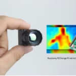
| Product Target Image | 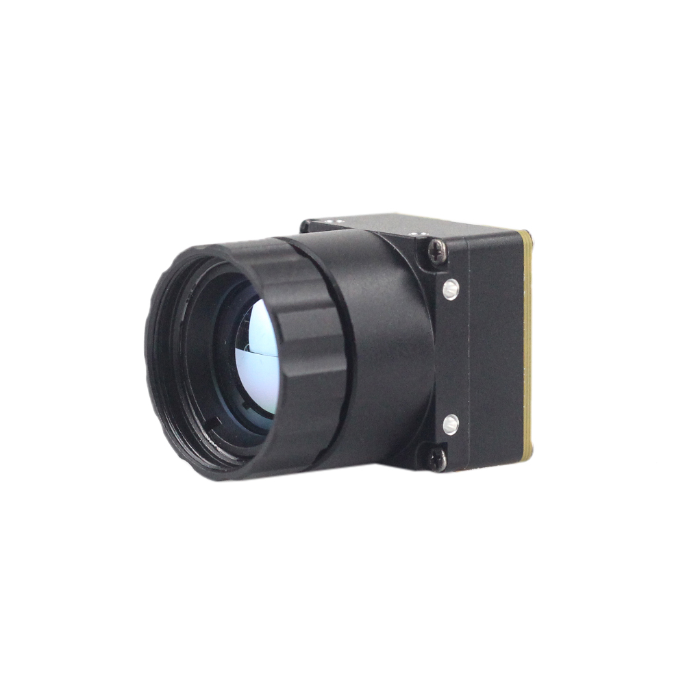 |
 |
| Detector Resolution | 256 x 192 (Ultra-Compact Form Factor) | 640 x 512 / 640 x 480 (High-Resolution Core) |
| Шаг пикселя | 12 µm | 12 µm |
| Спектральный диапазон | 8 µm to 14 µm (LWIR) | 8 µm to 14 µm (LWIR) |
| Тепловая чувствительность (NETD) | ≤ 50 mK (Ultra-clear thermal output) | ≤ 40 mK (Sharp and crisp image presentation) |
| Available Lenses (Focal Length) | Integrated wide/mid fixed lenses | 5 / 9 / 13 / 18 / 35 / 50 / 75 / 100 / 150mm configurations |
| Weight & Dimensions | Ultra-lightweight miniature design | 21mm x 21mm base mini-size, ultra-low cost |
| Primary Applications | Detecting mines, compact UAVs, local temperature mapping | Long-range drones, perimeter tracking, thermal sights |
Showcasing: Uncooled LWIR Mini 256*192 Thermal Imaging Camera Module Similar To DJI For Detecting Mines
The Mini 256 Uncooled LWIR thermal Camera Module adopts high-performance infrared detectors for ultra-clear thermal imaging and accurate temperature measurement. It captures infrared radiation and outputs a uniform thermal image with radiometry. This brings micro-class accuracy to search-and-rescue, micro UAV deployment, and specialized structural hazard mitigation missions.
Its lightweight structure makes it ideal for close-range and medium-range remote sensing work where every gram counts. Offering clean integration on single-board computers, it delivers raw temperature fields directly over modern digital buses.
Посмотреть детали и цены продукта ➔
Showcasing: Uncooled LWIR USB Mini 640*512 Thermal Imaging Camera Core Module For Drones Similar To DJI
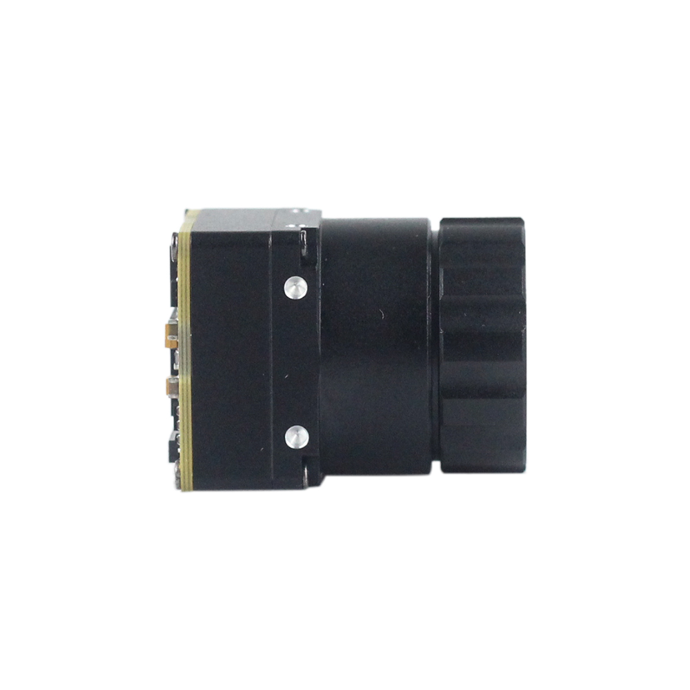
Design teams requiring clean performance over long detection channels rely on high-resolution setups. The Mini uncooled infrared thermal imaging module features in sharp and crisp image presentation, compact size and low cost. Featuring a mini-size of 21mm*21mm, and with lens focal lengths spanning 5/9/13/18/35/50/75/100/150mm and 640*480 resolution optional, it ensures stable performance and strong environmental adaptability.
When used with telephoto and zoom configurations up to 90mm or 150mm, it delivers clear physical signatures of targets several kilometers away. This level of resolution is crucial for automated perimeter defense, critical infrastructure protection, and drone-based search operations.
Посмотреть детали и цены продукта ➔
Интеграционные структуры: БПЛА, тактические прицелы и автономная робототехника
Implementing robust thermal imaging capabilities within real-world payloads requires careful balancing of mechanical, thermal, and optical considerations to protect the core-level electronics.
5.1 Drone payload SWaP considerations
For Size, Weight, and Power (SWaP) constraints on unmanned aerial vehicles (UAVs), integrating a 90mm focal length lens introduces a weight offset that shifts the sensor's center of gravity forward.
- ✅ Weight Offset: A 90mm telephoto germanium lens can weigh between $180\text{ g}$ and $350\text{ g}$, compared to a lightweight $15\text{ g}$ ultra-microbolometer core.
- ✅ Gimbal Balancing: Placing the core-sensor assembly behind a heavy lens shift moves the target balance forward. The physical center of gravity on custom dual-axis brushless gimbals must be manually trim-balanced along the pitch axes. This ensures the gimbal motors don't overheat or degrade control loop integrity during high-frequency wind corrections.
Peak motor torque requirements ($T_m$) are calculated based on predicted wind loads and operational angular accelerations:
$$T_m = I_{axis} \cdot \alpha_{target}$$
where $I_{axis}$ is the combined moment of inertia of the 90mm lens and core structure, and $\alpha_{target}$ is the targeted angular response speed. Ensuring the gimbal system has adequate holding torque prevents tracking slippage in turbulent flight conditions.
Additionally, a 90mm core-system drawing up to $1.5\text{W}$ at peak performance (typically during automated calibration shutter cycles) must be powered via shielded DC-DC buck step-down converters. This prevents high-frequency electromagnetic interference (EMI) from degrading the UAV's GPS, compass, and telemetry communications.
5.2 Scope & Weapon-Sight ruggedized optomechanics
To deploy 90mm uncooled thermal assemblies in tactical sighting systems, the mountings and internal electronics must withstand high, sudden mechanical forces:
- ⚙️ Shock & Vibe Isolation: Sighting assemblies can experience impulse accelerations exceeding $1,000\text{ G}$ over sub-millisecond durations during recoil. Sensor cores must be shock-isolated within the main CNC-milled chassis using structural fluoro-silicone dampers. This protects both the ceramic microbolometer package glass seal and the optical sub-assembly.
- ⚙️ Atmospheric & Environmental Sealing: Sighting scopes must maintain an inert internal environment across rapid temperature and pressure changes. Housings should be nitrogen-purged and sealed with dual Viton O-rings to an IP67 rating. This prevents moisture from condensing on the internal optical surfaces of the germanium lens elements.
- ⚙️ Thermal Isolation & Uniformity: Changes in barrel temperature can transfer heat to the scope enclosure, creating internal thermal gradients. Isolating the infrared core from the mounting rings using Delrin or G10 fiberglass thermal isolation rings helps maintain spatial temperature uniformity across the detector array. This minimizes calibration drift and ensures accurate target detection over extended operations.
Углубленные часто задаваемые вопросы
Can I stream real-time, high-resolution thermal data from a 90mm module to a Raspberry Pi or Arduino?
In contrast, 8-bit or 32-bit microcontrollers like Arduino Uno, ESP32, or STM32 lack the memory bus bandwidth and processing capacity required for real-time high-resolution video streams. A $640\times512$ frame at 16 bits per pixel requires $655,360\text{ bytes}$ of physical RAM per frame buffer, which exceeds the entire RAM capacity of standard microcontrollers. For lightweight microcontroller integrations, a downsampled low-rate SPI or serial telemetry stream can be used to capture raw temperature readings at lower frame rates (typically $\le 2\text{ fps}$). Alternatively, high-performance applications should leverage dedicated embedded processors to stream full-frame, high-resolution thermal video.
How does a 90mm thermal imaging module perform for custom DIY scopes, UAV integration, and vehicle-mounted projects?
$$HFOV = 2 \cdot \arctan\left(\frac{640 \times 12 \times 10^{-6}\text{ m}}{2 \times 90 \times 10^{-3}\text{ m}}\right) \approx 4.88^\circ$$
This narrow field of view concentrates the spatial resolution of the sensor over a highly focused area, enabling long-range target classification at distances that standard wide-angle cores (e.g., 9mm or 13mm models) cannot resolve. For drone and vehicle mounts, this high optical magnification allows operators to maintain a safe standoff distance while capturing clear, detailed thermal images. However, the narrower field of view also increases sensitivity to mechanical vibrations. Integrating these systems on moving platforms typically requires active stabilization, such as a high-frequency brushless gimbal, or electronic image stabilization (EIS) algorithms on custom tactical scopes to maintain a steady image and prevent target tracking loss.
Why choose a professional Edge AI thermal core over a salvaged automotive or cheap DIY sensor?
With a professional Edge AI thermal core, developers gain access to comprehensive SDKs, open firmware standards, API configurations, and calibrated radiometric data ($Kelvin = LSB / 100$) directly over standard digital connections. Modern cores also feature on-board hardware accelerators for intelligence pipelines, allowing developers to execute tracking, object detection, and temperature-anomaly triggering directly on the core without needing heavy external processing assemblies.
📚 References & Further Reading
- Отраслевой стандарт: Википедия Микроболометр
- Manufacturer Portal: Shenzhen ChiYi Electronics Co., Ltd.
- Integration Guides: