Тепловизионный модуль камеры высокого разрешения для Raspberry Pi: Полное руководство по интеграции с Edge AI
24 июня 2026 г.
Полное руководство по интеграции тепловизионного модуля камеры: Решения 384x288 для дронов, Raspberry Pi и B2B OEM-проектов
1 июля 2026 г.
USB-тепловизионный модуль камеры высокого разрешения для Raspberry Pi: Руководство по интеграции 640x512
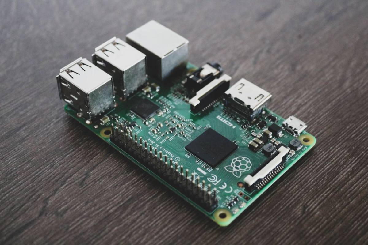
Вот в чём дело: если вы пытаетесь развернуть тепловизионную съёмку высокого разрешения на одноплатных компьютерах (SBC), таких как Raspberry Pi, вы, вероятно, столкнулись с определёнными трудностями. Ранние эксперименты с низкоразрешающими термопарными матрицами I2C подходили для любительских проектов, но современные промышленные приложения требуют серьёзного оборудования. Речь идёт о высокой тепловой чувствительности (NETD ≤ 50 мК), высокой частоте кадров и плотном пространственном разрешении. Это руководство представляет собой полное практическое руководство по системной интеграции для инженеров-аппаратчиков, специалистов по НИОКР и программных архитекторов, собирающих usb-тепловизионный модуль камеры для raspberry pi. В нашей мастерской мы знаем, что успех зависит от понимания физики, выбора правильного интерфейса, подбора оптики и написания эффективных программных конвейеров. Мы разберём физику неохлаждаемых длинноволновых инфракрасных (LWIR) датчиков, сравним грязные подробности интерфейсов USB/UVC и MIPI CSI-2, проанализируем выбор объективов и пройдём через готовый к использованию конвейер Python с использованием драйверов Linux V4L2 и OpenCV.
Содержание
- 👉 Физика LWIR-микроболометрических датчиков
- 👉 Интеграция USB и MIPI для Raspberry Pi
- 👉 Критерии выбора оптики и объективов
- 👉 Технические характеристики и выбор продукта
- 👉 Программная интеграция: V4L2, OpenCV и Python SDK
- 👉 Продвинутая обработка изображений: радиометрическое картирование и NUC
- 👉 Промышленные полевые развёртывания
- 👉 Технический углублённый FAQ
Физика LWIR-микроболометрических датчиков
Чтобы построить тепловую систему, которая действительно работает в полевых условиях, необходимо внимательно изучить лежащую в основе физику. Стандартные КМОП- и ПЗС-датчики улавливают отражённый видимый свет в диапазоне от 400 нм до 700 нм. Тепловидение — это другое. Мы смотрим на длинноволновой инфракрасный (LWIR) диапазон, который простирается от 8 мкм до 14 мкм.
Всё вокруг нас — двигатели, механизмы, печатные платы, человеческие тела — излучает тепловую энергию в виде излучения абсолютно чёрного тела. Закон Планка и закон смещения Вина описывают это поведение. Когда мы вычисляем длину волны пикового излучения, закон Вина упрощает задачу:
λмакс = 2897,8 мкм·К / T
Если ваша цель находится при нормальной комнатной температуре 300 К (около 27°C или 80°F), её пиковое излучение приходится точно на 9,66 мкм. Это идеально попадает в центр атмосферного окна пропускания LWIR. Этот диапазон критически важен, поскольку атмосферные газы, такие как углекислый газ и водяной пар, не поглощают здесь много энергии, позволяя вашему сигналу достигать датчика с минимальным затуханием.
Теоретические показатели производительности:
Оксид ванадия (VOx) против аморфного кремния (a-Si): В полевых условиях матрицы на основе VOx предпочтительны для высококлассных приложений. Материал VOx демонстрирует превосходный температурный коэффициент сопротивления (TCR) по сравнению с кремнием. Это минимизирует тепловой шум и даёт более чистое исходное изображение. Выбор модуля тепловизионной камеры высокого разрешения 640x512 с неохлаждаемым LWIR-ядром на подложках VOx гарантирует, что исходная детализация цели остаётся чёткой в широком диапазоне рабочих условий.
Большинство защищенных коммерческих модулей камер используют неохлаждаемые микроболометры. Представьте массив крошечных подвешенных кремниевых мостиков, каждый из которых покрыт термочувствительным материалом, таким как оксид ванадия. Когда LWIR-фотоны попадают на пиксель, мостик нагревается, изменяя свое электрическое сопротивление.
Схема считывания (ROIC) пропускает смещенный ток через массив, измеряет эти изменения сопротивления и строит цифровую тепловую картину. Две ключевые переменные определяют, насколько хорошо работает датчик:
- ⚙️ Шаг пикселя: Расстояние между центрами соседних пикселей. Уменьшение этого расстояния с 17 мкм до 12 мкм позволяет упаковать массив 640x512 в компактное легкое ядро, которое помещается на небольших дронах или в тесных корпусах.
- ⚙️ NETD (шумовая эквивалентная разность температур): Это ваш эталон отношения сигнал/шум. Он определяет наименьшую разницу температур, которую может разрешить камера. Если вы проводите диагностику, чувствительную к деталям, вам нужен NETD ≤40 мК или ≤50 мК. Более высокие значения делают изображение похожим на старые телевизионные помехи.
Интеграция USB и MIPI для Raspberry Pi
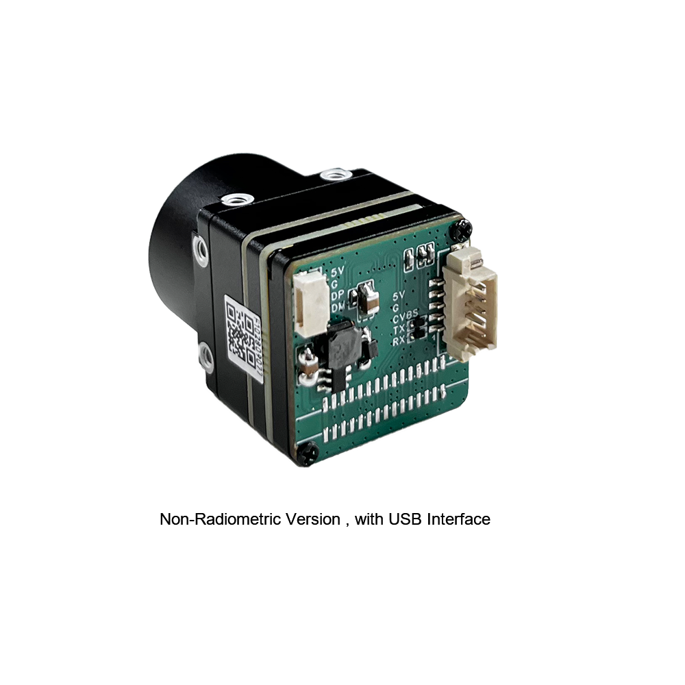
При интеграции высококлассного теплового ядра с Raspberry Pi вы сталкиваетесь с критической развилкой: использовать USB (протокол UVC) или нативный MIPI CSI-2?
USB-интерфейс (протокол UVC)
USB-модули полагаются на стандартный микрокод USB Video Class (UVC), работающий на встроенном микроконтроллере или FPGA. Чип упаковывает необработанный кадр ROIC в цифровой формат (YUYV или необработанный 16-битный оттенок серого) и передает его по шине USB.
Главное преимущество здесь — простота использования. Linux имеет встроенные uvcvideo драйверы, встроенные в ядро уже много лет. Подключите модуль, и он мгновенно появится как /dev/video0. Никаких пользовательских наложений дерева устройств, никаких ошибок компиляции и никаких проблем с соответствием ядра. Вы можете перенести ту же USB-камеру с Raspberry Pi 4 на Pi 5 или стандартный промышленный ПК на Linux x86, не меняя ни строчки кода. Компромисс? USB вносит немного более высокую задержку (обычно дополнительные 10–30 мс) и потребляет немного больше циклов ЦП из-за требований парсинга драйвера хост-контроллера.
Интерфейс MIPI CSI-2
MIPI CSI-2 — это высокопроизводительный вариант. Этот интерфейс обходит промежуточные микроконтроллеры, передавая необработанные последовательные буферы кадров напрямую в Video Core ISP SoC Raspberry Pi или системную RAM через DMA.
Если вы разрабатываете автоматизированные системы слежения или легкие устройства с батарейным питанием (например, подвесы дронов), где каждый миллисекунд и милливатт на счету, MIPI является стандартным выбором. Он предлагает низкую задержку и минимальную нагрузку на ЦП.
Недостатком является аппаратная жесткость. Вы должны компилировать наложения дерева устройств (.dtbo), специфичные для вашей точной версии ядра. Если вы обновите ОС, ваш конвейер камеры может сломаться, пока драйвер не будет исправлен. Физические соединения также деликатны; вы имеете дело с хрупкими ленточными кабелями или специальными микрокоаксиальными жгутами проводки. Если вы прокладываете через тугое вращающееся соединение, требуются специализированные высокоскоростные жгутовые сборки от экспертов, таких как Человек с микрокоаксиальным кабелем , чтобы сигналы оставались экранированными и чистыми.
Критерии выбора оптики и объективов
В отличие от стандартных камер, использующих недорогие стеклянные или пластиковые линзы, LWIR-конструкции требуют специализированных материалов, пропускающих инфракрасное излучение. Стандартное боросиликатное стекло полностью непрозрачно для LWIR-излучения. Вместо этого мы используем германий (Ge), кремний (Si) или формованные элементы из халькогенидного стекла.
| Материал | Показатель преломления (n @10мкм) | Key Engineering Characteristics |
|---|---|---|
| Germanium (Ge) | ~4.0 | Excellent transmission properties in the 8-14µm band; expensive; experiences thermal focus drift at operating limits. |
| Chalcogenide Glass (As-Se-Ge alloys) | ~2.5 to 2.8 | Highly moldable optics allowing complex geometries; minimal thermal focal drift; highly cost-effective index of refraction. |
When pairing a lens with your sensor, you need to calculate the spatial resolution. This is represented by the Instantaneous Field of View (iFOV) which tells you the physical field area a single pixel resolves at a given working distance:
iFOV = Pixel Pitch (µm) / Focal Length (mm)
Let's calculate this using a 640x512 resolution module with a 12 µm pixel pitch and a standard 9mm focus lens:
iFOV = 12 μm / 9 mm ≈ 1.33 mrad
This means at a range of 1 meter, each individual pixel resolves a physical square of 1.33 mm. At a distance of 100 meters, that footprint expands to 133 mm (about 5.2 inches). If you are looking for localized anomalies on utility poles or wind turbines, a target must cover at least 3x3 pixels to ensure reliable measurement. This makes focal length selection critical before deploying your hardware.
For demanding applications, precision-molded chalcogenide lenses from technology leaders like LightPath Technologies provide high light transmission while maintaining focus across wide temperature swings. This minimizes the need for continuous software focus corrections during outdoor operation.
Технические характеристики и выбор продукта
For hardware builds on the Raspberry Pi architecture, we offer two industrial-grade uncooled microbolometer sensor modules. One is designed for plug-and-play USB deployment, and the other is a native MIPI module built for direct, low-latency interfacing.
Product 1: Uncooled LWIR USB Mini 640*512 Thermal Imaging Camera Core Module For Drones Similar To DJI

This mini uncooled infrared thermal imaging module delivers sharp, detailed performance in an ultra-compact form factor. It is ideal for drone payloads and remote industrial monitoring systems.
Key Technical Specifications:
| Form Factor / Size | Ultra-miniature 21mm * 21mm footprint |
| Lens Options (Focal Length) | 5mm / 9mm / 13mm / 18mm / 35mm / 50mm / 75mm / 100mm / 150mm selections |
| Resolution Options | High-density 640x512 matrix (with 640x480 crop compatibility) |
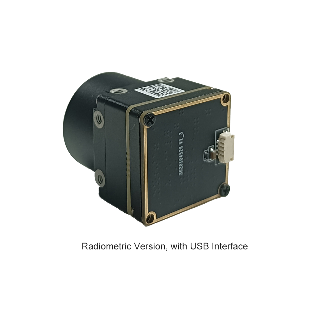
| Integration Compatibility | Robust structural sealing, thermal stability, standard UVC compliant over USB |
Product 2: Uncooled Infrared Mipi 640 384 256 9mm Thermal Imaging Camera Module For Drones

The Mini2 series MIPI thermal imaging module streams raw thermal data with minimal latency. It is optimized for direct processing loops and lightweight aerial systems.
Key Technical Specifications:
| Primary Resolution | 640x512 active pixel matrix (with 384 and 256 structural options) |
| Default Optics | 9mm high-quality Germanium focal lens configuration |
| Hardware Interface | Direct MIPI CSI-2 signaling (optimized for minimal latency and direct hardware processing) |
| Imaging Profile | Sharp and crisp thermal image presentation, lightweight design for drones and aerial platforms |
Программная интеграция: V4L2, OpenCV и Python SDK
Let's get our hands dirty with some code. To pull raw, uncompressed frames from a UVC thermal camera on a Raspberry Pi, we use the standard Linux Video4Linux2 (V4L2) driver.
Step 1: Check the System Properties
Before writing code, verify that the OS sees your camera. Plug the camera in and run:
# Install v4l2 utility toolkit
sudo apt-get update && sudo apt-get install -y v4l-utils

# List all connected video units
v4l2-ctl --list-devices

# Query supported resolution, formats, and frame-rate configurations
v4l2-ctl -d /dev/video0 --list-formats-ext
Look for frame formats like YDUV, YUYV, or direct 16-bit greyscale (labeled as Y16 или GREY). If your pipeline needs direct radiometric measurements, the raw 16-bit format is what you want.
Step 2: Real-World Multithreaded Python Capture
If you call VideoCapture.read() in a single-threaded Python loop, your frame rate will lag. In the shop, we run the sensor capture in a dedicated background thread to prevent blocking. This keeps the camera pipeline steady while you run heavy computer vision tasks on the main thread.
"""
RPi LWIR Thermal Acquisition and Multi-Threaded Frame Buffer Pipe
Optimized for 640x512 Uncooled USB Camera Cores.
"""

import cv2
import numpy as np
import time
import threading

class USBThermalCamera:
    def __init__(self, device_index=0, width=640, height=512):
        self.device_index = device_index
        self.width = width
        self.height = height
        self.cap = None
        self.frame = None
        self.running = False
        self.lock = threading.Lock()

    def initialize_capture(self):
        # Open video device via standard V4L2 utility backend
        self.cap = cv2.VideoCapture(self.device_index, cv2.CAP_V4L2)
        if not self.cap.isOpened():
            raise RuntimeError(f"Failed to access V4L2 sensor node: /dev/video{self.device_index}")

        # Bind payload stream resolutions to the requested parameters
        self.cap.set(cv2.CAP_PROP_FRAME_WIDTH, self.width)
        self.cap.set(cv2.CAP_PROP_FRAME_HEIGHT, self.height)

        # Verify active driver configuration values
        active_w = int(self.cap.get(cv2.CAP_PROP_FRAME_WIDTH))
        active_h = int(self.cap.get(cv2.CAP_PROP_FRAME_HEIGHT))
        print(f"[INFO] Camera pipeline running at target configuration: {active_w}x{active_h} px")

    def start_grab_thread(self):
        self.running = True
        self.thread = threading.Thread(target=self._update_loop, daemon=True)
        self.thread.start()

    def _update_loop(self):
        while self.running:
            ret, raw_frame = self.cap.read()
            if not ret or raw_frame is None:
                time.sleep(0.005)
                continue

            with self.lock:
                self.frame = raw_frame.copy()

    def grab_latest_frame(self):
        with self.lock:
            if self.frame is None:
                return None
            return self.frame.copy()

    def terminate_pipeline(self):
        self.running = False
        if hasattr(self, 'thread'):
            self.thread.join(timeout=1.0)
        if self.cap:
            self.cap.release()
        print("[INFO] Thermal core pipeline shutdown gracefully.")

if __name__ == "__main__":
    cam = USBThermalCamera(device_index=0, width=640, height=512)
    try:
        cam.initialize_capture()
        cam.start_grab_thread()
        print("[PROCESS] Streaming initialized. Press 'Q' to safely exit.")

        while True:
            frame = cam.grab_latest_frame()
            if frame is None:
                time.sleep(0.01)
                continue

            # Convert incoming YUYV channel arrays to basic greyscale structures
            gray_frame = cv2.cvtColor(frame, cv2.COLOR_BGR2GRAY)

            # Apply dynamic colormaps to visually enhance thermal variance
            # COLORMAP_INFERNO outputs excellent human eye thermography separation
            thermal_color = cv2.applyColorMap(gray_frame, cv2.COLORMAP_INFERNO)

            # Identify absolute thermal peaks within the target frame space
            min_val, max_val, min_loc, max_loc = cv2.minMaxLoc(gray_frame)

            # Draw tracking overlay representing the peak thermal zone
            cv2.circle(thermal_color, max_loc, 8, (0, 0, 255), 2)
            cv2.putText(thermal_color, f"PEAK: {max_val}", (15, 30),
                        cv2.FONT_HERSHEY_SIMPLEX, 0.6, (0, 255, 0), 2)

            cv2.imshow("LWIR 640x512 Realtime Core Pipeline", thermal_color)
            if cv2.waitKey(1) & 0xFF == ord('q'):
                break

    except Exception as err:
        print(f"[FATAL EXCEPTION]: {err}")
    finally:
        cam.terminate_pipeline()
        cv2.destroyAllWindows()
Продвинутая обработка изображений: радиометрическое картирование и NUC
Raw video data is just the beginning. Setting up a professional thermal monitoring solution requires two advanced processing steps: Non-Uniformity Correction (NUC) и Radiometric Mapping.
Non-Uniformity Correction (NUC)
Because microbolometer pixels are tiny and suspended, their raw electrical properties shift over time as the camera body warms up. This drift results in a noisy, grainy image—an effect called "spatial pattern noise."
To fix this, high-performance camera cores drop a small internal mechanical shutter in front of the optical sensor for a fraction of a second. This presents a perfectly uniform thermal target to the array. The internal processor measures the raw pixel values against the average, generating an offset correction map. While our modules can run this calibration automatically, developers working with precise radiometric systems often trigger this correction manually via serial commands to avoid interruptions during critical recordings.
Radiometric Temperature Calibration
For industrial temperature measurement, you need a radiometric setup. Instead of rendering standard 8-bit visual values, the module exports a raw 16-bit integer representing the actual ADC intensity of each pixel. High-performance modules typically use a standard linear scale:
Ttarget = (Pixel Value × Scale Factor) - Offset
If your module uses a standard 0.01K scaling factor, transforming raw pixel readings into Celsius or Kelvin is straightforward:
T (Kelvin) = ADC_Pixel_Value × 0.01
T (Celsius) = (ADC_Pixel_Value × 0.01) - 273.15
In real-world applications, you must also adjust for **Target Emissivity (ε)**. This value describes how efficiently an object radiates heat compared to a theoretical blackbody (where ε = 1.0). If you are measuring polished metals like electrical copper or aluminum bushings, their emissivity can drop to 0.15 or less. This means the raw sensor will pick up ambient heat reflections rather than the actual temperature of the metal. To get accurate readings, you must adjust your post-processing math to correct for these reflections:
def calculate_absolute_temp(pixel_value, emissivity=0.95, t_ambient_k=298.15):
    # Convert standard sensor output straight to Kelvin
    t_apparent_k = pixel_value * 0.01

    # Correct for surface reflection properties
    # Object energy = (Total Energy - Reflected Ambient) / Emissivity
    t_corrected_k = ((t_apparent_k ** 4 - (1.0 - emissivity) * (t_ambient_k ** 4)) / emissivity) ** 0.25
    return t_corrected_k - 273.15
Промышленные полевые развёртывания
Here's how engineers are using these integrated 640x512 microbolometer boards in field deployments:
A. UAV Aerial Inspection and Drone Mapping
By mounting these lightweight thermal cores onto small drones, utility operators can conduct automated inspections of solar farms, wind turbine blades, and high-voltage transmission lines.
Using compact setups like the Raspberry Pi Compute Module 4 (CM4), flight teams can run real-time image stabilization and target georeferencing without adding excessive weight to the airframe, preserving flight times.
B. Industrial Automation & Continuous Thermal Monitoring
Inside manufacturing plants, machinery failures can cause costly downtime. Engineers deploy Raspberry Pi boards inside sealed, industrial enclosures to continuously monitor conveyor bearings, transformers, and physical assets like boilers.
These setups watch for temperature spikes based on standard what is a thermal camera used for profiling guidelines. If a component exceeds safe limits, the Raspberry Pi can trigger alerts directly over industrial field networks using protocols like Modbus TCP or MQTT.
C. Perimeter Security and Edge Intelligence
While standard cameras struggle in complete darkness, fog, or heavy vegetation, LWIR sensors excel. Combining a high-resolution 640x512 thermal core with lightweight Edge AI models (like TFLite YOLOv8) on a Raspberry Pi 5 allows for highly reliable intruder detection. This setup can spot human silhouettes hundreds of meters away while ignoring background noise like blowing branches and wind.
If you're looking for basic hardware setups and diagnostic tools, check out our general thermal integration guide. It covers structural enclosures and protective crystal windows for harsh, dusty environments.
Технический углублённый FAQ
Why should I upgrade from an I2C sensor like MLX90640 to a USB thermal camera module for Raspberry Pi?
Then there's the speed. I2C is a slow, serial interface. Even when overclocked, you're looking at a sluggish 4 to 8 Hz. The USB camera streams at a smooth 25 Hz over a native high-speed bus using standard UVC protocols.
Finally, there's resolution quality. Low-cost thermopile arrays suffer from high sensor noise, meaning their NETD is often around 100 mK to 150 mK. A professional VOx microbolometer core delivers an NETD ≤ 50 mK. This means you can resolve fine temperature differences down to 0.05°C, which is essential for details like tracing heat flow on circuitry or locating fluid leaks behind drywall.
How do I stream real-time thermal video on Raspberry Pi OS using your module?
uvcvideo kernel driver included in Raspberry Pi OS releases like Debian Bookworm or Bullseye. No custom drivers or kernel patches are required.
Once connected, you can capture frames directly in Python using standard OpenCV calls. To avoid lag, we recommend grabbing frames on a background thread and feeding them to your main application, where you can apply false-color maps like INFERNO or JET for clear visualization.
What is the active power consumption and thermal dissipation requirement for continuous operation?
If you're housing the camera inside a sealed enclosure or drone pod, recommend mounting it directly to an aluminum bulkhead or chassis using thermal tape or brass standoffs. Keeping the body of the module cool minimizes how often the internal NUC shutter needs to cycle, ensuring a more stable, uninterrupted video feed.
Can I perform absolute temperature measurement (radiometry) using these uncooled LWIR camera modules?
By applying our core's calibration offsets in your code, your program can convert those raw ADC values into actual Kelvin or Celsius readings in real time. Once you compensate for surface emissivity, the system delivers an absolute accuracy of within ±2°C.
📚 Ссылки и дополнительная литература
- ✅ Отраслевой стандарт: LightPath Technologies
- ✅ System Physical Buses: Человек с микрокоаксиальным кабелем
- ✅ Связанное руководство: High-Resolution 640x512 Thermal core integration