High Resolution Thermal Camera Module: 640x512 Uncooled LWIR Cores for Drones & DIY Builds
2026年6月9日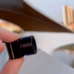
LWIR Micro Thermal Camera Module: The Ultimate Integration Guide for Drones and Edge AI Solutions
2026年6月10日
IR Thermal Camera Module Integration Guide: High-Res OEM Solutions for Drones & Edge AI
Let's be honest: bolting an ir thermal camera module into a modern tactical autonomous system, UAV payload, or industrial machine vision line is a completely different beast compared to standard visual-light gear. Standard visible-light RGB camera sensors operate by gathering reflected photons. Long-Wave Infrared (LWIR) camera modules, on the other hand, operate within the intense 8–14 μm spectral band. They detect heat—micro-Kelvin thermal radiation imbalances emitted directly by the targets themselves. This core physics difference completely changes how you handle mechanical integration, route your electrical signals, and process thermal metadata down in the firmware layers.
For payload systems designers, embedded AI developers, and defense engineers, translating raw thermal measurements into clear, actionable digital telemetry is a challenging integration pipeline. This exhaustive integration guide serves as your engineering blueprint. Below, we break down microbolometer sensor physics, hardware communication protocols, mechanical constraints, optical assembly selection, and radiometric edge-computing configurations. By establishing stable, low-latency interfaces, OEM integrators can leverage high-resolution uncooled ASIC thermal cores to unlock around-the-clock machine vision capabilities in the toughest operating environments.
Table of Contents
1. Core Microbolometer Architecture and Optical Selection
An uncooled ir thermal camera module uses an array of tiny, temperature-sensitive detector elements called a Focal Plane Array (FPA). Each pixel in this micro-electromechanical systems (MEMS) sensor is a suspended micro-bridge structures engineered with a active thermal absorption layer on top. This layer, typically made of Vanadium Oxide (VOx) or Amorphous Silicon (a-Si), changes resistance as it absorbs long-wave infrared radiation. The Readout Integrated Circuit (ROIC) sequentially samples this resistance change across the entire grid, translating those analog fluctuations into a 14-bit digital signal. Grasping these structural mechanics is closely related to understanding the foundational physics outlined in Wikipedia Thermal Imaging, which details how self-emitting thermal energy is cataloged without active illumination.
In the shop, we face two main challenges: thermal drift and mechanical vibration. Because the micro-bridges are extremely thin to minimize thermal mass, mechanical shock can distort the raw readings. Also, ambient temperature shifts can heat up the camera frame itself, overwhelming the target's thermal signal. This is why selecting the right sensor chemistry and microbolometer structure is critical from day one.
THERMAL IMAGING REAL-TIME VIDEO
Sensor Architecture Dynamics: VOx vs. Amorphous Silicon
Selecting the right chemical structure of your sensor array directly dictates performance in harsh operational environments:
- ✅ Vanadium Oxide (VOx): Features an exceptionally high Temperature Coefficient of Resistance (TCR), typically around -2% per Kelvin. This provides superior thermal sensitivity and lower 1/f noise characteristics, resulting in highly stable calibration curves and crisp image quality. This makes VOx the clear industry standard for tactical, professional UAV applications.
- ✅ Amorphous Silicon (a-Si): Offers a flatter response curve across wide temperature shifts because it is more chemically uniform and easier to deposit on large silicon wafers. However, its lower overall sensitivity often results in higher base noise levels and a tendency for sensor drift under rapid temperature changes.
Resolution, Pixel Pitch, and the Mathematics of NETD
Modern applications are shifting toward smaller pixel footprints, transiting from legacy 17μm arrays to highly compact 12μm pixel pitches. Moving to a 12μm pitch directly shrinks the overall FPA size. This breakthrough allows integrators to pair the sensor with smaller, lighter optical lenses, significantly optimizing system-level SWaP footprints while preserving high spatial resolution. By keeping a 640×512 resolution format on a 12μm node, developers achieve wider fields of view (FOV) and deeper detection ranges than simpler 384×288 frameworks.
A module's baseline sensitivity is measured by its Noise Equivalent Temperature Difference (NETD), expressed in milli-Kelvins (mK). Mathematically, NETD represents the exact scene temperature change on a blackbody target that yields a signal-to-noise ratio of exactly one:
Where Vn is the root-mean-square electrical noise, R is the thermal responsivity, and ΔT is the temperature gradient. An NETD of ≤ 40mK or ≤ 50mK indicates that the camera can resolve minute temperature differences of just 0.04°C to 0.05°C. This is critical for detecting targets in heavy fog, high humidity, or complex terrain where thermal gradients are minimal.
To put this in perspective: in high-humidity coastal environments, standard visible cameras blind out completely. An uncooled microbolometer with ≤ 40mK sensitivity can easily cut through the moisture. It resolves subtle thermal differences between dynamic targets and their watery backgrounds by tracking tiny differences in how they emit heat.
Infrared Optics: Germanium and Chalcogenide Lenses
Standard optical glasses like silicon dioxide block long-wave infrared waves. As a result, LWIR optics must be cut from specialized infrared-transmitting materials. Monocrystalline Germanium (Ge) is highly prized for its exceptionally high refractive index (roughly 4.0), enabling compact lens designs with fast optical apertures (F/1.0 or F/1.1) that capture maximum incoming thermal energy. However, Germanium has a major drawback: its refractive index shifts significantly with temperature (dn/dT equal to 3.96 × 10⁻⁴ K-1). This thermal drift causes visible focal shifts as ambient temperatures fluctuate during flight.
To mitigate weight and offset costs, optical design relies on specialized Chalcogenide glasses. These synthetic, moldable glass structures (such as BD-2 or IG6) boast a far lower thermal coefficient of refractive index, making them perfect for designing passive, athermalized, fixed-focus lens assemblies that stay sharp from -40°C to +80°C. Optical innovators like LightPath Technologies design precise Chalcogenide and molded Germanium lenses that reduce chromatic aberrations for dual-FOV or long-range mission payloads. For applications requiring extreme standoff ranges, developers can pair these modules with high-end, heavy-duty optical components, such as those found on high-performance 1280x1024 12µm optical systems designed for maximum long-range detection.
2. Hardware and Digital Stream Interfaces
Look, when you interface an ir thermal camera module with host processors (such as NVIDIA Jetson, Edge TPUs, or industrial Single Board Computers), your choice of physical layer and transfer protocol directly impacts processing latency, system stability, and driver complexity:
Designing within these specifications is critical. For instance, while streaming via an RJ45 IP interface allows you to route compressed H.264 video streams over long distances using standard switches, the internal compression step on the integrated ASIC adds processing latency. Alternatively, USB UVC streams uncompressed 14-bit frames or 8-bit visual buffers with lower latency, making it ideal for real-time edge processing. However, keeping the cable runs under three meters is essential to avoid timing desynchronization.
For setups that interface directly with custom PCB expansion boards, parallel 14-bit streams route the direct digitizations of the ROIC straight into the processor's input buffers. Although this method provides near-zero latency, it requires writing complex device drivers (such as Linux V4L2 device trees) and routing highly sensitive differential signal lines with strict impedance matching.
3. High-Res OEM Product Solutions
To implement these interface technologies, integrators can select from high-performance uncooled VOx core assemblies depending on their system constraints. Below are two industry-proven sensor options designed for rapid hardware deployment.
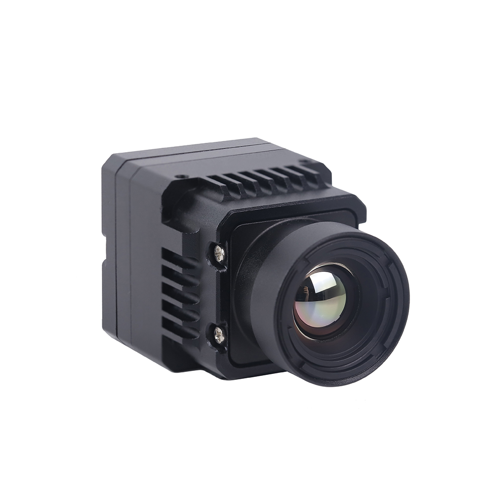
A. Uncooled Infrared RJ45 CVBS RTSP IP 640*512 ASIC Thermal Sensor Camera Module
Built on a powerful ASIC-centered image processing core, this design offers both network-ready digital and analog connectivity in an integrated package. It is engineered specifically for autonomous monitoring stations, pan-tilt-zoom (PTZ) arrays, and real-time security systems requiring multi-path signal outputs.
Critical Specifications:
- ⚙️ FPA Resolution: 640×512 pixels (highly accurate 12μm pitch VOx array)
- ⚙️ Dual Output: Simultaneous digital RTSP stream over RJ45 Ethernet and raw CVBS analog composite video
- ⚙️ On-Board ASIC: Real-time hardware-accelerated non-uniformity correction, digital zoom, and multi-palette color mapping
- ⚙️ Target Use: Persistent perimeter security, robotic surveillance rigs, and networked AI nodes
View Product Details & Pricing ➔
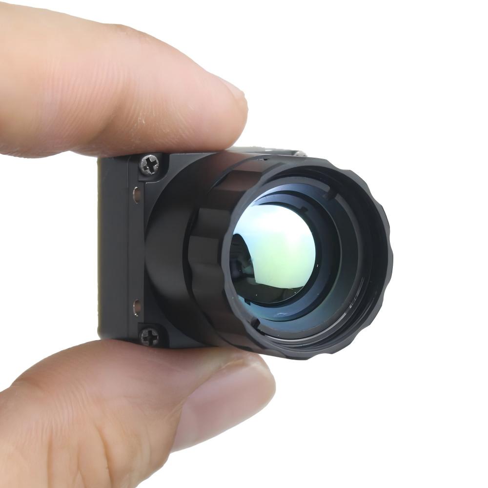
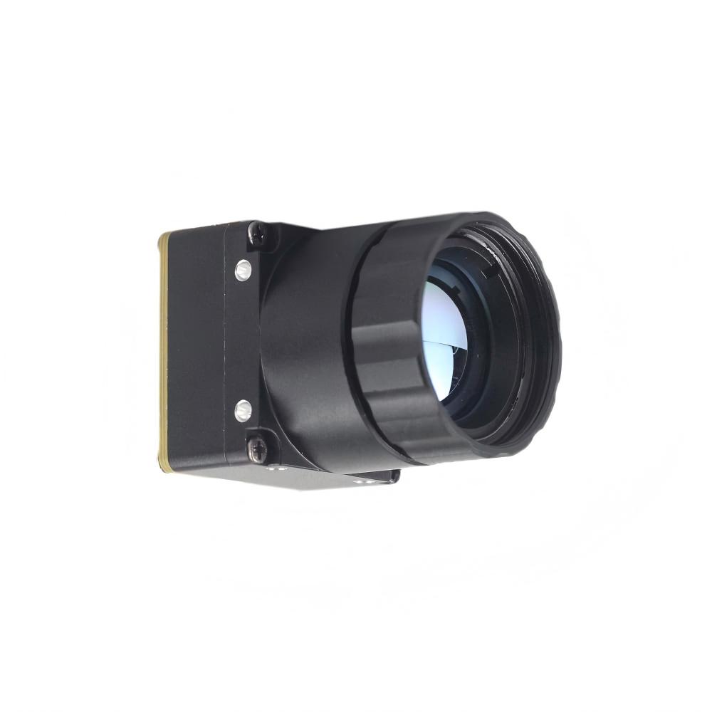
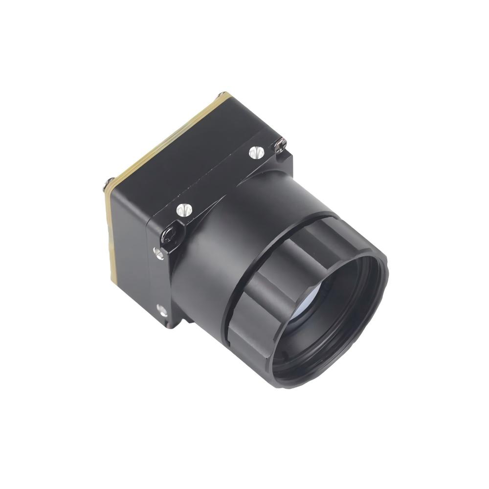
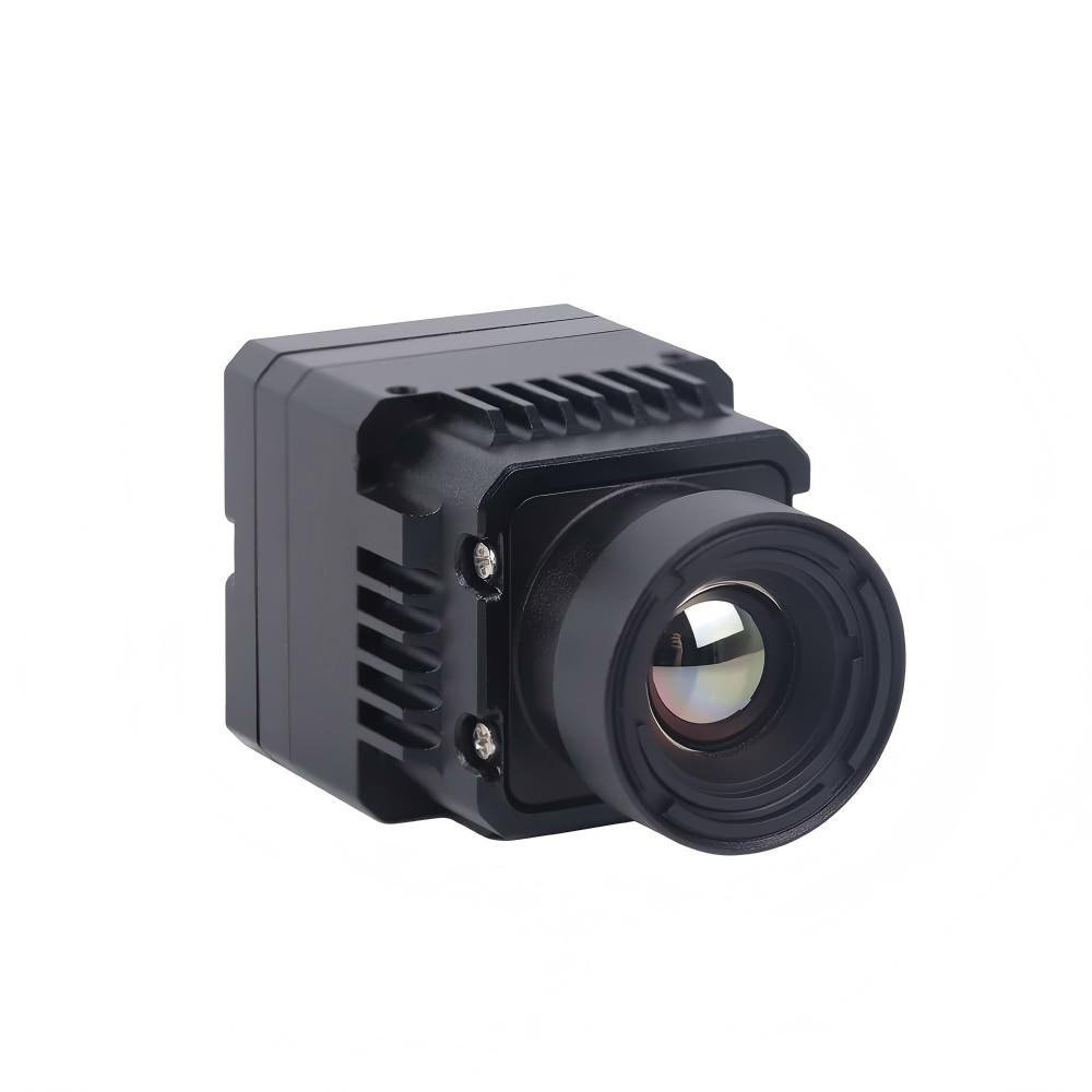
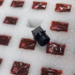
B. Uncooled LWIR USB Mini 640*512 Thermal Imaging Camera Core Module For Drones
When weight and physical volume are your primary design constraints, this micro-core offers a solution similar in performance to DJI industrial thermal payloads. Measuring just 21mm × 21mm, it is designed for direct integration into weight-critical drone gimbals and compact handheld systems.
Critical Specifications:
- ⚙️ Form Factor: Ultra-miniature 21mm × 21mm footprint
- ⚙️ Wide Lens Ecosystem: Threaded mount supports focal lengths including 5mm, 9mm, 13mm, 18mm, 35mm, 50mm, 75mm, 100mm, and 150mm
- ⚙️ Resolution Options: Native 640×512 layout with 640×480 resolution options
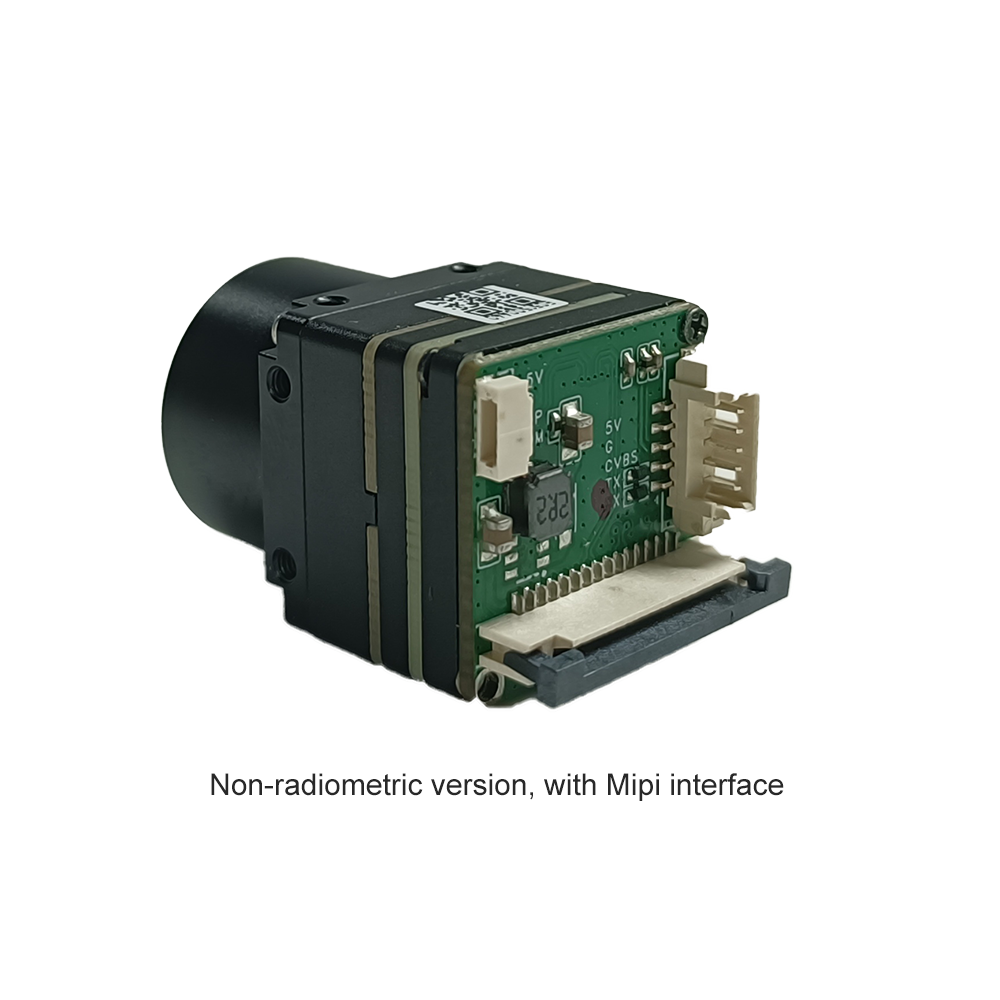
- ⚙️ Host Connectivity: Plug-and-play UVC protocol via standard USB, ensuring simple integration with Linux and Android systems

View Product Details & Pricing ➔
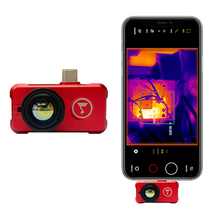
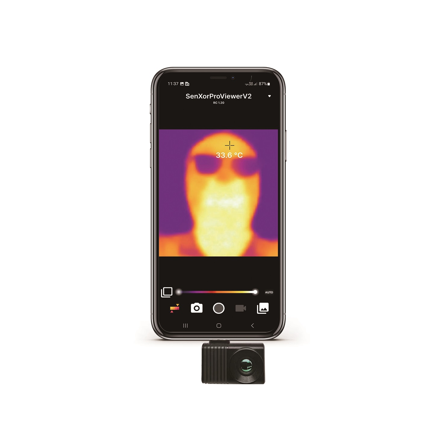
For architectural variations that require simpler resolution brackets relative to budget layouts, engineers can use the smaller MD Series 384x288 LWIR uncooled thermal core modules. Alternatively, for rapid field-testing, dynamic spot validations, or plug-and-play prototyping, you can utilize a mobile-compatible Android USB thermal camera to quickly capture imagery and calibrate target fields in real time.
4. Drone Integration Engineering
Here’s the deal: physical drone integration is where standard engineering concepts often fail. You are mounting a highly temperature-sensitive sensor inside a carbon-fiber housing that is constantly shaken by high-frequency motor vibrations and subjected to massive electromagnetic interference (EMI) from nearby Electronic Speed Controllers (ESCs). If you don't design your payload around these realities, your clean thermal signal will end up looking like static on an old CRT TV.
SWaP-C Optimization and Mechanical Isolation
Every gram of excess payload weight directly reduces your drone's flight window. For weight-critical systems, custom camera enclosures should be machined from lightweight 6061-T6 aluminum or printed using carbon-fiber-filled thermoplastic materials like PA12-CF. Aluminum alloy offers a distinct advantage by doubling as an EMI shield and an efficient passive heat sink.
Unlike cooled sensors, uncooled microbolometers do not require power-hungry cryogenic cooling engines. However, because their sensor calibration is highly sensitive to ambient temperature changes, heat from nearby electronics can warm the microbolometer FPA. This localized heating causes "thermal drift," showing up as spatial noise or cloud-like artifacts on your video feed. To prevent this, isolate the ir thermal camera module with low-conductivity mounting spacers made from PEEK or Ultem. Additionally, use high-conductivity thermal interface materials (with a thermal conductivity of ≤ 5 W/mK) to vent heat away from the rear ASIC components to the outer metallic frame of the gimbal assembly.
Electrical Isolation and Power Supply Filtering
A drone’s electrical system is a challenging environment for sensitive sensor arrays. Brushless electronic speed controllers (ESCs) and high-power motors generate significant switching noise and voltage sags across the raw battery terminals. This high-frequency noise can degrade the performance of the microbolometer's sensitive ROIC.
To maintain clean power delivery, isolate the module's supply lines from the main battery bus:
- ⚙️ Dual-Stage Filtration: Route power through a high-efficiency switching buck regulator to step voltage down to 5.5V-6.0V, followed by a dedicated high-rejection Low-Dropout (LDO) linear regulator to lock in a clean, ripple-free +5.0V output (≤ 10mV peak-to-peak ripple). This prevents electrical noise from bleeding into your raw thermal frames.
- ⚙️ Proper Shielding: Enclose high-speed digital lines (such as USB and MIPI arrays) in tin-plated copper shielding socks, and ground code lines at a single common grounding point on the power management card to avoid ground loops.
Communication Integrations using MAVLink Control Loops
To capture payload data and adjust settings from a ground control station, the drone's autopilot (running PX4 or ArduPilot) must translate MAVLink commands into instructions the thermal camera module can understand:
- ⚙️ Triggering Calibration (NUC): Uncooled bolometers regularly run a mechanical shutter calibration called Non-Uniformity Correction (NUC) to reset pixel response variations. Map a dynamic MAVLink command (such as
MAV_CMD_DO_DIGITAL_IMAGER_CONTROL) directly to a serial output channel on the autopilot to manual trigger the camera shutter before critical scanning tasks. - ⚙️ Palette Switching: Send serial control packets via UART or RS232 interfaces to switch the module's internal lookup tables (LUTs) in real time. This allows pilots to jump from "White-Hot" or "Black-Hot" modes to high-contrast "Ironbow" palettes during Search and Rescue (SAR) operations.
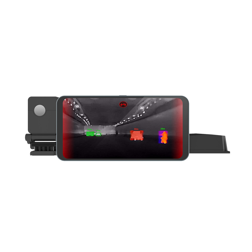
5. Edge AI and Radiometric Sensor Fusion
For automated target tracking, gas leaks detection, and structural anomaly mapping, feeding flat video output into a machine learning model is not enough. Systems must utilize the raw 14-bit radiometric stream to preserve accurate thermal measurement data.
Extracting Precise Radiometric Temperature Data
In automatic tracking platforms, standard 8-bit visual images (0-255 pixels) lack the depth of detail of raw sensor data. Instead, engineers capture raw 14-bit streams (0-16383 values) to capture every micro-Kelvin measurement. Converting these raw pixel values into actual temperature readings (Celsius) is typically done with a simple linear equation:
For standard uncooled sensor arrays, the scaling factor is 0.1K per Least Significant Bit (LSB). Subtracting the Kelvin offset (273.15) converts the scale to Celsius. The following Python template shows how to read raw 14-bit data vectors, calculate localized temperatures, and generate normalized visual maps using Python and open-source computer vision libraries:
import cv2
import numpy as np

def convert_and_process_radiometric(raw_14bit_array):
    # Establish default uncooled VOx calibration constants
    scaling_slope = 0.1
    kelvin_offset = 273.15

    # Calculate spot temperature in Celsius across the array
    celsius_grid = (raw_14bit_array * scaling_slope) - kelvin_offset

    # Extract structural extremes for localized evaluations
    absolute_min, absolute_max, min_x_y, max_x_y = cv2.minMaxLoc(celsius_grid)

    # Normalize the frame to 8-bit to display and run AI inference
    normalized_8bit = cv2.normalize(raw_14bit_array, None, 0, 255, cv2.NORM_MINMAX, dtype=cv2.CV_8U)
    visual_color_mapped = cv2.applyColorMap(normalized_8bit, cv2.COLORMAP_JET)

    return celsius_grid, visual_color_mapped, absolute_max, max_x_y

# Integration Application Example
# raw_sample = read_usb_14bit_driver_frame()
# temperatures, color_map, max_temp, coordinate = convert_and_process_radiometric(raw_sample)
# print(f"Hot-spot verified: {max_temp:.2f}°C located at coordinates {coordinate}")
Multi-Spectral Alignments and Bi-Spectral Sensor Fusion
To maximize situational awareness, engineers often combine high-resolution visible-light RGB sensors with uncooled thermal cameras. However, overlaying these two fields of view presents two technical challenges: Parallax Errors (caused by the physical distance between the lenses) and differences in Spatial Resolution (such as pairing a 1080p visible camera with a 640×512 thermal core).
To resolve these spatial differences, systems calculate a 2D affine transformation matrix. By aligning known, high-contrast thermal and optical calibration targets on a flat surface, you map pixel coordinates from the thermal camera onto the visible-light image:
Where the transformation matrix M handles scale, rotation, and alignment translations. Once calibrated, this step ensures that when your AI model (such as YOLOv8) detects a target, the visual bounding box matches the thermal reading with pixel-level precision. This enables robust object tracking across changing lighting conditions.

6. Deep-Dive OEM Integration FAQ
Q1: How do I achieve real-time, low-latency thermal streaming on a Raspberry Pi or other SBC?
cv2.VideoCapture with V4L2 and requesting raw Y16 (16-bit) streams avoids color-space conversion overhead. This allows the host card to focus on edge AI inference and metric tracking, maintaining stable video framerates of 30Hz or 50Hz.
Q2: Which thermal module is best for weight-sensitive applications like DIY or commercial drones?
Q3: Can these thermal sensor modules output raw temperature data for custom AI algorithm analysis?
📚 References & Further Reading
- Industry Standard: Explore advanced thermal optics design and chalcogenide material developments at LightPath Technologies.
- Underlying Physics: Understand the electromagnetics of radiation and microbolometer properties at Wikipedia Thermal Imaging.
- System Setup Reference: Review alternative uncooled cores for industrial integration at our MD Series Uncooled Core Guide.

