Choosing the Right Thermal Camera Core for Predictive Maintenance: OEM Guide
2026年10月9日
Fire Detection Thermal Camera Module: OEM Cores for Drones & Early Warning Systems
2026年10月10日
Best Thermal Module for Security Camera: OEM Integration & Selection Guide
Automated perimeter surveillance and critical infrastructure protection have decisively outgrown conventional visible-light and near-infrared (NIR) illuminated camera systems. In practical outdoor deployments, adverse atmospheric conditions—such as dense radiation fog, maritime haze, driving rain, particulate-laden dust storms, and industrial smoke—induce severe Rayleigh and Mie scattering across visible wavelengths. These scattering phenomena dramatically attenuate optical scene contrast, blinding standard Charge-Coupled Device (CCD) and Complementary Metal-Oxide-Semiconductor (CMOS) sensors. When visual input degrades, downstream rule-based computer vision engines and automated deep learning Video Analytics Architectures (VAA) suffer from unacceptable false-alarm rates or catastrophic missed detections. Integrating an uncooled Long-Wave Infrared (LWIR) thermal module for a security camera circumvents these physical constraints entirely. Rather than capturing reflected ambient or artificial light, an LWIR microbolometer directly measures the blackbody thermal radiation emitted by all physical matter in the 8 to 14 micrometer (µm) spectral band, yielding consistent, actionable contrast signatures across day, total darkness, and heavy obscurants.
For original equipment manufacturers (OEMs), defense contractors, security camera systems integrators, and embedded vision engineers, specifying the optimal thermal imaging core is a multifaceted engineering challenge. The selection process extends far beyond simply picking a display resolution. Engineering teams must rigorously balance detector physics—such as Vanadium Oxide (VOx) versus Amorphous Silicon (α-Si) thin-film thermistors—with baseline Noise Equivalent Temperature Difference (NETD), system-level thermal time constants, and mechanical shutter reliability. Furthermore, physical integration requires careful matching of target acquisition metrics via Johnson's Criteria against Germanium lens optical transmissions, f-number constraints, athermalization stability, and high-throughput, low-latency electrical bus interfaces ranging from MIPI CSI-2 to USB UVC and embedded IP encoder engines.
Table of Contents
- 👉 1. Core Microbolometer Physics & Sensor Architecture
- 👉 2. Resolution, Pixel Pitch, and Spatial Sampling Dynamics
- 👉 3. Optical Engineering: Germanium Optics & Target Range Profiling
- 👉 4. Embedded Electrical Interfaces: MIPI CSI-2, USB UVC, and IP Connectivity
- 👉 5. Edge AI Processing, VMS Pipeline & Network Encapsulation
- 👉 6. OEM Product Benchmark & Comparative Specifications Matrix
- 👉 7. Engineering Deep-Dive FAQ
1. Core Microbolometer Physics & Sensor Architecture
At the center of any modern uncooled security thermal camera core lies the Focal Plane Array (FPA) microbolometer. Unlike cryogenic photon detectors—such as Indium Antimonide (InSb) or Mercury Cadmium Telluride (MCT) sensors that operate within the Mid-Wave Infrared (MWIR) spectrum (3 to 5 µm) and necessitate bulky, power-hungry, maintenance-intensive split-Stirling mechanical coolers—uncooled microbolometers function at ambient operational temperatures. They target the critical Long-Wave Infrared (LWIR) atmospheric transmission window between 8 and 14 µm. This region coincides directly with the peak electromagnetic radiant emittance of terrestrial objects, wildlife, vehicles, and human targets resting near standard ambient temperatures of 300 Kelvin (approximately 27°C or 80°F), as defined by Planck's radiation law and Wien's displacement law, where peak terrestrial emission occurs near 9.7 µm.
The individual sensing element of an uncooled microbolometer consists of a microscopic, thermally isolated membrane suspended over an underlying Silicon Readout Integrated Circuit (ROIC) by high-aspect-ratio support legs composed of titanium or platinum alloys. This suspended micro-bridge structure contains an active, heat-sensitive thermistor material coated with a dielectric absorber film, such as silicon nitride (Si3N4). The microbolometer functions as a thermal transducer: when incoming LWIR radiant flux is focused onto the bridge by transmissive infrared optics, the absorber layer captures the photons, converting their radiant energy into a measurable temperature change within the thermistor. The support legs are engineered to possess exceptionally high thermal resistance to minimize heat loss to the ROIC substrate, while an evacuated hermetic package—often achieving internal vacuum levels below 0.01 Pascals via wafer-level packaging (WLP)—eliminates convective heat exchange with the surrounding environment.
The two dominant thermistor materials utilized in modern commercial and industrial microbolometer production are Vanadium Oxide (VOx) and Amorphous Silicon (α-Si). While α-Si benefits from manufacturing compatibility with standard complementary metal-oxide-semiconductor (CMOS) foundry lines, Vanadium Oxide is overwhelmingly preferred for mission-critical security and defense monitoring applications due to its superior physical characteristics:
- ⚙️ Temperature Coefficient of Resistance (TCR): The fundamental metric governing microbolometer sensitivity is its TCR, which quantifies the fractional change in electrical resistance per degree of temperature shift. Vanadium Oxide consistently yields a TCR of -2% to -3% per Kelvin at room temperature (295 K), significantly outperforming amorphous silicon. This heightened intrinsic material sensitivity directly suppresses electrical noise within the readout circuit.
- ⚙️ Noise Equivalent Temperature Difference (NETD): Expressed in millikelvins (mK), NETD defines the minimal thermal differential between a target scene and its background required to produce a signal-to-noise ratio (SNR) of unity at the sensor output. High-performance uncooled VOx cores achieve NETD ratings of ≤35 mK to 40 mK at an optical aperture of f/1.0. A core characterized by a 35 mK NETD discerns minute thermal gradients as small as 0.035°C, enabling the host security system to resolve footprints left on concrete, hidden targets concealed beneath light camouflage or thin foliage, and residual thermal signatures from freshly operated motor vehicles.
- ⚙️ Thermal Time Constant (τ): The thermal response time defines how quickly the suspended microbolometer membrane absorbs radiant heat and dissipates it via thermal conduction through its support arms. High-density VOx structures reliably maintain a thermal time constant between 8 and 12 milliseconds (ms). This rapid response time prevents temporal latency, image ghosting, and streaking artifacts during standard operational frame rates (typically 25 Hz, 30 Hz, or 50 Hz/60 Hz), even when tracking fast-moving targets across an active perimeter.
Because microbolometer arrays are comprised of hundreds of thousands of microscopic, mechanically isolated bridges fabricated over silicon substrates, minor micro-lithographic variations inevitably exist from pixel to pixel. These variations manifest as non-uniform baseline electrical resistance and varying individual thermal responsivities, generating severe spatial fixed-pattern noise (FPN) across the raw image. Furthermore, as the camera housing undergoes ambient temperature swings (typically rated from -40°C to +80°C in mission-critical outdoor security environments), the internal substrate and enclosure emit varying parasitic blackbody radiation onto the sensor array, shifting baseline output levels continuously.
To overcome this drift, uncooled OEM thermal modules implement robust Non-Uniformity Correction (NUC) pipelines. The most traditional and reliable approach is a calibrated mechanical shutter mechanism. At programmed time intervals or whenever internal thermistors detect a substantial ambient temperature delta, an electromechanical solenoid momentarily inserts a blackened, uniform-temperature calibration paddle into the optical path between the rear element of the lens and the FPA. The camera core captures an instantaneous single-point or multi-point flat-field frame, calculates offset coefficients for every single micro-bridge, and updates an internal correction table to normalize output. For critical security environments where a 500-millisecond shutter calibration freeze could result in a dropped track of an intruder, modern OEM modules utilize advanced shutterless parametric algorithms. These engines combine deeply characterized multi-temperature factory lookup tables (LUTs) with real-time continuous scene-based spatio-temporal filtering, dynamically scrubbing fixed-pattern artifacts without requiring physical shutter actuations.
Following NUC normalization, the raw thermal data (typically running at a native dynamic range of 14 bits or 16 bits) is routed into advanced Dynamic Range Compression (DRC) and Dynamic Detail Enhancement (DDE) hardware pipelines. Because an uncooled core must simultaneously register freezing background terrain (e.g., snow at -10°C) and intense thermal points (such as vehicle exhaust manifolds operating at 400°C), standard linear down-sampling to 8-bit displays would wipe out subtle human thermal signatures. High-performance cores apply non-linear histogram equalization, high-pass spatial filtering, and bilateral edge-preserving smoothing. This preserves fine thermal details and localized contrast, ensuring both background terrain and human perimeter intruders remain clearly visible within standard 8-bit security displays.
2. Resolution, Pixel Pitch, and Spatial Sampling Dynamics
In thermal surveillance systems engineering, optical design begins with the spatial resolution of the Focal Plane Array and the physical size of its individual pixels, known as the pixel pitch. The spatial sampling capability of any camera core is fundamentally bounded by its Instantaneous Field of View (IFOV), which represents the geometric angular cone visible to an individual pixel within the overall matrix:
IFOV = d / f
Where d is the microbolometer pixel pitch dimension (in micrometers or millimeters) and f is the effective focal length of the objective lens (in millimeters). The resulting IFOV is expressed in milliradians (mrad). A smaller IFOV provides finer angular resolution, projecting a smaller spatial footprint onto a distant target, which directly enhances the system's effective standoff range.
For more than a decade, industrial and commercial microbolometer designs were centered on 25 µm and 17 µm pixel pitch architectures. The transition to modern 12 µm and even 10 µm Wafer-Level Packaging (WLP) has revolutionized uncooled LWIR performance. Shifting from a 17 µm to a 12 µm pixel pitch delivers transformative physical advantages to the hardware designer:
- ✅ Optical Miniaturization: For any given resolution format (e.g., 640 × 512), a 12 µm microbolometer array occupies a substantially smaller physical diagonal active surface area (approximately 9.83 mm) compared to a 17 µm equivalent (approximately 13.9 mm). Consequently, to achieve an identical angular Field of View (HFOV), an optical assembly engineered for a 12 µm sensor requires a lens with a much shorter focal length and a correspondingly smaller entrance pupil diameter. This directly translates into massive reductions in the physical volume, weight, and raw Germanium material cost of the objective lens assembly.
- ✅ Reduced Thermal Mass: The physical volume of each suspended microbolometer bridge scales down dramatically at the 12 µm node. This reduction in physical mass lowers the intrinsic heat capacity of the pixel, facilitating rapid thermal dissipation and shorter thermal time constants. As a result, 12 µm cores achieve superior frame-to-frame fidelity with reduced smearing when panning on fast pan-tilt-zoom (PTZ) positioners or tracking aerial targets.
- ✅ Payload Optimization: Compact 12 µm cores dramatically reduce the SWaP (Size, Weight, and Power) footprint of camera enclosures. This allows high-resolution thermal imaging to be packaged into ultra-low-profile security domes, discreet perimeter bollards, and compact dual-sensor unmanned aerial vehicle (UAV) gimbals where mechanical space and electrical power are strictly budgeted.
Choosing the correct resolution tier—ranging from entry-level 256 × 192 configurations up to tactical-grade 640 × 512 arrays—requires matching the specific spatial coverage needs of the perimeter layout against compute and budgetary allowances:
| Metric / Parameter | Entry-Tier (256 × 192) | Mid-Tier (384 × 288) | High-Tier (640 × 512) |
|---|---|---|---|
| Total Pixel Count | 49,152 active pixels | 110,592 active pixels | 327,680 active pixels |
| Active Area (at 12 µm) | 3.07 mm × 2.30 mm | 4.61 mm × 3.46 mm | 7.68 mm × 6.14 mm |
| Sensor Diagonal | 3.84 mm | 5.76 mm | 9.83 mm |
| Raw Digital Bandwidth (14-bit, 50 Hz) | ~4.3 MB/s (34.4 Mbps) | ~9.7 MB/s (77.4 Mbps) | ~28.7 MB/s (229.4 Mbps) |
| Typical Security Application | Short-range gates, entry turnstiles, small utility cabins (<30m range) | Medium perimeter fences, building facades, localized substations (<100m range) | Wide-area perimeters, border corridors, runways, high-value asset tracking (>250m) |
While an entry-level 256 × 192 array is adequate for detecting whether an intruder has crossed an immediate access portal, its utility drops off rapidly across extended perimeters. Because spatial sampling points degrade linearly with distance, a 256 × 192 sensor running a wide lens may only project one or two pixels across a human target at 50 meters, resulting in frequent false triggers caused by localized wildlife or warm background clutter. Conversely, a 640 × 512 array captures over 6.6 times the information density of an entry-level core, distributing sufficient pixels across targets at long range to facilitate automated target discrimination. For engineers navigating the practical mechanical layout and housing choices for these sensor arrays, reference material can be found in our uncooled thermal core integration overview.
3. Optical Engineering: Germanium Optics & Target Range Profiling
Optical engineering for long-wave infrared sensors presents distinct material challenges that do not exist in visible-spectrum system design. Standard optical crown and flint glasses (based on silicon dioxide, SiO2) are entirely opaque to electromagnetic radiation in the 8 to 14 µm spectrum; they absorb LWIR photons completely within fractions of a millimeter. Consequently, thermal modules require objective lenses manufactured from specialized transmissive materials, the most prevalent being monocrystalline Germanium (Ge), accompanied by specialized Chalcogenide glasses (e.g., Gasir).
Germanium boasts a very high refractive index (n ≈ 4.0 at 10 µm), allowing optical designers to produce high-power lenses with minimal surface curvature and reduced spherical aberrations. However, Germanium surfaces suffer from significant Fresnel reflection losses (approximately 36% reflection per untreated air-to-germanium interface). To counter this, security-grade Germanium lenses must be treated with high-durability Anti-Reflective (AR) coatings, or Hard Carbon Diamond-Like Coatings (DLC) on the outermost exposed front element. A DLC coating protects the soft optical substrate against airborne sand abrasion, saltwater spray, chemical corrosion, and mechanical scratching while maintaining high overall transmission (typically >90% to 94% across the LWIR spectrum).
Another crucial performance parameter is the optical speed, quantified by the lens f-number (F#), defined as the ratio of the lens focal length to its clear entrance pupil diameter. The radiant flux (irradiance, E) reaching the microbolometer FPA scales inversely with the square of the optical system's f-number:
E ∝ 1 / [4(F#)² + 1]
In high-performance security designs, optical assemblies are intentionally specified between f/1.0 and f/1.2. If an engineering team attempts to reduce optical assembly costs by utilizing an inferior, smaller-aperture f/1.6 lens, the thermal flux reaching the sensor drops by more than 55%. This directly degrades effective sensitivity: a sensor core with a bench-level NETD of 35 mK will see its system-level NETD deteriorate to approximately 80 mK or worse in operation. This severe loss in sensitivity causes subtle scene details to wash out, severely diminishing image clarity and system range during low-contrast conditions such as humid summer nights.
To mathematically quantify system detection range during site survey design, defense and industrial engineers rely on the classical Johnson's Criteria. The criteria model target acquisition performance based on resolving specific spatial line pairs (cycles) across the critical physical dimension of a target (defined as H_c = 0.75 meters for a standing human torso profile, and 2.3 meters for a standard motor vehicle):
- ⚙️ Detection (1.5 cycles across target / ≈ 3 pixels): An observer or computer algorithm can determine with 50% statistical probability that an object is present against the background. The object appears as an unclassified localized thermal hot spot.
- ⚙️ Recognition (6.0 cycles across target / ≈ 12 pixels): The system can distinguish the high-level operational class of the object (e.g., discerning a human intruder from a quadrupedal animal or a passenger car from a utility truck).
- ⚙️ Identification (12.0 cycles across target / ≈ 24 pixels): The system can discern fine structural details (e.g., identifying clothing type, verifying whether an individual is carrying an object, or classifying specific vehicle models).
The mathematical slant range (R, in meters) to achieve these thresholds is governed by the relationship:
R = (H_c × f) / (N × d)
Where H_c is the critical target dimension in meters, f is the lens focal length in millimeters, d is the pixel pitch in millimeters (e.g., 0.012 mm for a 12 µm sensor), and N represents the Johnson line-pair threshold (1.5 for Detection, 6.0 for Recognition, 12.0 for Identification). The table below calculates the standard human target acquisition limits for a modern 640 × 512, 12 µm VOx thermal core across common security focal lengths:
| Lens Focal Length (f) | Horizontal FOV (at 640×512) | Human Detection (1.5 cycles) | Human Recognition (6.0 cycles) | Human Identification (12.0 cycles) |
|---|---|---|---|---|
| 9.1 mm (Athermalized) | ≈ 48.0° | 379 meters | 95 meters | 47 meters |
| 19 mm Fixed Core | ≈ 22.9° | 791 meters | 198 meters | 99 meters |
| 35 mm Telephoto | ≈ 12.5° | 1,458 meters | 365 meters | 182 meters |
| 75 mm Long-Range | ≈ 5.9° | 3,125 meters | 781 meters | 390 meters |
When selecting optics for harsh outdoor deployments, engineers must specify athermalized lens assemblies. Standard Germanium exhibits an exceptionally high thermo-optic coefficient (dn/dT ≈ 4 × 10^-4 /°C), which is nearly an order of magnitude higher than standard optical glasses. Without mechanical or optical athermalization (combining specialized lens cell mount alloys with contrasting thermal expansion coefficients, or utilizing Chalcogenide optical elements with inverse thermo-optic drifts), ambient temperature swings cause significant focal plane defocusing, rendering high-resolution sensors blurry and ineffective.
4. Embedded Electrical Interfaces: MIPI CSI-2, USB UVC, and IP Connectivity
Bridging an uncooled thermal microbolometer module into a complete security camera system requires careful selection of the physical bus architecture and software protocol stack. The choice of interface directly determines processing latency, maximum interconnect trace length, host CPU overhead, and overall hardware bill-of-materials costs:
- ⚙️ MIPI CSI-2 (Mobile Industry Processor Interface Camera Serial Interface): MIPI CSI-2 represents the industry gold standard for integrated smart cameras, edge AI appliances, and compact drone vision payloads. Utilizing differential high-speed D-PHY signaling over two or four lanes, MIPI routes pure, uncompressed 14-bit or 16-bit raw radiometric frames directly into the hardware Image Signal Processor (ISP) or Video Input (VI) subsystem of modern system-on-chip (SoC) architectures. Embedded developers utilize platforms such as NVIDIA Jetson Orin/Xavier or compact compute modules like the Raspberry Pi CM4 to ingest raw frames with sub-5 millisecond processing latency. This near-zero transmission latency is essential for high-speed automated pan-tilt-zoom slewing systems, closed-loop tracking gimbals, and real-time radiometric flame detection. However, MIPI CSI-2 trace lines are limited by high-frequency attenuation and EMI constraints, requiring the thermal module to reside within 15 to 20 cm of the host compute engine on high-density flexible printed circuit (FPC) cables.
- ⚙️ USB 2.0 / USB 3.0 (UVC Class): For rapid laboratory prototyping, proof-of-concept system validation, and integration into industrial x86 perimeter surveillance servers, USB-enabled thermal camera modules offer a plug-and-play solution. USB modules present themselves to the host operating system as a standard USB Video Class (UVC) endpoint, supported natively by standard Linux Video4Linux2 (V4L2) kernel drivers and Windows DirectShow frameworks. While this eliminates the need for proprietary low-level register configuration drivers, USB stacks introduce slight hardware latency overhead (typically 15 to 30 ms) and require host CPU cycles to manage protocol packetization. Shielded USB lines allow cable runs of 3 to 5 meters, which is ideal for modular enclosures containing separate compute hubs.
- ⚙️ Direct IP SoC Integration (Ethernet / Power-over-Ethernet): In traditional fixed perimeter security installations where cameras are spaced across hundreds of meters of physical fencing, the thermal core must be paired with an IP encoder processor board. The encoder SoC receives digital pixel data (via parallel Digital Video Port [DVP] or MIPI), executes Dynamic Detail Enhancement and palette colorization in hardware, and encodes the stream into industry-standard H.264 or H.265 (HEVC) formats. The compressed video is then packetized over standard IPv4/IPv6 networks and streamed via Real-Time Streaming Protocol (RTSP) across standard Cat5e/Cat6 STP cabling spanning up to 100 meters per hop, or multi-kilometer corridors utilizing fiber optic SFP transceivers.
5. Edge AI Processing, VMS Pipeline & Network Encapsulation
The transformation of raw thermal infrared sensor data into actionable security intelligence requires a coordinated edge computing and video management pipeline. Modern perimeter defenses rarely rely exclusively on human operators monitoring raw video walls. Instead, continuous video analytics are deployed directly at the network edge to autonomously identify unauthorized intrusions, trigger automated deterrents, and log critical perimeter events.
A primary challenge when deploying deep learning models (such as YOLOv8, YOLOv9, or RT-DETR) onto thermal video streams is the fundamental domain shift between optical and thermal sensor characteristics. Standard computer vision models are pre-trained on massive RGB datasets (e.g., ImageNet, COCO) that depend heavily on chromatic contrast, internal texture features, and visual shadow variations. Because an uncooled LWIR thermal module outputs a single-band radiometric intensity map capturing surface radiance, visible color and internal texture are completely absent. As a consequence, running an off-the-shelf RGB object detection weight matrix directly on a thermal stream yields unacceptable misclassification rates. Advanced systems retrain deep convolutional backbones and transformer networks using multispectral infrared training libraries, optimizing the neural network weights to extract target geometry, radiant thermal gradients, and distinct temperature silhouettes against natural backgrounds.
Beyond standard intrusion tracking, radiometric thermal camera cores provide an absolute temperature measurement for every individual pixel within the Field of View. During raw 14-bit data extraction, the thermal core computes temperature via pre-calibrated Planck curve conversion formulas stored in internal non-volatile memory:
S_pixel = R_resp / [exp(B / T) - F]
Where S_pixel represents the digital count output, T is absolute temperature in Kelvin, and R_resp, B, and F represent factory-calibrated radiometric constants. This enables the integration of dual-factor rule verification algorithms directly at the edge: the computer vision model can detect an intruder's human shape while the radiometric calculation simultaneously confirms an elevated skin-surface signature (e.g., between 33°C and 38°C). This effectively eliminates false detections caused by animal crossings, drifting exhaust emissions, and wind-blown vegetation.
To ensure interoperability with commercial Video Management Systems (such as Milestone XProtect, Genetec Security Center, Qognify, or Network Optix), the camera subsystem must adhere strictly to the Open Network Video Interface Forum (ONVIF) standards:
- ⚙️ ONVIF Profile S & Profile T: Governs basic and advanced video streaming, providing H.264/H.265 stream negotiation over RTSP, dual-streaming parameters (high-resolution main-stream for recording, lower-resolution sub-stream for mobile viewing), and pan-tilt-zoom control interfaces.
- ⚙️ ONVIF Profile M: The modern industry standard for metadata exchange. Profile M allows the edge AI processor (running on the host SoC) to inject bounding boxes, centroid coordinates, target classifications ("Human", "Vehicle"), and precise geo-spatial telemetry directly into the video stream as XML or JSON metadata tracks, eliminating the need for high-bandwidth analytical re-processing at the central server.
Engineers seeking deeper operational insight into OEM industrial manufacturing rigor, ISO quality assurance, and high-volume module testing standards should review our overview of enterprise manufacturing capacity.
6. OEM Product Benchmark & Comparative Specifications Matrix
Selecting an OEM thermal module for a security camera requires balancing mechanical constraints against optical performance, detector pitch, and processing bus compatibility. Below is an engineering review of two industry-leading uncooled LWIR camera cores specifically designed for integration into perimeter surveillance domes, tactical PTZ systems, UAV security payloads, and industrial inspection arrays.
Product 1: Mini 640 Uncooled LWIR USB Thermal Camera Core Module
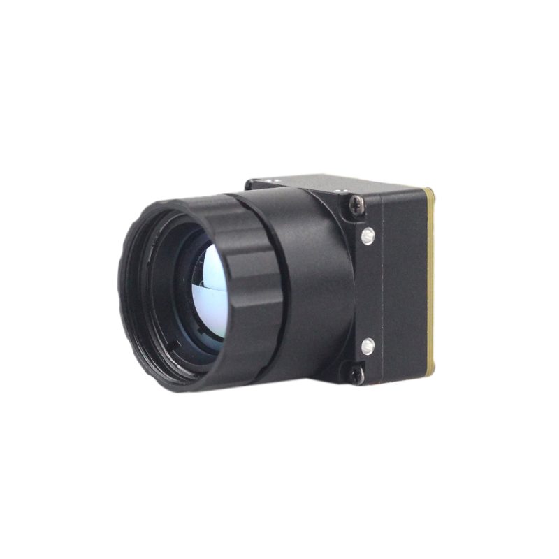
The Mini 640 Uncooled LWIR Thermal Imaging Camera Core Module is engineered for high-performance security and drone-based surveillance applications requiring sharp image presentation, an ultra-compact envelope, and broad optical versatility. Designed with an ultra-miniature 21 mm × 21 mm mechanical footprint, the core integrates seamlessly into space-constrained housings, pan-tilt positioners, and compact airborne payloads. It features an uncooled long-wave infrared microbolometer running a crisp 640 × 512 resolution (with selectable 640 × 480 modes), delivering low-noise thermal output with strong environmental stability across extreme ambient temperature shifts.
A standout technical advantage of the Mini 640 platform is its expansive lineup of modular optical configurations. Integrators can tailor the core precisely to their coverage envelope by selecting from an extensive range of athermalized and manual-focus Germanium objective lenses: 5 mm, 9 mm, 13 mm, 18 mm, 35 mm, 50 mm, 75 mm, 100 mm, and 150 mm. Whether configured with a 5 mm lens for ultra-wide perimeter awareness or a 150 mm telephoto lens for multi-kilometer perimeter defense, the core provides consistent optical clarity. Its versatile USB interface streamlines development, allowing vision engineers to rapidly ingest raw digital data or standard UVC streams directly into host computing hardware without specialized carrier boards.
| Core Parameter | Manufacturer Specification |
|---|---|
| Detector Architecture | Uncooled LWIR Microbolometer FPA (VOx) |
| Resolution | 640 × 512 native (640 × 480 optional) |
| Mechanical Dimensions | Mini-Size: 21 mm × 21 mm core envelope |
| Optical Lens Options | 5 / 9 / 13 / 18 / 35 / 50 / 75 / 100 / 150 mm |
| Interface Standard | High-Speed USB / Direct Digital Stream |
| Key Performance Attributes | Sharp image presentation, low cost, strong environmental adaptability |
View Product Details & Pricing ➔
Product 2: Mini2 640/384/256 9mm MIPI Thermal Imaging Camera Module
The Mini2 Uncooled Infrared Thermal Camera Module is specifically designed for integration into next-generation embedded security appliances, smart IoT camera sensors, and autonomous perimeter surveillance drones. Built around a high-speed MIPI interface, the Mini2 links directly into host Application Processors, bypassing the latency and protocol overhead inherent to traditional analog or USB conversion chips. It allows edge AI vision boards to capture uncompressed radiometric frames directly into the host memory bus, delivering the low-latency imaging required for closed-loop perimeter target tracking and instant alarm triggering.
The Mini2 platform provides flexible resolution options to match varying project requirements and budgets, offering 640 × 512, 384 × 288, and 256 × 192 sensor formats. Outfitted with an integrated, precision-aligned 9 mm athermalized lens assembly, the module delivers an ideal balance between wide spatial coverage and dependable target acquisition range. Its lightweight chassis and low operational power consumption make it especially suitable for mobile perimeter patrols, solar-powered security outposts, dual-spectrum battery-operated cameras, and compact aerial inspection systems.
| Core Parameter | Manufacturer Specification |
|---|---|
| Detector Architecture | Uncooled Infrared Microbolometer (VOx) |
| Selectable Resolutions | 640 × 512 / 384 × 288 / 256 × 192 |
| Integrated Lens | 9 mm high-performance athermalized optics |
| Data Bus Interface | MIPI CSI-2 Embedded Bus Output |
| Integration Target | Autonomous drones, smart IoT sensors, low-SWaP security payloads |
| Key Performance Attributes | Sharp image presentation, compact size, low cost, ultra-low latency |
View Product Details & Pricing ➔

7. Engineering Deep-Dive FAQ
How do I choose between MIPI, USB, and Ethernet when selecting a thermal module for a security camera?
⚙️ MIPI CSI-2: The premier choice for tightly integrated embedded vision systems and edge AI smart cameras. If your camera housing incorporates an onboard system-on-module (SoM) such as an NVIDIA Jetson or a Raspberry Pi Compute Module, MIPI transmits uncompressed 14-bit radiometric raw frames directly into the host Image Signal Processor (ISP). This yields the lowest possible video latency (under 5 milliseconds) and eliminates the hardware costs and power consumption of bridge chips. However, MIPI trace lengths are strictly limited to under 15–20 centimeters due to high-frequency differential signal degradation.
⚙️ USB 2.0 / USB 3.0 (UVC): Ideal for rapid prototyping, laboratory bench testing, and integration into systems powered by standard x86 industrial PCs. USB simplifies software development through universal Linux Video4Linux2 (V4L2) driver support and permits cable runs up to 3–5 meters, though it introduces slight operating system driver overhead and modest transfer latency (typically 15–30 ms).
⚙️ Direct IP SoC (Ethernet): Mandatory for standalone perimeter security cameras and remote network camera housings. The onboard encoder ingests the raw thermal sensor data, applies dynamic contrast adjustments, and compresses the stream into H.264/H.265 video streamed via RTSP/ONVIF. This architecture allows long cable runs up to 100 meters over standard twisted-pair Cat6 cabling (or several kilometers via optical fiber transceivers) straight to enterprise Video Management Systems (VMS), though compression and network packetization increase end-to-end display latency to between 80 and 180 ms.
Is a 256×192 resolution thermal core sufficient for driveway surveillance, or do I need 640×512?
✅ Entry-Tier 256×192 (49,152 active pixels): Represents an economical solution for localized, short-range coverage—such as monitoring a gated residential entrance or a narrow vehicle access point within 20 to 30 meters. However, when monitoring broad perimeters or extended driveways reaching 50 to 100 meters, a 256×192 array lacks the spatial resolution required for dependable target classification.
⚙️ Johnson's Criteria Considerations: According to Johnson's Criteria, an automated algorithm or human operator requires at least 6 line pairs (approximately 12 pixels across the critical dimension) to reliably distinguish a human intruder from local wildlife or drifting exhaust plumes. On a 256×192 sensor paired with a wide-angle lens, an individual standing 60 meters away occupies only 1 to 2 pixels. As a result, edge vision models (such as YOLO or classical background subtraction engines) cannot resolve target morphology, leading to frequent false alarms or missed detections.
✅ High-Tier 640×512 (327,680 active pixels): Provides over 6.6 times the spatial sampling density. Under identical optical conditions, it projects 12 to 24 pixels across that same 60-meter target. This provides the edge AI pipeline with rich morphological detail, ensuring accurate target recognition, low false-alarm rates, and verified threat identification at extended standoff distances.
Can an OEM thermal camera module be integrated into NVRs or systems like Home Assistant and Ubiquiti?
⚙️ Encoding Bridge Requirement: Because a bare microbolometer module outputs raw, uncompressed 14-bit digital video (via MIPI CSI-2, DVP, or USB), it cannot be connected directly to an RJ45 Ethernet switch port without an intermediate encoding bridge. To integrate with third-party platforms, the thermal core must be paired with an embedded IP encoder System-on-Chip (SoC) board running an embedded Linux firmware stack.
⚙️ Firmware Processing & Streaming: The IP SoC ingests the core's high-dynamic-range thermal data, applies real-time Non-Uniformity Correction and dynamic palette colorization (e.g., converting 14-bit raw radiometric values to standard 8-bit White-Hot, Black-Hot, or Ironbow palettes), and encodes the frames into H.264 or H.265 video. The firmware serves this stream over RTSP (Real-Time Streaming Protocol) and implements open ONVIF Profile S/T compliance.
✅ Network Platform Integration: Once connected via Ethernet to a local Power-over-Ethernet (PoE) network switch, the camera core behaves just like a standard IP security camera. It can be automatically discovered and integrated into Home Assistant via standard ONVIF or WebRTC camera integrations, connected to enterprise NVRs as an IP video channel, or brought into Ubiquiti UniFi Protect environments via third-party RTSP camera adoption utilities.
📚 References & Further Reading
- Industry Standard: NVIDIA Jetson Embedded Computing Platforms
- Industry Standard: Raspberry Pi Foundation Embedded Processing Systems
- Related Guide: Руководство по интеграции неохлаждаемых тепловизионных модулей
- Related Guide: نظرة عامة على القدرات التصنيعية والمؤسسية للأنظمة الحرارية