High-Resolution Electrical Inspection Infrared Camera Module: OEM Integration & Buying Guide
2026年10月10日
Best Thermal Module Solutions: High-Performance LWIR Camera Cores for OEM Integration
2026年10月12日
Uncooled LWIR Thermal Camera Module: Mini 640x512 & 384x288 OEM Cores for Drones
Deploying aerial thermal imaging onto tactical, enterprise, and industrial unmanned aerial vehicles (UAVs) introduces severe physical and computational trade-offs. Drone payloads are strictly governed by SWaP-C constraints (Size, Weight, Power, and Cost), where every fraction of a gram or milliwatt directly impacts flight endurance and gimbal stabilization dynamics. Traditional long-wave infrared (LWIR) optical cores frequently falter here—imposing bulky form factors, rigid interface standards, and thermal drift that degrades radiometric precision when transitioning across microclimates. Modern aerial inspection, perimeter security, and search-and-rescue (SAR) missions require a step-change: ultra-compact 12µm pixel pitch sensor architectures that combine true thermal sensitivity (NETD < 40mK) with deterministic, real-time edge processing.
Engineered to resolve these integration bottlenecks, modern uncooled microbolometer cores deliver industrial-grade vision in an astonishingly compact 21mm × 21mm form factor. Featuring native 640×512 and 384×288 resolutions, flexible interface bridges (MIPI, USB, CVBS), and specialized optical configurations from 5mm ultra-wide lenses to 150mm telephoto optics, these modules eliminate integration friction. Developed by an elite engineering team drawing from the Hong Kong University of Science and Technology (HKUST) and former Huawei HiSilicon hardware architecture disciplines, these OEM/ODM camera cores bridge the gap between benchtop sensor physics and high-reliability embedded drone integration.
Table of Contents
- 👉 1. Uncooled LWIR Core Fundamentals: VOx Physics & 12μm Pixel Pitch
- 👉 2. Overcoming SWaP Bottlenecks in Drone Payload Engineering
- 👉 3. Interface Protocols (MIPI/USB/CVBS) & Embedded SBC Deployment
- 👉 4. Optical Engineering: Lens Geometries and DRI Range Calculations
- 👉 5. Mitigating Drift: Dynamic NUC and Scene-Based Calibration Algorithms
- 👉 6. OEM Product Specifications: Mini 640×512 & MD-384×288 Cores
- 👉 7. Technical Integration FAQ: Uncooled LWIR Cores for Aerial Platforms
1. Uncooled LWIR Core Fundamentals: VOx Physics and 12μm Pixel Pitch
Long-wave infrared (LWIR) sensing operates across the 8µm to 14µm spectral band, capturing the blackbody radiation emitted naturally by terrestrial objects without requiring active illumination or ambient solar photons. At the architectural core of an uncooled LWIR thermal camera module sits a focal plane array (FPA) constructed from an interconnected grid of microbolometers. Each microbolometer functions as an isolated microscopic thermistor suspended over a reflective silicon readout integrated circuit (ROIC) via thin structural legs. As incident thermal radiation strikes the absorbing membrane, the temperature of the material rises, inducing a measurable shift in electrical resistance that the underlying ROIC converts into digital voltage levels.
The elimination of cryogenic Stirling coolers—standard in mid-wave infrared (MWIR) cooled platforms—enables uncooled microbolometers to attain unprecedented operational lifespans exceeding 20,000 hours, instantaneous startup times under three seconds, and negligible mechanical vibration profiles. However, operating without cryogenic refrigeration requires the sensing material to exhibit extreme electro-thermal responsiveness to resolve micro-Kelvin temperature shifts amidst ambient noise.
1.1 Vanadium Oxide (VOx) vs. Amorphous Silicon (a-Si)
While early commercial microbolometers frequently utilized Amorphous Silicon (a-Si) due to its standard compatibility with silicon CMOS foundries, modern high-performance aerial and tactical systems rely almost universally on Vanadium Oxide (VOx) thin films. The physical properties governing this preference dictate system sensitivity, dynamic range, and overall operational reliability:
- ⚙️ Temperature Coefficient of Resistance (TCR): The sensitivity of a microbolometer material is fundamentally defined by its Temperature Coefficient of Resistance (TCR), expressed as the percentage change in electrical resistance per Kelvin of temperature change. Modern VOx thin films deliver a TCR between -2.0% and -3.0%/K, significantly outperforming amorphous silicon, which typically hovers between -1.5% and -2.2%/K. This elevated TCR produces larger voltage differentials across the readout bridge for minute target temperature deltas, resulting directly in superior Noise Equivalent Temperature Difference (NETD < 40mK).
- ⚙️ 1/f (Flicker) Noise Performance: In uncooled thermal detectors operating at frame rates between 25Hz and 60Hz, low-frequency 1/f noise represents the primary limiting factor for signal-to-noise ratio (SNR). Amorphous silicon exhibits higher structural disorder and random defect states, causing substantial 1/f noise that requires aggressive spatial-temporal noise filtering. In contrast, optimized VOx crystalline structures feature dramatically lower 1/f noise floors, allowing clean, artifact-free radiometric extraction without digital edge-blurring.
- ⚙️ Thermal Time Constant (τ): The response time of a microbolometer element is determined by the ratio of its heat capacity (Cth) to its thermal conductance (Gth) through the micro-suspension legs:
τ = C_{th} / G_{th}. VOx microbolometers achieve structural rigidity with exceptionally thin membrane layers, yielding thermal time constants typically between 8ms and 12ms. This rapid thermal relaxation permits frame capture rates of up to 50Hz–60Hz without inter-frame thermal smear, a capability essential for stabilization on dynamic aerial gimbals traversing uneven flight paths. - ⚙️ Wafer-Level Packaging (WLP) Hermeticity: Modern VOx arrays benefit from advanced wafer-level vacuum packaging techniques. Sustaining a high internal vacuum (< 10-3 Pa) over years of flight operations is mandatory to minimize atmospheric gas conduction around the microscopic bridge. Without this vacuum isolation, thermal energy escapes via ambient air molecules rather than electrical readouts, degrading sensor responsivity by over 80%.
1.2 The 12µm Pixel Pitch Paradigm Shift
Over the past decade, thermal sensor engineering has aggressively migrated away from legacy 25µm and 17µm architectures toward the 12µm pixel pitch standard. In electro-optical engineering, the diagonal measurement of the focal plane array directly governs the optical focal length required to achieve a specified instantaneous field of view (IFOV). Reducing pixel pitch from 17µm to 12µm yields substantial physical dividends:
Mathematically, the focal plane diagonal is computed via:
Focal Plane Diagonal = √((Width × Pitch)2 + (Height × Pitch)2)
For a standard 640×512 array, transitioning from a 17µm pitch to a 12µm pitch contracts the active FPA diagonal from approximately 13.93mm down to 9.83mm—a volumetric and surface area reduction of roughly 50%. The cascading benefits for UAV payloads are profound:
- ✅ Optics Miniaturization: In the LWIR spectrum, high-purity monocrystalline Germanium (Ge) optical elements represent the single heaviest and most expensive payload component. A smaller sensor diagonal allows optical engineers to use lenses with significantly smaller clear apertures while maintaining identical optical speeds (F/1.0 or F/1.1). The total mass of the Germanium lens assembly can be reduced by 40% to 60%, drastically cutting payload inertia.
- ✅ Enhanced Spatial Resolution at Equivalent Focal Lengths: Because individual pixels are spaced more tightly, a 12µm sensor resolves finer spatial details at a given distance using a shorter, lighter lens. For instance, achieving a narrow field of view on a 17µm sensor might require a heavy 50mm Germanium lens; the same field of view can be achieved on a 12µm array using a compact 35mm optic, preserving precious payload capacity on commercial inspection drones.
- ✅ Diffraction Limits and Pixel Matching: Operating at 12µm approaches the diffraction limit for the LWIR waveband (λ ≈ 10µm). In an F/1.0 optical train, the diameter of the central Airy disk is approximately
2.44 × λ × F# ≈ 24.4µm. A 12µm pitch samples this spot across roughly two pixels in compliance with the Nyquist-Shannon sampling theorem, maximizing optical modulation transfer function (MTF) without introducing aliasing artifacts.
To examine how advanced detector arrays scale across commercial thermal systems, review our technical analysis on commercial infrared thermal imaging solutions and high-resolution modules.
2. Overcoming SWaP Bottlenecks in Drone Payload Engineering
Unmanned aerial vehicles (UAVs), whether multi-rotor hexacopters, enterprise quadcopters, or fixed-wing surveillance platforms, are governed by strict SWaP-C constraints (Size, Weight, Power, and Cost). In aerial payload engineering, mass is non-negotiable: every additional 10 grams of dead weight reduces battery endurance by a quantifiable operational margin and increases motor thermal loading during aggressive position-holding in turbulent winds.
2.1 Center of Gravity (CoG) and Gimbal Dynamics
Miniature 2-axis and 3-axis brushless drone gimbals rely on precise inertial balance to achieve stabilization accuracies below 0.01 degrees (175 microradians). When an off-axis thermal camera module is integrated, any physical displacement of the module's center of mass forces the gimbal's pitch and roll motors to supply continuous counter-torque even when stationary. Over prolonged flights, this continuous torque induces motor coil heating, saturates drive electronics, and degrades tracking bandwidth.
Our ultra-compact 21mm × 21mm bare-module architecture redefines payload integration mechanics. By consolidating the optical bench, sensor assembly, and processing stack into a symmetrical, square form factor, the module allows designers to position the sensor's center of gravity directly along the intersection of the gimbal's primary rotational axes. The rotational inertia of the payload is drastically reduced, enabling the use of ultra-lightweight, low-torque brushless motors. This architectural minimization prevents gimbal motor saturation during high-G evasive maneuvers or sudden gusts of wind, maintaining razor-sharp optical alignment and eliminating angular micro-jitter.
When calculating rotational torque requirements (τ = I × α, where I is the moment of inertia and α is angular acceleration), reducing payload volume directly compresses the radius of gyration. A 21mm core cuts moment of inertia exponentially compared to conventional 38mm or 42mm cubes, allowing gimbal PID controllers to operate with significantly higher proportional gains without triggering mechanical resonance or high-frequency oscillation loops.
2.2 Electrical Power Management: Maintaining Sub-1.2W Draw
Thermal camera cores that consume 3W to 5W of electrical power present severe challenges for unmanned systems. Beyond draining the primary flight battery, excessive core dissipation creates internal hotspots. In sealed, weather-resistant gimbal shells (IP54 to IP67 rated), passive convection is virtually nonexistent. Trapped heat radiates into the microbolometer substrate, introducing parasitic temperature gradients across the active array and causing severe non-uniformity drift.
To eliminate this failure mode, the Purpleriver uncooled LWIR core employs a low-power readout integrated circuit (ROIC) paired with an energy-efficient field-programmable gate array (FPGA) and digital signal processor (DSP). Operating at typical power consumptions well under 1.2W at 5V DC, the core generates minimal thermal dissipation. The low heat signature preserves battery runtime, maintains clean image data without requiring internal cooling fans, and ensures stable radiometric performance across prolonged high-altitude surveillance operations.
- ✅ Extended Flight Times: Slashing thermal sensor subsystem power from 4.5W to under 1.2W saves up to 15 watt-hours during a typical 4-sortie drone battery rotation, extending airframe duty cycles.
- ✅ Conduction-Cooled Chassis Integration: The aluminum alloy structural chassis acts as a precision heat-spreader, channeling thermal flux evenly into gimbal mounting brackets without creating localized hot-spots behind the microbolometer substrate.
- ✅ Low-Noise Power Regulation: Onboard low-dropout regulators (LDOs) isolate sensitive microbolometer analog bias lines from high-frequency switching noise originating from drone electronic speed controllers (ESCs) and brushless motors.
For an architectural exploration of edge AI processing alongside lightweight drone optics, refer to our comprehensive guide on thermal imaging modules for drone integration and edge AI.
3. Interface Protocols (MIPI/USB/CVBS) and Embedded SBC Deployment
Drone system architects encounter a highly heterogeneous computing landscape. While enterprise payloads increasingly demand direct high-speed streaming into embedded AI accelerators, simpler platforms and tactical telemetry networks continue to rely on low-latency analog feeds or standard plug-and-play USB protocols. A robust uncooled LWIR core must provide flexible physical interfaces without imposing hardware translation overhead.
3.1 MIPI CSI-2: High-Speed, Low-Latency Edge Vision
For high-performance robotic autonomy, real-time object tracking, and edge computer vision, the Mobile Industry Processor Interface Camera Serial Interface 2 (MIPI CSI-2) is the interface of choice. By establishing a direct, differential-signaling pipeline between the thermal core and the host processor's Image Signal Processor (ISP):
- ⚙️ Direct Memory Access (DMA): Raw 14-bit or 16-bit radiometric pixel data is piped directly into host RAM via hardware DMA channels, completely bypassing host operating system protocol translation layers and USB stack overhead.
- ⚙️ Ultra-Low Glass-to-Glass Latency: By eliminating packetization, glass-to-glass latency drops below 15ms. This immediate temporal fidelity is critical for autonomous obstacle avoidance systems running on boards like the NVIDIA Jetson Orin Nano, Jetson Xavier NX, or Raspberry Pi Compute Module 4/5.
- ⚙️ Parallel Metadata Streaming: Embedded lines within the MIPI transmission stream pass per-frame telemetry, including optical housing temperatures, FPA thermistor readouts, and shutter status flags synchronized with high-precision flight controller timestamps.
- ⚙️ Virtual Channel Multiplexing: Dual-sensor payloads can route synchronized visible EO (electro-optical) and thermal LWIR feeds across a single MIPI CSI-2 physical connector using virtual channel identification, simplifying ribbon cable routing through gimbal slip rings.
3.2 USB (UVC) and CVBS Analog Flexibility
For standard plug-and-play deployments on industrial payloads, the module provides a USB 2.0/3.0 interface complying with standard USB Video Class (UVC) specifications. This allows the core to enumerate natively across Ubuntu Linux, ROS 1/ROS 2 environments, and Windows workstations without specialized driver installations. Concurrently, a secondary virtual COM port provides bidirectional UART control registers for flat-field correction triggers, palette reconfiguration, and dynamic digital zoom commands.
For legacy aerial setups, remote piloting line-of-sight displays, and analog FPV video transmitters, the core provides an integrated CVBS (Composite Video Blanking and Sync) output. This interface outputs NTSC or PAL analog video with zero digital buffer delay, allowing pilots to receive immediate thermal situational awareness over standard 5.8GHz transmission channels while digital radiometric data is recorded concurrently onboard.
3.3 Low-Level Microcontroller Interfacing
In low-power automated payload systems—such as automated parachute deployment triggers, basic hot-spot threshold detectors, or solar inspection tracking mechanisms—full-scale single-board computers (SBCs) are often excessive. Using lightweight architectures like Arduino or ARM Cortex-M microcontrollers, engineers can query the core directly over low-speed UART or I2C buses. The core can be programmed to autonomously calculate high-temperature thresholds across regions of interest and issue hardware interrupts to the flight computer without requiring an active video processing pipeline.
3.4 Huawei HiSilicon & HKUST Engineering Pedigree
The core digital signal processing (DSP) pipeline and driver layer of our thermal modules were engineered by veterans of the Hong Kong University of Science and Technology (HKUST) and Huawei's HiSilicon semiconductor division. This lineage ensures telecom-grade firmware stability, deterministic V4L2 kernel driver execution under high computational loads, and multi-threaded radiometric processing libraries that minimize host CPU utilization during flight.
4. Optical Engineering: Lens Geometries and DRI Range Calculations
Unlike visible-spectrum cameras, thermal imaging systems operate within a waveband where standard optical glass (silica) is completely opaque. LWIR systems require specialized optical elements, primarily monocrystalline Germanium (Ge) or advanced Chalcogenide glass compositions. These lenses are finished with diamond-like carbon (DLC) or high-efficiency anti-reflective (HEAR) coatings to withstand harsh atmospheric conditions, high-velocity prop-wash debris, and extreme humidity.
4.1 Lens Matrix and Field of View Characteristics
The mini uncooled LWIR series features an extensive range of athermalized, factory-calibrated optical configurations designed for diverse mission profiles:
| Focal Length | Aperture Speed | HFOV (640×512, 12µm) | HFOV (384×288, 12µm) | Primary Tactical / Industrial Role |
|---|---|---|---|---|
| 5mm | F/1.0 | ~88.0° | ~52.8° | Autonomous indoor navigation, close-proximity obstacle clearance |
| 9mm | F/1.0 | ~48.2° | ~29.0° | Substation inspection, structural scanning, wide search operations |
| 13mm | F/1.0 | ~33.8° | ~20.3° | Agricultural stress mapping, solar plant fault auditing |
| 18mm | F/1.0 | ~24.6° | ~14.7° | Enterprise law enforcement, perimeter security, DJI-style gimbal cores |
| 35mm | F/1.0 | ~12.5° | ~7.5° | High-altitude search and rescue (SAR), pipeline corridor monitoring |
| 50mm | F/1.1 | ~8.8° | ~5.3° | Border patrol, maritime coastal reconnaissance, wildlife surveys |
| 75mm / 100mm | F/1.1 | ~5.9° / ~4.4° | ~3.5° / ~2.6° | Long-range stand-off military reconnaissance, critical asset defence |
| 150mm | F/1.2 | ~2.9° | ~1.8° | Extreme-distance tactical aerial surveillance, perimeter interdiction |
4.2 Johnson's Criteria: Calculating Aerial DRI Range
To determine target acquisition performance across mission altitudes, optical engineers apply the standardized Johnson's Criteria. The range at which an aerial thermal sensor can detect, recognize, or identify an object is governed by target dimensions, optical focal length, pixel pitch, and required spatial line pairs:
- ⚙️ Detection (1.5 cycles on target): Target presence is determined against background noise. At this threshold, an operator or edge detection algorithm can establish with 50% probability that an anomaly exists in the field.
- ⚙️ Recognition (6.0 cycles on target): Target class is identified (e.g., distinguishing a civilian vehicle from a truck, or a human from an animal). Structural features begin resolving clearly across multiple detector elements.
- ⚙️ Identification (12.0 cycles on target): Detailed characteristics are discerned (e.g., identifying vehicle type, weapon carriage, or specific thermal signatures).
The mathematical formulation for operational range is expressed as:
Range (m) = (Critical Target Dimension (m) × Focal Length (mm)) / (Pixel Pitch (mm) × Cycles Required)
Applying this formula to a standard human target (critical dimension 1.8m) using our 12µm 640×512 core equipped with a 35mm lens yields an impressive operational envelope:
Detection Range = (1.8 × 35) / (0.012 × 1.5) = 3,500 meters
Recognition Range = (1.8 × 35) / (0.012 × 6.0) = 875 meters
Identification Range = (1.8 × 35) / (0.012 × 12.0) = 437.5 meters
For custom mechanical enclosures, optomechanical barrels, and OEM-spec integration hardware suited for severe aerospace vibrations, industrial drone builders routinely source precision accessories through global suppliers such as KUYANG to maintain mechanical alignment under high acceleration loads.
5. Mitigating Drift: Dynamic NUC and Scene-Based Calibration Algorithms
Uncooled microbolometer arrays are intrinsically sensitive to operational temperature swings. Unlike cooled Mercury Cadmium Telluride (MCT) focal plane arrays that operate inside cryogenic vacuum dewars, uncooled VOx arrays operate near ambient temperatures. In aerial applications, rapid climbs and descents introduce dramatic ambient air temperature changes, while high-velocity propeller backwash causes uneven surface cooling across the camera body. Without dynamic calibration, these fluctuations lead to fixed-pattern noise (FPN), visual vignetting, and inaccurate radiometric readings.
5.1 Multi-Point Factory Calibration and Dynamic Shutter NUC
Each Purpleriver thermal module undergoes comprehensive factory calibration across an extensive temperature envelope (-20°C to +60°C or higher). During this process, multi-point gain and offset lookup matrices are burned into the module's non-volatile memory. During flight, internal thermistors continuously track real-time temperatures across the lens barrel, microbolometer die, and processing electronics.
When temperature drift crosses calibrated thresholds, the core commands an internal, electromagnetic solenoid shutter to sweep across the optical path for 100ms–200ms. This shutter presents an optically uniform, blackbody reference surface to the sensor array. The module's DSP reads this flat field, recalibrates pixel offset values, and eliminates spatial fixed-pattern noise, restoring crystal-clear imaging performance.
The mathematical relationship governing two-point flat field correction across individual detector elements (i, j) is expressed as:
V_{corrected}(i, j) = G(i, j) × [V_{raw}(i, j) - V_{shutter}(i, j)] + Target_{offset}
where G(i, j) represents the factory-derived pixel gain map and V_{shutter}(i, j) denotes the real-time thermal response of the microbolometer against the shutter paddle.
5.2 Shutterless Scene-Based Non-Uniformity Correction (SBNUC)
In high-speed autonomous navigation, continuous perimeter security tracking, or tactical military reconnaissance, even a 100ms video freeze can disrupt object-tracking loops or compromise pilot line-of-sight. For these mission-critical deployments, our modules feature an advanced Shutterless Scene-Based Non-Uniformity Correction (SBNUC) mode.
The proprietary SBNUC algorithm analyzes spatial and temporal optical motion across consecutive frames. Because scene objects move across the focal plane while fixed-pattern sensor noise remains stationary relative to individual pixels, edge algorithms mathematically separate and subtract high-frequency sensor noise from the visual data. This dynamic filtering maintains thermal uniformities continuously without requiring mechanical shutter actuation, ensuring an uninterrupted video stream during continuous operations.
5.3 Dynamic Digital Detail Enhancement (DDE)
Raw uncooled microbolometer sensor data features a dynamic range of 14 bits (16,384 discrete digital levels), whereas standard video pipelines and human monitors operate within an 8-bit color space (256 discrete levels). Simple linear compression across this wide dynamic range flattens subtle thermal textures, causing low-contrast features—such as humans concealed in vegetation or subtle cracks in concrete dams—to vanish.
Our modules feature a hardware-accelerated Dynamic Digital Detail Enhancement (DDE) processing pipeline:
- ⚙️ Bilateral Signal Decomposition: The raw 14-bit signal is split into a base layer (representing wide, large-scale background temperature variations) and a detail layer (representing fine, high-frequency textural variations).
- ⚙️ Adaptive Dynamic Range Compression: The base layer undergoes histogram-equalized non-linear compression to avoid blowing out high-temperature regions, while the detail layer is selectively amplified.
- ⚙️ Local Contrast Preservation: Subtle thermal gradients—such as footprints on grass or insulation failures behind drywall—are rendered with sharp edge contrast, maximizing detection efficiency for edge AI classifiers and human analysts alike.
- ⚙️ Adaptive Noise Suppression: High-frequency noise amplification is constrained in low-contrast scenes using spatio-temporal bilateral kernels, preventing the "grainy" or "crawling" noise patterns common in aggressive detail-enhancement pipelines.
For international engineering teams seeking technical documentation in additional languages, refer to our Arabic-language engineering brief on the 640×512 35mm uncooled LWIR camera module specifications.
6. OEM Product Specifications: Mini 640×512 & MD-384×288 Cores
Below is a comprehensive technical presentation of the two flagship OEM uncooled LWIR thermal camera modules engineered for high-precision drone integration, compact smart gimbals, and automated industrial sensing.

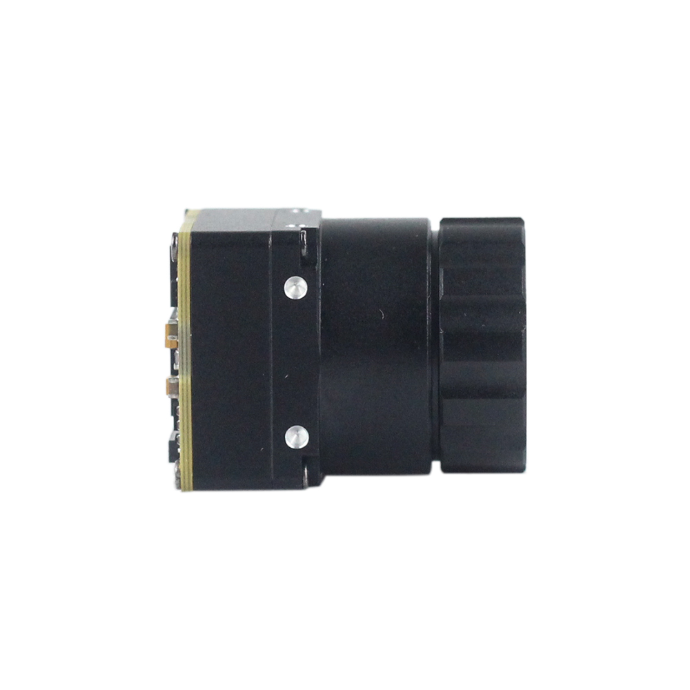
Uncooled LWIR USB Mini 640*512 Thermal Imaging Camera Core Module For Drones Similar To DJI
The Mini 640 uncooled infrared thermal imaging module delivers sharp, crisp image presentation in a remarkably compact, low-cost form factor. Featuring an ultra-small footprint of 21mm × 21mm, this core module is engineered specifically for micro-gimbals and enterprise aerial integration similar to DJI Matrice platforms. It supports an expansive optical array spanning 5mm, 9mm, 13mm, 18mm, 35mm, 50mm, 75mm, 100mm, and 150mm lenses. Built to handle harsh aerial environments, it offers optional 640×480 and native 640×512 resolutions, rock-solid baseline stability, and powerful environmental adaptability.
- ✅ Form Factor: Sub-miniature 21mm × 21mm cross-section
- ✅ Resolution: 640×512 Native (640×480 selectable)
- ✅ Lens Compatibility: 5mm to 150mm Germanium optics
- ✅ System Compatibility: Plug-and-play USB and digital interfaces for enterprise UAS
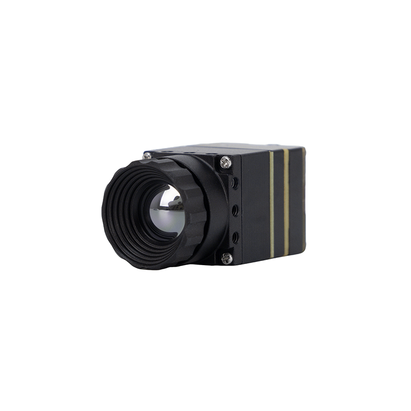
MD Series 384x288 Uncooled Infrared Thermal Camera Module
The Purpleriver MD Series thermal camera module is purpose-built for industrial-grade precision across security, structural temperature monitoring, and drone payload integration. Utilizing an advanced uncooled infrared detector with a 12μm pixel pitch, the module delivers exceptional thermal sensitivity and sharp imagery. With a compact physical footprint, plug-and-play architecture, and flexible output interfaces—including MIPI, USB, and CVBS—it guarantees rapid integration into edge computing and flight avionics systems. Backed by an engineering team drawing from the Hong Kong University of Science and Technology (HKUST) and former Huawei HiSilicon hardware specialists, the MD Series provides flexible OEM/ODM customization to meet demanding mission specifications.
- ✅ Pixel Pitch: High-density 12μm uncooled detector
- ✅ Array Resolution: 384×288 high-contrast thermal imaging
- ✅ Multi-Bus Connectivity: Native MIPI CSI-2, USB 2.0, and CVBS composite video
- ✅ Design Heritage: HKUST research & former Huawei HiSilicon semiconductor discipline
Direct Engineering Comparison: Mini 640×512 vs. MD Series 384×288
To assist systems integrators in choosing the correct core for specific payload requirements, the following table summarizes structural, optical, and electrical parameters:
| Parameter | Mini 640×512 OEM Core Module | MD Series 384×288 Industrial Module |
|---|---|---|
| Thermal Core Image |
|
|
| Product Page Reference | Mini 640 Uncooled LWIR Core | MD Series 384×288 LWIR Module |
| Native Resolution | 640 × 512 (Optional 640 × 480 Mode) | 384 × 288 |
| Pixel Pitch | 12µm | 12µm |
| Physical Dimensions | 21mm × 21mm (Bare Module Footprint) | Ultra-Compact Industrial Packaging |
| Lens Ecosystem | 5mm, 9mm, 13mm, 18mm, 35mm, 50mm, 75mm, 100mm, 150mm | Athermalized fixed-focal manual & fixed industrial optics |
| Supported Interfaces | USB (UVC compliant), MIPI, Direct UART Control | MIPI CSI-2, USB 2.0, CVBS (Composite Analog) |
| Engineering Background | Hong Kong University of Science and Technology (HKUST) Advanced Sensing | HKUST Advanced Research & Former Huawei HiSilicon Core Specialists |
| OEM/ODM Customization | Custom barrel threading, bespoke PCB geometry, FPC pinout adaptation | Firmware ISP tuning, custom hardware interface cards, radiometric tables |
| Primary Payload Targets | DJI-Class Enterprise Gimbals, Long-Range Reconnaissance, Tactical UAVs | Cost-Critical Drones, Compact Security Pan-Tilts, Thermal IoT Devices |
7. Technical Integration FAQ: Uncooled LWIR Cores for Aerial Platforms
How do you solve SWaP (Size, Weight, and Power) constraints when integrating thermal modules into micro-drones?
What interfaces are supported, and how is software integration handled across embedded SBCs?
Can uncooled LWIR camera modules maintain radiometric accuracy during rapid outdoor temperature swings?
📚 References & Further Reading
- Industry Standard: Microcontroller platform automation via Arduino.
- Industry Standard: Industrial optomechanical components and thermal manufacturing by KUYANG.
- Related Guide: Explore deep UAV autonomous vision architectures in our guide on thermal imaging modules for drone integration and edge AI.
- Related Guide: Examine optical focal plane array scaling in our technical review of commercial infrared thermal imaging solutions and high-resolution modules.
- Related Guide: Multi-language operational parameters and optical setups in our Arabic guide to 640×512 35mm thermal camera module configurations.