Thermal Camera Module Price Guide: Cost Factors, Specs & OEM Sourcing
2026年9月11日
Engineering Guide: Specifying and Purchasing High-Performance OEM Thermal Camera Cores
Integrating Long-Wave Infrared (LWIR) sensing into mission-critical platforms—such as uncrewed aerial vehicle (UAV) stabilized gimbals, autonomous mobile robots (AMRs), automated optical inspection (AOI) lines, and handheld optronics—requires an analytical design methodology fundamentally distinct from standard visible-spectrum imaging. When optical, aerospace, and systems engineers set out to buy thermal camera core modules, they are not simply selecting an off-the-shelf consumer sensor; they are specifying an electro-optical engine that must rigorously balance SWaP-C (Size, Weight, Power, and Cost), detector solid-state physics, microbolometer thermal time constants, and deterministic low-latency video pipelines under dynamic environmental conditions.
A single miscalculation in sensor specification cascades across an entire embedded hardware architecture. Underestimating the Noise Equivalent Temperature Difference (NETD) degrades automated edge-segmentation algorithms in low-thermal-contrast environments, such as during maritime search-and-rescue or over overcast terrains. Specifying an inappropriate hardware interface can overwhelm host system bus bandwidth or introduce unmanageable glass-to-glass latency, while selecting an improper optical f-number significantly compromises system-level spatial resolution and target Detection, Recognition, and Identification (DRI) metrics. This technical guide delivers the mathematical, physical, and integration criteria necessary to evaluate, select, and procure enterprise-grade uncooled microbolometer cores (featuring 640×512 and 384×288 native resolutions) for advanced industrial, robotic, and aerospace deployments.
Table of Contents
- 👉 1. Fundamental Core Architecture: How OEM LWIR Modules Operate
- 👉 2. Critical Evaluation Metrics When You Buy a Thermal Camera Core
- 👉 3. Optical Engineering: Lens Selection, Germanium Optics, and DRI Ranges
- 👉 4. Hardware Interfaces, Embedded Processing, and System Integration
- 👉 5. Comparative Product Showcase: Enterprise-Grade 640 & 384 LWIR Cores
- 👉 6. Application-Specific Selection Matrix (Drones, Vision, Optronics)
- 👉 7. Procurement, Tier-1 Sourcing, and Lifecycle Considerations
- 👉 8. Frequently Asked Questions (Deep-Dive Technical FAQ)
1. Fundamental Core Architecture: How OEM LWIR Modules Operate
An OEM thermal imaging core converts incident radiant electromagnetic flux within the Long-Wave Infrared spectrum (typically spanning 8μm to 14μm) into linear 14-bit or 16-bit digital radiometric data frames and standardized digital or analog video streams. The functionality of modern uncooled thermal modules depends on three tightly coupled subsystems: the focal plane array (FPA), the readout integrated circuit (ROIC), and the onboard digital signal processor (typically an FPGA or dedicated low-power ASIC engine).
Incident thermal radiation emits from target bodies according to Planck’s Radiation Law, transmitting through the atmosphere and through an anti-reflective coated optical lens to focus directly onto the microbolometer matrix. The focal plane array absorbs this optical power, which alters the electrical resistance of each pixel membrane in direct proportion to its temperature. The integrated ROIC samples these resistive deviations row-by-row, digitizing the faint microvolt variations via onboard analog-to-digital converters (ADCs). The digital telemetry is then fed into an onboard FPGA pipeline responsible for non-uniformity correction (NUC), dead pixel replacement (BPR), spatial filtering, and dynamic range compression before presentation over external buses.

From a thermal physics perspective, each individual microbolometer pixel functions as a delicate thermodynamic structure suspended in a local vacuum. When incident photon flux strikes the absorbing layer (often composed of silicon nitride combined with a thin resistive metal film), the absorbed power raises the active membrane temperature relative to the underlying silicon substrate. The fundamental heat transfer equation governing each microbolometer element is expressed as:
Cth · (dT/dt) + Gth · ΔT = η · Pin
Here, Cth represents the pixel thermal heat capacity, Gth is the thermal conductance of the narrow micro-machined support legs, η is the absorption efficiency across the 8μm to 14μm spectral band, and Pin represents incident radiative power. The thermal time constant τth = Cth / Gth determines how rapidly the detector responds to scene transitions. If a target moves faster than this physical time constant permits, individual pixels cannot cool down before the subsequent frame integration cycle begins, causing noticeable tailing and modulation transfer function (MTF) degradation.
Microbolometer Physics: Vanadium Oxide (VOx) vs. Amorphous Silicon (α-Si)
At the foundation of uncooled thermal engineering is the active material utilized within the microbolometer bridge membrane. Each pixel consists of an absorbing plate suspended above an underlying silicon substrate by micro-machined silicon nitride legs that provide thermal isolation within an evacuated, hermetically sealed cavity.
- ✅ Vanadium Oxide (VOx): VOx represents the industry benchmark for commercial, industrial, and defense-grade thermal systems. The material exhibits a high Temperature Coefficient of Resistance (TCR), typically running between -2% to -3% per Kelvin at 300K, combined with exceptionally low 1/f (flicker) electronic noise. This elevated TCR enables VOx sensors to achieve industry-leading thermal sensitivity (NETD ≤ 30mK to 40mK) alongside rapid thermal time constants (τ ≈ 8ms to 12ms). As a direct result, VOx FPAs deliver sharp imagery with minimal motion blur, making them the preferred choice for fast-moving airborne gimbals and autonomous navigation.
- ⚙️ Amorphous Silicon (α-Si): In contrast, amorphous silicon detectors can be manufactured directly using standard CMOS semiconductor lithography lines, which lowers raw wafer production costs. However, α-Si exhibits higher intrinsic 1/f noise, lower electrical conductivity, and lower structural TCR values (frequently hovering around -1.5% to -1.8%/K). Consequently, α-Si sensors often exhibit higher baseline NETD figures (>50mK) and slower thermal time constants (τ > 14ms). Downstream signal processing engines must apply heavy temporal filtering to suppress baseline noise, which introduces noticeable ghosting and edge latency when tracking fast-moving targets.
Pixel Pitch Dynamics: The Shift from 17μm to 12μm Wafer-Scale Packaging
Over the past decade, the infrared industry has transitioned from legacy 17μm pixel architectures to 12μm wafer-scale packaging (WSP). This reduction in pixel pitch yields major physical and optical advantages:
- ✅ Optical Aperture and Payload Footprint: The physical diagonal of a 640×512 sensor array drops from 13.93mm on a 17μm pitch down to just 9.83mm on a 12μm pitch. Because the focal length required to achieve an equivalent Field of View (FOV) scales linearly with the detector diagonal, a 12μm core requires a lens with an optical focal length roughly 30% shorter than that of a 17μm core. The corresponding clear optical aperture of the lens shrinks proportionally, reducing the physical mass and volume of expensive monocrystalline Germanium optics by up to 50%. This enables developers to engineer ultra-miniature systems, such as 21mm × 21mm form-factor modules that fit comfortably within compact drone payloads.
- ⚙️ Diffraction Limits and Optical Tolerance: While 12μm geometries enable ultra-compact SWaP-C envelopes, they push the optical imaging train directly against the physical diffraction limits of LWIR radiation (λ ≈ 10μm). For an optical system operating at f/1.0, the central Airy disk diameter is calculated as:
dAiry = 2.44 × λ × f/# ≈ 2.44 × 10μm × 1.0 = 24.4μm
Because the central diffraction spot spans slightly more than two 12μm pixels, optical engineers must specify precision-machined, aspheric Germanium or Chalcogenide lenses characterized by low wave-front error and minimal chromatic aberration to prevent optical crosstalk and preserve dynamic image contrast.
Non-Uniformity Correction (NUC): Mechanical Shutter vs. Shutterless Algorithms
Due to minute semiconductor manufacturing variances across the microbolometer matrix, each pixel possesses a distinct baseline resistance and thermal response curve. Furthermore, internal self-heating and changing ambient thermal conditions cause the baseline output of the pixels to drift non-linearly over time. Without continuous mathematical correction, the thermal image degrades into severe spatial noise, colloquially known as "fixed-pattern noise" (FPN). Modern cores counteract this through two mechanisms:
- ⚙️ Electromechanical Shutter Calibration (1-Point NUC): An onboard miniature solenoid periodically swings a blackened, high-emissivity mechanical flag in front of the FPA for 100ms to 300ms. By viewing an optically uniform thermal surface, the onboard processor calculates updated offset coefficients for every individual pixel, resetting the array's baseline uniformity. While this technique guarantees optimal radiometric accuracy and low spatial noise, the physical shutter mechanism introduces moving parts prone to mechanical wear, while momentarily pausing the live digital video stream.
- ✅ Shutterless Scene-Based Non-Uniformity Correction (SBNUC): For high-vibration aerospace, continuous tracking, or weapon-sight platforms where video interruption cannot be tolerated, high-end DSP engines implement advanced SBNUC algorithms. SBNUC continuously tracks high-frequency spatial deviations across consecutive image frames, utilizing natural scene motion to separate true target thermal signatures from sensor fixed-pattern drift. However, SBNUC architectures require substantial FPGA compute resources and can occasionally create ghosting artifacts if the thermal camera remains static while viewing a stationary scene with high thermal gradients.
Mathematically, linear two-point non-uniformity correction operates on raw digital counts Xij generated by the pixel at row i and column j according to:
Yij = Gij · Xij + Oij
Where Gij represents the individual gain coefficient and Oij represents the real-time offset term. Because the offset vector migrates as ambient chassis temperatures fluctuate, the embedded FPGA must continuously interpolate offset lookup tables based on internal thermistor telemetry placed directly on the focal plane substrate.
2. Critical Evaluation Metrics When You Buy a Thermal Camera Core
When selecting and sourcing OEM thermal camera hardware, systems engineers must evaluate four core electro-optical and operational metrics to confirm operational fit:
Noise Equivalent Temperature Difference (NETD)
Noise Equivalent Temperature Difference defines the minimum temperature variation across an object that generates a signal-to-noise ratio (SNR) of unity at the detector output. Measured in milliKelvins (mK), NETD serves as the primary figure of merit for microbolometer sensitivity. Industrial-grade modules exhibit ratings between ≤30mK and ≤40mK, while entry-level commercial units typically test above 50mK. An NETD of 35mK means the core can resolve scene variations as small as 0.035°C.
When evaluating vendor data sheets, engineers must audit the exact test conditions under which the NETD was measured. Sensitivities quoted without specifying the optical f-number (typically f/1.0), the ambient test temperature (typically 300K / 27°C), and the target frame rate (e.g., 50Hz) can be misleading. Operating an NETD ≤ 40mK core behind an f/1.4 lens, for example, cuts the flux reaching the detector by half, increasing effective system noise to nearly 80mK according to the inverse-square law of the f-number:
NETDsystem ∝ (f/#)2 · (1 / τoptics)
Frame Rate Regimes and Global Dual-Use Export Controls
The temporal frame rate of an infrared core dictates its target-tracking capabilities and directly determines its international export classification:
- ⚙️ ≤ 9Hz Thermal Cores: Slow-frame-rate modules are generally exempt from strict multilateral defense export controls and can be acquired for commercial, civil, and consumer integration with straightforward documentation. However, a 9Hz temporal refresh rate is inadequate for closed-loop drone stabilization, high-speed automated sorting, or vehicle piloting, as camera movement at 9fps induces noticeable target judder, frame lag, and motion smear.
- ✅ 25Hz / 30Hz / 50Hz / 60Hz High-Speed Cores: High-frame-rate cores are required for real-time robotic perception, stabilized airborne tracking gimbals, search and rescue, and optronic scopes. These modules deliver smooth motion representation and ultra-low glass-to-glass latency (<30ms). However, procurement of thermal cores running at ≥25Hz is strictly regulated under dual-use export control regimes, including the Wassenaar Arrangement, United States International Traffic in Arms Regulations (ITAR) / Export Administration Regulations (EAR), and equivalent European Union regulations. Buyers must execute End-User Certificates (EUC) confirming non-proliferation compliance before procurement contracts can be fulfilled.
Radiometric Data Output vs. Qualitative Imaging
Procurement teams must distinguish between qualitative thermal imaging cores and quantitative radiometric measurement cores:
- ⚙️ Qualitative (Imaging-Only) Cores: The embedded FPGA converts the high-dynamic-range 14-bit microbolometer signal directly into an 8-bit standard output (YUV422 or RGB24) via adaptive dynamic range algorithms (such as Digital Detail Enhancement - DDE, local contrast optimization, and histogram equalization). The camera outputs an aesthetically sharp visual image tailored for human display systems, but discards raw sensor voltage values. True target temperatures cannot be extracted from the video stream.
- ✅ Quantitative (Radiometric) Cores: The module outputs a linear digital signal (typically 14-bit or 16-bit digital words per pixel) alongside or interleaved with the visual video stream. Each digital level (Digital Number - DN) maps directly to radiant energy or temperature via calibrated sensor lookup tables (LUTs) factoring in internal core temperatures. Radiometric output is essential for automated predictive maintenance, electrical substation inspection, wildland fire perimeter mapping, and automated machine vision. Systems engineers looking for deep architectural guidance on digital streaming buses should study this guide to high-performance MIPI thermal modules.
3. Optical Engineering: Lens Selection, Germanium Optics, and DRI Ranges
Because silicate-based optical glass is completely opaque to electromagnetic radiation within the 8μm to 14μm waveband, thermal camera cores require specialized transmissive optical materials combined with high-performance anti-reflective thin-film coatings.
Optical Substrates: Monocrystalline Germanium vs. Chalcogenide Glass
Two primary optical substrates dominate the LWIR market:
- ✅ Monocrystalline Germanium (Ge): Germanium possesses an exceptionally high refractive index (n ≈ 4.0 at 10μm), allowing optical engineers to design lenses with shallow surface curvatures, minimal spherical aberrations, and high optical power within compact physical dimensions. Germanium is mechanically robust and suited for harsh airborne environments. However, pure Germanium suffers from thermal runaway: as ambient optical temperatures surpass 60°C, free-electron absorption increases exponentially, causing the substrate to lose transparency. Consequently, external surfaces must feature durable Anti-Reflective (AR) or Diamond-Like Carbon (DLC) hard coatings to survive rain erosion, dust abrasion, and saline atmosphere.
- ⚙️ Chalcogenide Glass (e.g., GASIR): Chalcogenide materials consist of synthetic compounds containing sulfur, selenium, or tellurium. Unlike Germanium, Chalcogenide glasses can be molded via precision glass pressing rather than ground and polished with single-point diamond turning (SPDT). This allows cost-effective production of complex aspheric lens designs at volume. Furthermore, Chalcogenide exhibits an exceptionally low thermo-optic coefficient (dn/dT), simplifying the engineering of passively athermalized lens assemblies that stay in focus from -40°C to +85°C without active motor compensation.
DRI Range Calculations (Johnson’s Criteria Applied to 12μm Cores)
To project real-world target acquisition ranges for security, defense, and drone search missions, optical engineers employ Johnson’s Criteria. The spatial frequency requirements across a target’s critical dimension (traditionally a human target scaled to 1.8m × 0.5m with a 0.75m critical dimension, or a standard vehicle of 2.3m × 2.3m) are defined as:
- ⚙️ Detection (1.5 cycles / ~2 pixels on target): The observer can determine that an object of interest is present in the scene.
- ⚙️ Recognition (6.0 cycles / ~8 pixels on target): The observer can classify the target type (e.g., differentiating a human from an animal, or a truck from a passenger vehicle).
- ⚙️ Identification (12.0 cycles / ~16 pixels on target): The observer can identify specific details (e.g., identifying a commercial pickup versus an armed technical vehicle).
The Instantaneous Field of View (IFOV), representing the spatial angle subtended by a single physical pixel, is calculated as:
IFOV (mrad) = Pixel Pitch (p) / Lens Focal Length (f)
For a modern 12μm VOx thermal core:
- ✅ Wide-Angle Optics (f = 9mm): IFOV = 12μm / 9mm = 1.33 mrad. At an operational distance of 1,000 meters, one pixel spans 1.33 meters. This lens geometry provides an expansive field of view, ideal for short-range situational awareness, indoor mobile robotics, and localized aerial mapping.
- ✅ Telephoto Long-Range Optics (f = 75mm): IFOV = 12μm / 75mm = 0.16 mrad. At a distance of 1,000 meters, one pixel covers just 16 centimeters. This tighter spatial projection enables positive human target detection beyond 3,500 meters and vehicle identification past 2,000 meters.
When computing field DRI envelopes, systems integrators must also account for atmospheric attenuation using Beer-Lambert transmission modeling:
τatm(R) = exp(-γ · R)
Where γ is the atmospheric extinction coefficient (dominated in the LWIR spectrum by absolute humidity and water-vapor continuum absorption) and R is the distance to the target. In humid maritime environments, γ can reduce effective detection ranges by 30% to 50% compared to dry desert testing scenarios.
Optical Mounts and Mechanics
OEM cores use threaded barrel configurations to ensure optical concentricity and maintain a stable focal position under continuous shock and vibration. Standard configurations include micro-threaded mounts (e.g., M10×0.5, M12×0.5, or proprietary coarse threadings) fitted with fluoroelastomer (Viton) O-rings. These O-rings seal the optical path against environmental moisture ingress, preserving IP67-rated enclosures in airborne payloads.
4. Hardware Interfaces, Embedded Processing, and System Integration
Integrating an uncooled thermal core into host electronics requires careful matching of data transfer bandwidth, power dissipation paths, and software communication pipelines.
Digital and Analog Video Pipelines
Thermal camera cores generally output video and telemetry over one or more of the following standard interfaces:
- ✅ USB 2.0 / USB 3.0 (UVC Architecture): Cores featuring USB endpoints implement the USB Video Class (UVC) protocol, enabling plug-and-play streaming into Linux, Windows, and ROS (Robot Operating System) hosts without requiring custom kernel drivers. The core streams 8-bit visual YUV/RGB frames alongside 14-bit uncompressed Y16 radiometric buffers over bulk transfer endpoints, simplifying software development.
- ⚙️ MIPI-CSI2 (Mobile Industry Processor Interface): For lightweight embedded hardware running edge-AI processors (such as the NVIDIA Jetson Orin series or Rockchip RK3588), MIPI-CSI2 is the preferred interface. By routing differential serial clock and data lanes directly into the host processor's Image Signal Processing (ISP) pipeline, MIPI bypasses USB protocol conversion latency, cuts hardware component counts, and reduces power consumption.
- ⚙️ Analog Composite Video (CVBS - NTSC/PAL): Analog composite video remains popular in specialized airborne FPV systems, legacy target turrets, and real-time flight controls. Because CVBS output bypasses OS digital frame buffers, it delivers ultra-low end-to-end latency (≤10ms), preventing control loop instability during high-speed manual drone piloting.
Interfacing with Embedded Single-Board Computers and Microcontrollers
Modern autonomous platforms rely on split processing architectures to handle imaging pipelines and hardware controls efficiently:
- ✅ Single-Board Computers (SBCs): Systems integrators frequently pair USB or MIPI thermal modules with embedded platforms like the Raspberry Pi to execute deep-learning object classifiers (e.g., YOLOv8-tiny) or perform automated thermal segmentation routines directly at the edge.
- ⚙️ Microcontrollers: For auxiliary tasks—such as sending NUC calibration pulses, adjusting motorized focus mechanisms, or reading ambient temperature sensors—engineers frequently link an Arduino or comparable ARM Cortex-M microcontroller to the core’s UART or I²C control interfaces. For a detailed exploration of compact edge implementations, read our overview of low-power thermal camera modules for localized payloads.
Thermal Dissipation and Power Integrity
Because microbolometers measure microscopic changes in pixel temperature, they are sensitive to thermal fluctuations within the camera chassis itself. Poor mechanical heat-sinking creates asymmetric thermal gradients across the core housing, resulting in non-uniform spatial drift, localized shading artifacts, and frequent NUC shutter cycles.
To avoid these issues, engineers must mechanically couple the core’s primary chassis interface to an external aluminum heat sink using high-conductivity thermal gap pads (≥3.0 W/m·K). Furthermore, because ROIC readout noise correlates directly with power rail stability, system power supplies must be decoupled using low-noise Low Dropout (LDO) linear regulators. Power rail ripple must stay below 20mV peak-to-peak to prevent visible banding across the thermal image.
5. Comparative Product Showcase: Enterprise-Grade 640 & 384 LWIR Cores
When preparing to buy thermal camera core modules, systems engineers must evaluate verified commercial hardware against their project’s SWaP-C requirements. Below are two industry-tested LWIR cores designed for integration into aerial gimbals, machine vision systems, and autonomous robotic platforms.

Uncooled LWIR USB Mini 640*512 Thermal Imaging Camera Core Module
Designed specifically for UAV stabilized gimbals (comparable to enterprise DJI payload architectures), advanced thermal sights, and high-performance robotic tracking, this mini uncooled infrared thermal imaging core delivers sharp imagery within an ultra-compact footprint. Measuring just 21mm × 21mm, it combines high thermal sensitivity (≤40mK) with versatile optical options to support applications ranging from wide-angle aerial mapping to long-distance reconnaissance.
- ✅ Native Resolution: 640 × 512 (640 × 480 selectable operating mode)
- ✅ Detector Type: High-sensitivity Uncooled VOx Microbolometer (12μm pixel pitch)
- ✅ Thermal Sensitivity: NETD ≤ 40mK @ f/1.0, 300K
- ⚙️ Extensive Lens Portfolio: 5mm, 9mm, 13mm, 18mm, 35mm, 50mm, 75mm, 100mm, and 150mm focal lengths
- ✅ Form Factor: Ultra-miniature 21mm × 21mm footprint for constrained enclosures
- ⚙️ Connectivity: USB 2.0 (UVC stream + full 14-bit radiometric raw telemetry) with UART serial control
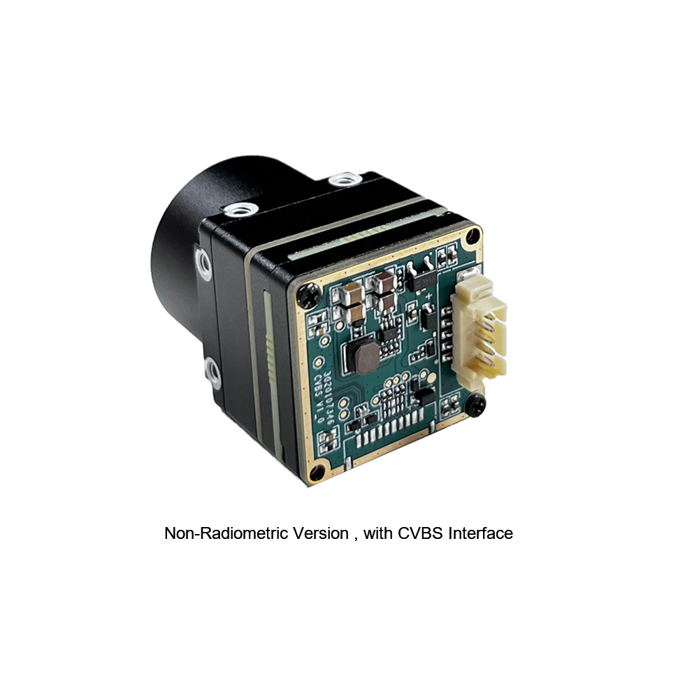
Uncooled Mini 384*288 Thermal Camera Module For Drones
The MINI series 384×288 infrared thermal module provides a balanced, small-form-factor solution for online temperature measurement and continuous industrial process monitoring. Utilizing high-performance detectors and low-latency processing, this core is engineered for machine vision inspection, factory safety systems, electrical switchgear maintenance, and lightweight drone payloads requiring reliable radiometric thermal imaging.
- ✅ Native Resolution: 384 × 288 active pixels
- ✅ Thermal Imaging Engine: High-precision uncooled focal plane array with stable drift compensation
- ⚙️ Precision Radiometry: Online industrial temperature measurement with point, line, and area analysis
- ⚙️ Interface Versatility: Direct analog CVBS composite video alongside digital outputs for display or transmission
- ✅ Primary Target Applications: Machine vision, automated safety inspection, equipment maintenance, and small aerial drones
Direct Engineering Comparison Table
| System Parameter | Mini 640×512 LWIR Module | Mini 384×288 LWIR Module |
|---|---|---|
| Active Pixel Matrix | 640 × 512 (Optional 640 × 480) | 384 × 288 |
| Physical Dimensions | Ultra-miniature (21mm × 21mm × 21mm) | Compact MINI Series Envelope |
| Available Lens Lineup | 5, 9, 13, 18, 35, 50, 75, 100, 150mm | Standard MINI Series Optics (Fixed / Focusable) |
| Digital & Analog I/O | USB 2.0 (UVC + Y16 Radiometric) + UART | CVBS Composite Video + USB + UART |
| Thermal Sensitivity (NETD) | ≤ 40mK @ f/1.0, 300K | ≤ 40mK @ f/1.0, 300K |
| Target Integration Envelopes | DJI-class stabilized gimbals, advanced long-range security | Machine vision inspection, automated factory monitoring, sUAVs |
6. Application-Specific Selection Matrix
Selecting between 640×512 and 384×288 resolutions requires analyzing operational requirements against target platform constraints:
1. Stabilized Drone Gimbals and Tactical UAV Payloads
For aerial platforms, every additional gram of payload directly reduces flight endurance. Upgrading to an ultra-compact 21mm × 21mm 640×512 module provides high spatial resolution (327,680 individual pixels) without exceeding payload weight limits. In utility inspections (such as scanning high-voltage transmission lines or solar farms), this elevated pixel count lets drone pilots operate at a safe standoff distance while resolving fine thermal anomalies, such as failing cells or high-resistance connectors.
- ✅ Recommended Core: Mini 640×512 LWIR Module (VOx, 12μm).
- ⚙️ Key Optical Pairing: 13mm to 35mm athermalized Germanium optics with DLC external coating.
- ✅ Primary Advantage: Superior DRI metrics permitting safe standoff distance while retaining sub-30ms glass-to-glass latency for gimbal stabilization loops.
2. Automated Machine Vision and Industrial Monitoring
In high-speed manufacturing, robotic cells require continuous non-contact thermal inspection to catch mechanical bearing friction, PCB thermal anomalies, and injection molding defects. The Mini 384×288 Thermal Core provides a balanced combination of high reliability, compact sizing, and accessible cost for distributed industrial monitoring networks. Its onboard radiometric processing calculates automated alarms for user-defined Regions of Interest (ROIs), passing critical alerts directly to factory programmable logic controllers (PLCs).
- ✅ Recommended Core: Mini 384×288 Thermal Camera Module.
- ⚙️ Key Optical Pairing: 9mm or 13mm wide-angle optics with standard anti-reflective coating.
- ✅ Primary Advantage: Budget-conscious multi-camera deployment across manufacturing lines with direct 14-bit radiometric data extraction over USB or CVBS.
3. Security Optronics, Handheld Monoculars, and Sights
Weapon-mounted optics, perimeter monitoring systems, and search-and-rescue monoculars demand high spatial identification metrics. Pairing a 640×512 12μm core with narrow-field-of-view Germanium lenses (such as 50mm, 75mm, or 100mm optics) provides the angular resolution needed to detect and classify human targets beyond one kilometer in zero-lux conditions, through light foliage, or in smoke-filled environments.
- ✅ Recommended Core: Mini 640×512 LWIR Module.
- ⚙️ Key Optical Pairing: 50mm, 75mm, or 100mm narrow-angle manual or motorized focus lenses.
- ✅ Primary Advantage: Sub-mrad spatial resolution resolving human profiles at distances exceeding 1,500 meters under extreme environmental temperatures (-40°C to +70°C).
7. Procurement, Tier-1 Sourcing, and Lifecycle Considerations
Procuring microbolometer cores for long-term production programs involves several operational and supply chain considerations:
- ⚙️ Wafer Supply Chain Stability: Ensure your core manufacturer maintains verified access to high-yield VOx semiconductor fabrication and raw monocrystalline Germanium. Fluctuations in raw material availability can introduce severe production delays.
- ⚙️ Radiometric Recalibration Support: Over continuous multi-year industrial or military deployments, thermal detectors can exhibit long-term baseline drift. Tier-1 suppliers provide software API suites that allow engineering teams to perform field recalibrations without having to return units to the factory.
- ✅ Software Toolkits and Driver Portability: A smooth hardware integration depends on clear, complete documentation. Ensure your core supplier provides functional Linux kernel drivers (Video4Linux2 / V4L2 compliant), comprehensive C/C++ SDKs, ROS wrappers, and detailed hardware register maps. Registered enterprise customers can download current SDK updates and firmware patches directly via their customer account portal.

8. Frequently Asked Questions (Deep-Dive Technical FAQ)
Are OEM thermal camera cores from specialized manufacturers worth buying compared to consumer dongles?
In contrast, specialized OEM thermal camera cores (such as the Purpleriver Mini 640 and 384 platforms) feature uncooled Vanadium Oxide (VOx) focal plane arrays with thermal sensitivity ≤40mK, ultra-compact 21mm × 21mm form factors, and deterministic sub-30ms hardware latency pipelines. These cores provide interchangeable, anti-reflective coated Germanium optics (with focal lengths up to 150mm), raw 14-bit linear radiometric output streams, and standard industrial interfaces (USB, CVBS, UART) that allow direct embedded integration into systems running on platforms like the Raspberry Pi or NVIDIA Jetson.
Can I replace or upgrade the thermal core inside an existing scope or drone gimbal?
The ultra-miniature 21mm × 21mm cross-section of the Mini 640 core allows it to drop into tight gimbal assemblies previously designed for older, bulkier sensor platforms. Integrators must verify that the host gimbal slip ring supports the core's chosen video format (such as low-latency CVBS analog composite or uncompressed USB UVC digital video). Additionally, command mapping for Non-Uniformity Correction (NUC) and color palette switching can be adapted using straightforward UART serial commands, allowing developers to upgrade legacy systems to modern 640×512 resolution without re-engineering the outer housing.
What should I evaluate before deciding to buy a thermal camera core for a DIY or commercial build?
1. Resolution and Pixel Pitch: Assess whether a 384×288 array meets your spatial resolution requirements, or if a high-definition 640×512 array is necessary to achieve your required Detection, Recognition, and Identification (DRI) metrics. A 12μm pixel pitch is generally preferable, as it significantly reduces overall lens volume and weight.
2. Optical Path and Aperture: Ensure your lens selection matches the core's microbolometer format and provides an appropriate f-number (ideally f/1.0 to f/1.2) to maintain rated thermal sensitivity without introducing optical vignetting.
3. Electrical and Software Integration: Verify that the core's output interface matches your onboard computing architecture. While USB UVC simplifies integration on single-board computers, direct MIPI or analog CVBS links may be required to minimize video latency.
4. Export Regulations: Determine whether your application requires a high-frame-rate (≥25Hz) module, and ensure your organization has the necessary compliance documentation in place to fulfill export control requirements.
📚 References & Further Reading
- Industry Standard Embedded Compute: Raspberry Pi Foundation Embedded Processing Systems
- Hardware Control Platforms: Arduino Microcontroller Architecture and Interfaces
- Related Guide (Russian): Обзор низкопотребляющих модулей тепловизионных камер
- Related Guide (Arabic): دليل وحدات الكاميرا الحرارية عالية الأداء عبر واجهة MIPI