Uncooled Thermal Module Solutions: High-Res AI & OEM Integration Guide
2026年7月30日
Top IR Camera Module Solutions for Drones & Embedded AI: OEM Integration Guide
2026年7月31日
Infrared Thermal Sensor Module Guide: Selecting High-Res IR Modules for Edge AI & Drones
Look, dropping high-resolution thermal vision into a tiny quadcopter gimbal, an autonomous rover, or an industrial IoT rig isn't a walk in the park. Hardware engineers constantly balance strict SWaP (Size, Weight, and Power) limits against demanding signal-to-noise ratios (SNR) and high temporal frame rates. Standard visual-spectrum cameras are useless in total darkness, dense smoke, heavy atmospheric fog, and blinding solar glare. That’s why uncooled Long-Wave Infrared (LWIR) OEM camera modules are standard gear for real-world missions. But here's the deal: grabbing a raw 14-bit thermal data stream takes a solid physical interface pipeline, tight optomechanical design, and smart onboard signal conversion before your Edge AI accelerator can even start processing frames.
If you're building autonomous navigation systems, payload gimbals, or industrial predictive maintenance setups, you need to evaluate detector physics, focal length choices, image pipeline latencies, and transport buses. Choosing between a direct, high-bandwidth raw pixel interface like MIPI-CSI2 and a networked H.264/H.265 RTSP stream over RJ45 Ethernet impacts both your PCB board layout and your Linux driver stack. Selecting the right infrared thermal sensor module comes down to understanding the physics of microbolometers, electronic backends, optical physics, and how to get data quickly into your computer vision models.
Table of Contents
- 👉 1. Core Architecture of LWIR Microbolometer Sensors
- 👉 2. Thermal Signal Pipelines: ASIC vs. FPGA Implementations
- 👉 3. Interface Protocols for Embedded Integration
- 👉 4. Optics, Germanium Coatings & DRI Distance Calculations
- 👉 5. Edge AI & Computer Vision Integration
- 👉 6. Product Comparison & Industrial Specifications
- 👉 7. Frequently Asked Questions (FAQ)
1. Core Architecture of LWIR Microbolometer Sensors
VOx Uncooled Focal Plane Arrays (FPAs)
At the center of modern thermal imaging is the uncooled Vanadium Oxide (VOx) microbolometer Focal Plane Array (FPA). Unlike legacy cooled photon detectors that require power-hungry Stirling cryocoolers to pull operating temperatures down to 77 Kelvin (-196°C), uncooled VOx sensors detect infrared energy using thermal absorption and resistance shifts. Radiation in the 8–14 μm spectrum passes through specialized lens assemblies and strikes microscopic micro-bridge structures suspended over a silicon Readout Integrated Circuit (ROIC). Each pixel absorbs LWIR energy, causing a small temperature rise that shifts the electrical resistance of the VOx thin film in a predictable curve.
In the shop, we almost always recommend VOx over amorphous Silicon (a-Si) for serious drone and defense platforms. VOx gives you a much higher Temperature Coefficient of Resistance (TCR) and a lower intrinsic noise floor. Higher TCR means better thermal sensitivity, allowing the core to cleanly separate fine thermal details across terrain, structural walls, or electrical gear. Each micro-bridge structure sits suspended over the silicon substrate on micro-machined support legs inside a vacuum-sealed cavity. This vacuum isolation prevents thermal bleed to adjacent pixels and keeps response times fast enough for real-time video.
Microbolometer Sensor Signal Processing Sequence
- ⚙️ Thermal Photon Capture: Radiated thermal energy in the LWIR band (8–14 μm) enters the antireflective lens system.
- ⚙️ Micro-Bridge Absorption: Incoming thermal radiation heats suspended Vanadium Oxide (VOx) pixel membranes.
- ⚙️ Resistance Shift: The thermal differential changes the micro-bridge's electrical resistance proportionally to target thermal flux.
- ⚙️ ROIC Digitization: The underlying Silicon ROIC reads this resistance variance and outputs a clean 14-bit digital raw stream.
Pixel Pitch and Spatial Resolution Dynamics
Sensor engineering has pushed detector pixel pitch down from older 17 μm designs to modern 12 μm (and cutting-edge 10 μm) footprints. Shrinking pixel pitch brings massive practical gains when designing compact UAV gimbals and tight robotic payloads:
- ✅ Optics Volume Reduction: A 12 μm pitch detector requires a smaller optical focal length to yield the exact same Field of View (FOV) as a 17 μm sensor. That cuts down total lens glass, barrel weight, and gimbal motor strain.
- ✅ Higher Array Density: Engineers can cram high-res arrays (640×512 or 1280×1024) into tight sensor dies that fit small, weight-sensitive gimbals.
- ⚠️ Diffraction Management: Keep in mind that as pixels shrink toward thermal wavelengths (λ ≈ 10 μm), optical design must strictly prevent optical diffraction blur from washing out your image.
Noise Equivalent Temperature Difference (NETD) & Sensitivity
Thermal sensitivity is measured as Noise Equivalent Temperature Difference (NETD), expressed in millikelvins (mK). NETD is the signal-to-noise benchmark where the signal generated by a temperature gradient equals the camera's internal noise floor:
NETD = Vn / (∂Vs / ∂T)
Where Vn is the RMS noise voltage and ∂Vs / ∂T is the detector responsivity slope. In practice, an infrared thermal sensor module with an NETD under 30 mK renders sub-degree temperature changes cleanly. That performance is vital if you're trying to spot missing insulation, early bearing failures, tiny fluid leaks, or human targets hidden in low-contrast brush. Modules with poor NETD rating (≥ 50 mK) spit out noisy, grainy frames in uniform thermal environments, causing downstream Convolutional Neural Networks (CNNs) to drop target detection confidence. For deeper technical background on electromagnetic theory, see the Wikipedia Infrared Imaging manual.
2. Thermal Signal Pipelines: ASIC vs. FPGA Implementations
The raw digital data coming directly off a microbolometer ROIC is non-linear, shows pixel-to-pixel non-uniformities, and drifts as ambient die temperatures swing. Turning that raw 14-bit data stream into crisp thermal image feeds requires real-time hardware signal processing right on the module core board.
Real-Time Thermal Image Processing Pipeline Stages
- ⚙️ 14-Bit Raw Microbolometer Stream: Unprocessed digitizer values collected straight from the ROIC die.
- ⚙️ Non-Uniformity Correction (NUC): Calibrates gain and offset variances across every individual micro-bridge pixel.
- ⚙️ Blind Pixel Replacement (BPR): Maps dead microbolometer elements and interpolates missing pixels using neighbor matrices.
- ⚙️ Digital Detail Enhancement (DDE): Filters out spatial high-frequency details to sharpen edges and object boundaries.
- ⚙️ Dynamic Range Compression (DRC) & AGC: Maps wide 14-bit radiometric ranges into clean 8-bit visual streams (256 grayscales).
Onboard Hardware Enhancement Algorithms
To convert raw infrared energy into actionable computer vision input, internal processors run several real-time mathematical operations:
- Non-Uniformity Correction (NUC): Every microbolometer bridge has slight manufacturing variances. NUC applies pre-calibrated gain and offset correction matrices to equalize pixel responses across varying ambient temperatures.
- Shutterless Calibration / Automatic Gain Control (AGC): Modern drone cores use shutterless software NUC routines to eliminate physical mechanical shutter clicks during flight, keeping video streams continuous without freezing mid-flight.
- Digital Detail Enhancement (DDE): DDE separates subtle high-frequency spatial components (like thin wires, fence lines, and vehicle edges) from broad background gradients. It boosts fine structural edges without blowing out scene highlights.
- Dynamic Range Compression (DRC): Compresses wide 14-bit thermal dynamic ranges down to standard 8-bit grayscale values (0–255), tuned for human monitoring displays and low-power AI inference models.
Power & Latency Trade-offs: Dedicated ASIC vs. FPGA
Choosing your hardware core architecture comes down to a balance between Field Programmable Gate Array (FPGA) customization and Application-Specific Integrated Circuit (ASIC) efficiency.
| Architecture Metric | Custom FPGA Implementation | Dedicated Onboard ASIC Module |
|---|---|---|
| Power Consumption | High (2.5 W - 5.0 W) | Ultra-Low (< 1.2 W) |
| Thermal Dissipation | High output requiring dedicated heat sinks | Minimal passive thermal dissipation required |
| Boot Time | Bitstream loading delay (3 - 8 seconds) | Near-instantaneous (< 1.5 seconds) |
| Physical Footprint | Bulkier multi-chip or dual-board stack | Ultra-compact single-board footprint |
| Cost Profile | High per-unit silicon cost | Optimized mass-production unit economics |
In the field, opting for an ASIC-driven module provides predictable frame rates, minimal video lag, and an exceptionally low thermal signature. For a deeper breakdown on thermal design standards, check out our report on Enterprise-Grade Manufacturing & Testing Capabilities.
3. Interface Protocols for Embedded Integration
Hooking a thermal camera core into host processor boards requires matching hardware protocols with your target bandwidth, processing overhead, and physical cable limits.
MIPI-CSI2 Interface
High-speed point-to-point interface. Directly streams raw uncompressed pixels into host processor memory using Direct Memory Access (DMA). Zero encoder delay, latency under 5 ms. Perfect for Jetson Orin and Raspberry Pi builds.
RJ45 / RTSP Network
Onboard H.264/H.265 encoders pipe RTSP IP video streams over standard Ethernet cables. Ideal for tethered drones, long wire runs, and IP security setups.
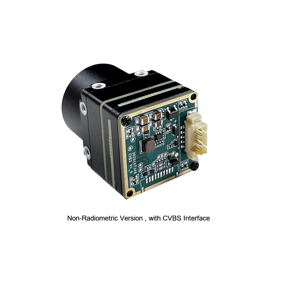
CVBS Analog & Serial
Legacy composite analog video streams instantly to ground station monitors or FPV transmitters. Separate TTL UART/RS485 ports handle serial control commands.
MIPI-CSI2 (Mobile Industry Processor Interface)
MIPI-CSI2 is the top choice for zero-latency, raw pixel pipelines connecting directly to host SoCs like NVIDIA Jetson Orin, Rockchip RK3588, or Raspberry Pi Compute Modules.
- ✅ Architectural Advantages: Completely bypasses network protocol overhead and hardware compression delays; pipes raw 14-bit radiometric or pre-processed 8-bit YUV video straight into host system RAM via Direct Memory Access (DMA). Total latency stays below 5 milliseconds.
- ⚠️ Physical Limitations: Cable runs must stay extremely short—usually under 15–20 cm over flex ribbons. High susceptibility to EMI requires proper ground shielding and careful PCB traces.
Network Interfaces: RJ45 / IP / RTSP
When you're building long-distance links, distributed edge nodes, or tethered payloads, networked thermal camera modules pack embedded H.264/H.265 video compression hardware right on the core board.
- ⚙️ Transport Mechanism: Packages encoded video frames into Real-Time Streaming Protocol (RTSP) streams sent across standard RJ45 Ethernet wiring or slip-ring interconnects.
- ✅ Integration Capabilities: Offers native ONVIF support, straightforward web UI setup, and immediate streaming into enterprise Video Management Systems (VMS).
- ⚠️ Latency Profile: Adds modest encoding and decoding latency (80–150 ms depending on host buffer size), making it better suited for tethered inspection drones, static perimeter towers, and ground inspection rovers.
Legacy Analog CVBS & Serial Control Protocols
Analog Composite Video Burst Signal (CVBS) provides direct backward compatibility with analog FPV transmitters and legacy monitors. System controls operate on secondary 3.3V TTL UART or RS485 differential lines, relying on PELCO-D or hex command sets to toggle palette modes, trigger digital zoom, adjust AGC curve offsets, and fire manual NUC routines. For assistance mapping interface layouts to your platform, see our Integrated Thermal Camera Selection Guide.
4. Optics, Germanium Coatings & DRI Distance Calculations
Standard glass lenses act like solid brick walls to long-wave infrared thermal photons. Thermal optical builds require specialized semiconductor materials—primarily monocrystalline Germanium (Ge), Chalcogenide glass, or Zinc Selenide (ZnSe).
Optical Material Physics & DLC Coatings
Monocrystalline Germanium offers a refractive index (n ≈ 4.0 in the LWIR spectrum), allowing optical engineers to build high-performance, fast aperture lenses with fewer physical elements. However, raw Germanium reflects over 30% of thermal radiation at each air-to-glass interface. To maintain optical throughput, interior lens surfaces receive multi-layer Anti-Reflective (AR) coatings, while exposed front elements are treated with Diamond-Like Carbon (DLC) hard coatings.
DLC coatings protect front optics from high-velocity airborne dust, rain strikes, salt spray, and sand abrasion on moving UAVs while keeping light transmission above 92%. Germanium also exhibits thermal drift in its refractive index (∂n/∂T). To prevent focus drift across operating environments (-40°C to +80°C), industrial thermal lenses rely on passive mechanical athermalization—combining specific metal barrel alloys whose thermal expansion physically shifts lens elements to maintain precise focus automatically.
Calculating DRI Distance (Johnson's Criteria)
Calculating optical focal length requirements comes down to standard target resolution metrics defined by Johnson's Criteria. The target critical dimension must span a minimum number of pixel line-pairs:
- ⚙️ Detection: 1.5 line pairs (3 pixels) — Confirms an object is present in the scene.
- ⚙️ Recognition: 6 line pairs (12 pixels) — Classifies target class (e.g., distinguishing a person from a vehicle).
- ⚙️ Identification: 12 line pairs (24 pixels) — Identifies specific object attributes (e.g., distinguishing a pickup truck from a sedan).
The mathematical maximum range (R) is derived from this optical formula:
R = (f × H) / (p × N)
Where f is lens focal length (mm), H is physical target height (m), p is sensor pixel pitch (mm; e.g., 0.012 mm for a 12 μm sensor), and N is required resolved pixels.
DRI Distance Reference Matrix (1.8m Human Target, 12µm Pixel Pitch, 640×512 Array)
| Focal Length (f) | Field of View (FOV) | Detection Range (N=3) | Recognition Range (N=12) | Identification Range (N=24) |
|---|---|---|---|---|
| 9 mm | 48.6° × 39.7° | 450 meters | 112 meters | 56 meters |
| 13 mm | 33.8° × 27.3° | 650 meters | 162 meters | 81 meters |
| 19 mm | 23.0° × 18.5° | 950 meters | 237 meters | 118 meters |
5. Edge AI & Computer Vision Integration
Deploying detection models onto edge hardware accelerators (NVIDIA Jetson, Google Coral, Hailo-8) requires feeding preprocessed single-channel thermal arrays properly into network layers designed for visual light images.
Preprocessing Single-Channel Thermal Data
Most object detection neural networks expect standard 3-channel RGB image matrices. Infrared sensors output a single-channel 16-bit or 8-bit grayscale array representing relative radiometric temperature or thermal flux.
- Dynamic Normalization: High-temperature hotspots in otherwise cool scenes crush histogram distributions during naive min-max scaling. Using Contrast Limited Adaptive Histogram Equalization (CLAHE) via OpenCV normalizes local image contrast dynamically before passing tensors to input layers.
- Channel Duplication vs. Sensor Fusion: For standalone thermal vision networks, duplicate the single grayscale channel across 3 RGB input channels to align with pretrained network backbones. On dual-camera platforms, align and overlay thermal LWIR frames onto visual cameras using spatial homography matrices. Read more on multi-spectrum systems in our PTZ Dual-Sensor Thermal Security Systems Guide.
Quantization and Model Acceleration
To keep inference speeds above 30 FPS on low-power embedded processors, quantize object detection networks (e.g., YOLOv8-nano, MobileNet-SSD) from FP32 floating-point values down to FP16 or INT8 using TensorRT or ONNX Runtime tools. Here’s a crucial field tip: your INT8 calibration image sets must contain real target thermal frames. Calibrating thermal neural networks using visual RGB datasets ruins detection accuracy because of fundamental differences in visual textures and thermal edge characteristics.
6. Product Comparison & Industrial Specifications
Below is a detailed breakdown of two industrial-grade uncooled infrared thermal sensor module designs built for drone payloads, robotic inspection rigs, and integrated OEM platforms.
Product 1: Uncooled Infrared RJ45 CVBS RTSP IP 640*512 Module

Overview: High-resolution 640×512 thermal imaging core managed by an onboard low-power ASIC hardware processor. Features native network IP capabilities delivering encoded H.264/H.265 video, live RTSP output, and concurrent CVBS analog signals.
- ⚙️ Resolution & Pitch: 640 × 512 array density featuring a tight 12 µm pixel pitch.
- ⚙️ Spectral Response: 8 to 14 µm (LWIR band coverage).
- ⚙️ Sensitivity: NETD ≤ 40 mK at 25°C for sharp edge definition.
- ⚙️ Video Protocols: Dual RJ45 Ethernet (IP/RTSP) and direct CVBS analog channels.
- ⚙️ Control Interfaces: UART / RS485 for custom serial command logic and palette switching.
- ⚙️ Onboard Processing: ASIC-driven Auto-NUC, DDE, shutterless tuning, and digital AGC.
Product 2: Uncooled Infrared Mini2 MIPI 640*512 9mm Thermal Module

Overview: Miniaturized ultra-lightweight thermal imaging module designed explicitly for SWaP-constrained UAV gimbals and compact computer vision setups. Offers high-speed MIPI-CSI2 digital connectivity and low power draw.
- ⚙️ Resolution Options: High-res 640×512 array (also available in 384/256 options).
- ⚙️ Integrated Optics: 9 mm Athermalized Germanium lens with hard protective coating.
- ⚙️ Digital Output Interface: High-throughput MIPI-CSI2 connector for direct host system integration.
- ⚙️ Form Factor: Ultra-lightweight, single-board construction for small gimbals and rovers.
- ⚙️ Core Processing: Low-power custom hardware processing ASIC.
- ⚙️ Primary Focus: SWaP drone gimbals, embedded Edge AI nodes, and field robotics.
7. Frequently Asked Questions (FAQ)
How do I stream real-time thermal video from an infrared thermal sensor module to a Raspberry Pi or Edge AI platform?
Streaming low-latency real-time thermal video to an embedded single-board computer (SBC) like a Raspberry Pi 4/5 or NVIDIA Jetson platform depends primarily on your module's physical hardware output interface.
For high-speed real-time computer vision processing, select a module equipped with a MIPI-CSI2 digital interface. Connect the camera module directly to the SBC's ribbon cable header via a flexible printed circuit (FPC). Within the Linux kernel, configure the corresponding V4L2 driver to expose the camera device as a native video node (/dev/video0). This setup passes raw uncompressed 8-bit or 14-bit pixel tensors straight into host system memory using Direct Memory Access (DMA), achieving sub-10 millisecond glass-to-glass latencies suitable for target tracking and autonomous obstacle avoidance.
Alternatively, if your thermal sensor module utilizes an RJ45 Ethernet interface, establish an IP network link over Ethernet using static or DHCP configurations. You can then open and capture the stream directly within Python or C++ applications using OpenCV's VideoCapture API connected to the RTSP endpoint URL. To eliminate buffer delays in network streams, ensure you set low-latency flags inside OpenCV or FFmpeg pipeline parameters (e.g., setting fflags=nobuffer and max_delay=0).
Should I select a 256x192 or 640x512 infrared thermal sensor module for drones and automation?
Choosing between an entry-level resolution (256×192 or 384×288) and a high-resolution array (640×512) depends directly on your operational standoff distance, required Field of View (FOV), and target AI classification needs.
A 256×192 thermal sensor module contains 49,152 active pixels. This provides sufficient resolution for close-range industrial maintenance, HVAC duct inspections, electrical enclosure diagnostics, and basic obstacle sensing for small indoor mobile robots (AMRs). However, when deployed on an airborne UAV flying at typical safe altitudes (30 to 100 meters), a 256×192 sensor spreads its pixels across a broad ground area. This drastically reduces the pixel count across small targets (such as humans or structural defects), dropping targets below the minimum line-pair threshold needed for reliable target recognition or AI inference model accuracy.
A 640×512 thermal sensor module delivers 327,680 pixels—providing over 6.6 times the pixel density of a 256×192 module. This substantial resolution increase provides three key benefits:
1. Extended Standoff Distance: Detect, recognize, and track human targets or equipment faults at much greater distances without changing lenses.
2. Wider Area Coverage: Capture broad situational awareness while preserving fine spatial details across the entire frame.
3. Superior Computer Vision Precision: Object detection algorithms like YOLO require distinct edge profiles to make high-confidence detections. A distant target represented by a 3x3 pixel grid on a low-res camera appears as indistinct noise, whereas a 640×512 sensor renders the target across a larger pixel region, providing clear thermal edge gradients needed for automated classification.
Can these thermal sensor modules be integrated with custom OEM hardware carrier boards?
Yes, both featured thermal camera core modules are specifically engineered for custom OEM integration, embedded robotics platforms, custom PCB carrier boards, and lightweight payload gimbals. Hardware integration spans three primary layers:
1. Mechanical and Thermal Mounting: The modules feature ultra-compact single-board form factors equipped with standardized M2/M3 mounting holes. Because onboard ASIC image processors consume under 1.2 Watts, heat dissipation can be managed passively via thermal pad contact with aluminum housing enclosures, avoiding the need for heavy active cooling fans.
2. Electrical Interface Connections: Engineers can connect custom carrier boards using flexible header configurations. High-speed digital video streams can be routed directly to host SoCs via MIPI-CSI2 flat flexible cables (FFC). Alternatively, breakout board connectors provide access to Ethernet lines (RJ45), power inputs (3.3V - 5V DC), CVBS analog channels, and UART/RS485 control lines.
3. SDK and Software Driver Tools: Modules include dedicated Software Development Kits (SDKs) and configuration toolchains supporting C/C++, Python, Linux V4L2 drivers, and Windows utilities. Software APIs give development teams complete programmatic control over internal camera parameters—including changing dynamic palettes (White-Hot, Black-Hot, Rainbow), triggering Non-Uniformity Correction (NUC), configuring shutterless operations, reading die temperature telemetry, and tuning digital enhancement parameters.
📚 References & Further Reading
- Industry Standard: OpenCV Computer Vision Library
- Industry Standard: Wikipedia Infrared Imaging Fundamentals
- Related Guide: Enterprise-Grade Manufacturing & Testing Capabilities
- Related Guide: Integrated Thermal Camera Selection Guide
- Related Product: PTZ Dual-Sensor Thermal Security Systems