









True IR vs. Near-Infrared: Ultimate Guide to True Thermal Sensor Modules
2026年8月24日
1280x1024 Thermal Module: Next-Gen HD Infrared Core Integration Guide
2026年8月25日
384x288 Thermal Camera Module: The Sweet-Spot Sensor for Drones & Machine Vision
Here's the deal: shoehorning long-wave infrared (LWIR) imaging into modern embedded systems is one of the toughest balancing acts an optical or embedded engineer will ever face. You are constantly fighting the classic SWaP-C squeeze—balancing spatial resolution, thermal sensitivity, electrical power draw, optical glass weight, and your overall bill-of-materials (BOM) cost. If you go cheap with an entry-level 256x192 sensor, you quickly realize you just don't have the pixel density needed to meet strict Johnson's DRI (Detection, Recognition, Identification) criteria during field UAV runs, nor can you isolate tiny micro-shorts on densely packed circuit boards. But if you jump straight to a top-tier 640x512 microbolometer array, your mechanical and systems engineers will be dealing with massive thermal dissipation issues, chunky Germanium glass assemblies, bus latency bottlenecks, and a brutal unit cost that kills commercial viability.
That is why the 384x288 thermal camera module has become the absolute sweet spot for real-world hardware designs. Packing 110,592 active radiometric pixels—more than double what you get out of a 256x192 core—it strikes the exact balance needed for tight SWaP-C budgets. Built on modern 12μm pixel pitch Vanadium Oxide (VOx) focal plane arrays, these uncooled cores shed serious mechanical weight while delivering noise equivalent temperature differences (NETD) down below 40mK or 50mK. Whether you are bolting one onto an autonomous inspection quadcopter, packaging it into a stabilized sub-250g pan-tilt-zoom gimbal, or wiring it up to inline automated test equipment (ATE) on the factory floor, the 384x288 format delivers the clean data, bandwidth efficiency, and thermal fidelity that mission-critical industrial imaging demands.
Look across the aerospace and machine vision landscape today, and you will see engineering teams moving away from over-specified, power-hungry sensors in favor of streamlined architectures that maximize edge compute efficiency. A 384x288 sensor gives your downstream processors enough raw radiometric data to run reliable computer vision and edge AI inference without melting your power budget or demanding a heavy heatsink assembly.

In the shop, we look at the raw numbers: every extra milliamp drawn by a sensor payload cuts down drone loiter time, and every millimeter added to the lens aperture increases the torque demand on brushless gimbal motors. Choosing the right sensor format upfront is the single most critical architecture decision you will make for your thermal vision project.
Table of Contents
- 👉 1. The 384x288 Resolution Sweet Spot: Physics, Optics, and SWaP-C
- 👉 2. Optical Physics & 12μm Pixel Pitch Advantage
- 👉 3. Drone & UAV Payload Integration Architecture
- 👉 4. Machine Vision, Automation, & PCB Thermal Diagnostics
- 👉 5. Signal Pipelines & Embedded Hardware Interfaces
- 👉 6. Product Showcase & Technical Specifications Table
- 👉 7. Implementation Guide: From Prototyping to Industrial Deployment
- 👉 8. Frequently Asked Questions (FAQ)
1. The 384x288 Resolution Sweet Spot: Physics, Optics, and SWaP-C
When selecting an uncooled Long-Wave Infrared (LWIR) focal plane array (FPA), you have to evaluate spatial sampling frequency, modulation transfer function (MTF), system power draw, and raw bus throughput simultaneously. The 384x288 pixel matrix sits right at the physical and practical midpoint of thermal imaging, bridging the divide between low-res qualitative thermal indicators and computationally heavy, high-cost matrices.
Let's break down the math. A 384x288 sensor outputs exactly 110,592 radiometric pixels per frame. Stack that against an entry-level 256x192 detector (which gives you 49,152 pixels), and you are looking at a 125% increase in active pixel count. That spatial boost means your optical system can resolve fine target geometries at long range without needing dirty algorithmic upscaling or software interpolation. Now flip the comparison: a 640x512 array yields 327,680 pixels, but it demands nearly 300% more memory bandwidth and image signal processing (ISP) throughput. If you are designing for battery-powered edge hardware, micro-gimbals, or tight embedded enclosures, chewing through raw 14-bit or 16-bit 640x512 streams at 50Hz dumps serious parasitic heat into your housing, forces you to add bulky heat spreaders, and drains your battery pack fast.
For systems engineers sizing up trade-offs between different microbolometer footprints, our in-depth thermal camera sensor module guide for high-res OEM cores breaks down integration criteria across embedded computing platforms.
Target acquisition ranges in thermal engineering are governed by Johnson's Criteria. This classic model establishes the line pairs across a target's critical dimension needed to guarantee a 50% probability of Detection, Recognition, and Identification (DRI):
- ✅ Detection (1.5 pixels on target / 0.75 line pairs): The operator or automated perception algorithm determines an object of interest exists against the ambient thermal background.
- ✅ Recognition (6.0 pixels on target / 3.0 line pairs): The system discerns the general class of the object (e.g., differentiating a human from a deer, or a utility truck from a substation transformer).
- ✅ Identification (12.0 pixels on target / 6.0 line pairs): The system identifies fine details (e.g., locating a specific loose terminal on high-voltage switchgear or detecting structural seam splits on industrial infrastructure).
Pairing a 384x288 VOx detector with a standard 13mm to 19mm athermalized lens allows you to detect a standard NATO human target (1.8m × 0.5m) past 1,000 meters and recognize them reliably at 250 to 300 meters. That matches the field performance of dedicated tactical gear like handheld thermal imaging hunting scopes, while fitting inside a lightweight OEM package designed for autonomous robotic mounts.
2. Optical Physics & 12μm Pixel Pitch Advantage
The industry-wide move from legacy 17μm pixels down to 12μm Vanadium Oxide (VOx) uncooled microbolometers has completely transformed LWIR mechanical and optical designs. Because the physical footprint of the detector array sets the required focal length and clear optical aperture for any target Field of View (FOV), trimming pixel pitch fundamentally shrinks the entire payload volume.
The horizontal Field of View is dictated by the geometry between your active sensor width ($W_{FPA}$) and the lens focal length ($f$):
FOV_h = 2 × arctan( W_{FPA} / (2 × f) )
Let's compare the physical sensor sizes for a 384x288 array:
- ⚙️ 17μm Pixel Pitch: Active sensor width = 384 × 0.017mm = 6.528mm; Active sensor height = 288 × 0.017mm = 4.896mm. Array diagonal = 8.16mm.
- ⚙️ 12μm Pixel Pitch: Active sensor width = 384 × 0.012mm = 4.608mm; Active sensor height = 288 × 0.012mm = 3.456mm. Array diagonal = 5.76mm.
Dropping to a 12μm process cuts your active focal plane area by roughly 50.2% compared to an older 17μm sensor with the same resolution. That surface area drop yields three massive mechanical and optical advantages:
- ✅ Shorter Focal Length: To get a 28° horizontal FOV, a 17μm sensor needs roughly a 13.0mm lens. A 12μm sensor gets the exact same FOV with just a 9.1mm lens.
- ✅ Slashing Germanium Mass: Optical-grade single-crystal Germanium (Ge) is heavy ($\rho = 5.323 \text{ g/cm}^3$). Because lens volume and weight scale roughly with the cube of the clear aperture radius ($V \propto r^3$), smaller required apertures cut optical element weight by 40% to 60%. That drastically cuts down dynamic overhang torque on brushless gimbal stabilization motors.
- ✅ Lower Raw Optics Cost: Raw Germanium blank stock is often the single most expensive line item in an infrared camera BOM. Smaller lenses mean direct savings on manufacturing costs.
If your project calls for custom diamond-turned optical elements or specialized anti-reflective (AR) and diamond-like carbon (DLC) coatings, engineering teams often partner with specialized precision optics fabricators like Rising Optics to engineer custom matched lens assemblies.
Keep in mind that when you drop to a 12μm pixel pitch, your individual pixel size approaches the physical wavelength of long-wave infrared light ($\lambda = 8\mu\text{m} - 14\mu\text{m}$). That puts your optical design right near the diffraction limit. The angular diameter of the central diffraction spot (the Airy disk) is calculated as:
d_{Airy} = 2.44 × \lambda × (F/#)
At a nominal center wavelength of $\lambda = 10\mu\text{m}$ using an $F/1.0$ optic, the Airy disk diameter is $24.4\mu\text{m}$—spanning roughly two full 12μm pixels. To keep your Modulation Transfer Function (MTF) high and prevent blurry imagery, 12μm cores require fast, precision-machined $F/1.0$ to $F/1.1$ lenses with passive mechanical athermalization. Pairing aerospace-grade aluminum or invar barrels with dual-material optical designs (Germanium combined with Chalcogenide glass) keeps the back focal length (BFL) rock solid across extreme industrial temperature ranges from $-40^\circ\text{C}$ to $+80^\circ\text{C}$ without needing power-hungry active focus motors.
3. Drone & UAV Payload Integration Architecture
Thermal vision payloads mounted on small unmanned aerial vehicles (sUAVs), tactical micro-drones, and autonomous mobile robots (AMRs) operate in ruthless SWaP environments. In the air, every extra gram of payload cuts your flight time, moves your center of gravity (CoG), and forces the motor electronic speed controllers (ESCs) to pull more current from the battery pack.
A compact 384x288 uncooled core—typically tipping the scales at just 20 to 45 grams including lens optics—is built for sub-250g drone categories and modular quick-release payloads. This tiny form factor pays huge mechanical dividends:
- ✅ Ultra-Low Dynamic Inertia: Low payload mass and a compact lens barrel minimize the moment of inertia ($I = m \cdot r^2$) across your pitch and yaw axes. This lets miniature 2-axis and 3-axis brushless gimbals run lower motor torque, eliminating motor saturation, reducing power draw, and preventing thermal video jitter during aggressive flight maneuvers.
- ✅ Aerodynamic Enclosure Profiling: The tight frontal cross-section of a 12μm core allows you to package it cleanly inside aerodynamic nose cowlings, reducing drag and extending high-speed dash efficiency.
Thermal dissipation is another massive hurdle when packing uncooled microbolometers inside sealed drone chassis. Modern 384x288 cores operate efficiently with steady-state power draw sitting at just **1.0W to 1.5W**. Using shutterless digital Non-Uniformity Correction (NUC) algorithms and temperature-indexed calibration tables, these cores eliminate power-hungry internal Thermo-Electric Coolers (TEC-less design). The module dumps excess heat via direct conduction through mounting standoffs into the UAV chassis or gimbal frame, preventing internal heat accumulation from corrupting radiometric calibration accuracy.
When engineering drone payloads for harsh field conditions, your hardware must endure thermal shock, vibration, and driving humidity. Integration teams routinely apply established industrial testing standards, such as high-temperature humidity testing procedures, to validate mechanical seal integrity and sensor reliability before rolling out production units.
4. Machine Vision, Automation, & PCB Thermal Diagnostics
On the factory floor, the 384x288 thermal camera module is a workhorse for industrial machine vision, continuous condition monitoring, and non-destructive automated testing (NDT). In electronics manufacturing, modern Printed Circuit Board Assemblies (PCBAs) pack dense surface mount devices (SMD) and micro-Ball Grid Arrays (micro-BGAs) into razor-thin spaces. Isolating thermal faults at these microscopic scales demands razor-sharp spatial and radiometric sensitivity.
With an NETD rating of **≤ 40mK to ≤ 50mK**, a 384x288 VOx core easily catches subtle thermal deltas as tiny as 0.04°C. When fitted with dedicated macro optics, a 12μm 384x288 sensor achieves working spatial resolutions of **25μm to 50μm per pixel**. That spatial precision lets test engineers detect overheating micro-components (like 0402 and 0201 passives), cracked IC bond wires, and failing PCB traces without having to buy costly cooled medium-wave infrared (MWIR) laboratory cameras.
Here is where 384x288 modules excel across industrial automation lines:
- ✅ Pinpointing Power Plane Shorts: Driving low-voltage test current into shorted power rails produces localized Joule heating ($P = I^2 R$). High-sensitivity 384x288 thermography immediately highlights sub-milliwatt hot spots, speeding up fault isolation on complex multilayer boards.
- ✅ Semiconductor Junction Thermal Profiling: Inline radiometric monitoring checks heatsink bonding and flags voiding in thermal interface materials (TIM) underneath high-power MOSFETs, IGBT power stages, and system-on-chip packages.
- ✅ Automated Battery Cell QA: During charging and load cycles on lithium-ion or solid-state cells, real-time thermal scanning flags separator flaws, poor tab welds, and internal dendrite hot spots before cells get wired into battery packs.
- ✅ Automated Test Equipment (ATE) Integration: Fast-framing (25Hz/30Hz/50Hz) radiometric video output allows vision software to run dynamic Regions of Interest (ROIs), multi-point temperature tracking, and automated threshold alerts without slowing down production takt times.
5. Signal Pipelines & Embedded Hardware Interfaces
To drop smoothly into modern embedded architectures, high-performance 384x288 thermal cores are equipped with flexible physical interfaces and sophisticated on-board digital signal processing (DSP) engines.
The internal imaging pipeline takes the raw microbolometer signal through a sequence of hardware-level processing blocks before sending out video or radiometric data:
- ⚙️ Analog-to-Digital Conversion (ADC): Raw bolometer signals are digitized using precision 14-bit or 16-bit ADCs to capture minute radiometric gradients.
- ⚙️ Non-Uniformity Correction (NUC): An on-die FPGA or custom ASIC applies dynamic two-point gain and offset calibration matrices to correct pixel-to-pixel responsivity shifts across changing ambient temperatures.
- ⚙️ Bad Pixel Replacement (BPR): Hardware algorithms identify blind or non-responsive pixels and interpolate their values in real time from adjacent healthy elements.
- ⚙️ Digital Detail Enhancement (DDE) & 3D Noise Filtering: Spatial and temporal filters sharpen high-frequency edge definition while smoothing background thermal noise, producing sharp, high-contrast imagery.
- ⚙️ Linear Temperature Conversion: Raw counts are converted using factory calibration polynomial tables to deliver accurate surface temperatures on a per-pixel basis.
For system integration, modules provide standard physical bus options:
- ⚙️ MIPI CSI-2: The industry-standard high-speed protocol for direct embedded processor connections. MIPI CSI-2 pipes uncompressed 14-bit raw radiometric frames straight into the internal ISP or DMA memory space of processors like the NVIDIA Jetson Orin, Rockchip RK3588, or NXP i.MX8 with near-zero latency—essential for real-time edge AI object tracking.
- ⚙️ USB 2.0 / USB-C (UVC Standard): Driverless Universal Video Class (UVC) support enables instant plug-and-play operation with x86 industrial PCs, Linux/Windows single-board computers, and Robot Operating System (ROS) nodes.
- ⚙️ Analog CVBS (Composite Video): Provides a true zero-latency standard definition analog video feed, making it a favorite for 5.8GHz analog FPV transmitters on search-and-rescue drones, tactical field monitors, and legacy security networks.
- ⚙️ UART / I2C / SPI Control Lines: Dedicated serial lines allow external microcontrollers, like Arduino boards or flight controllers, to configure camera registers, fire NUC shutter events, switch color palettes, and pull telemetry data.
6. Product Showcase & Technical Specifications Table
Purpleriver provides high-performance, industrial-grade 384x288 uncooled thermal camera modules engineered for demanding drone payloads, machine vision inspection, and OEM integration.
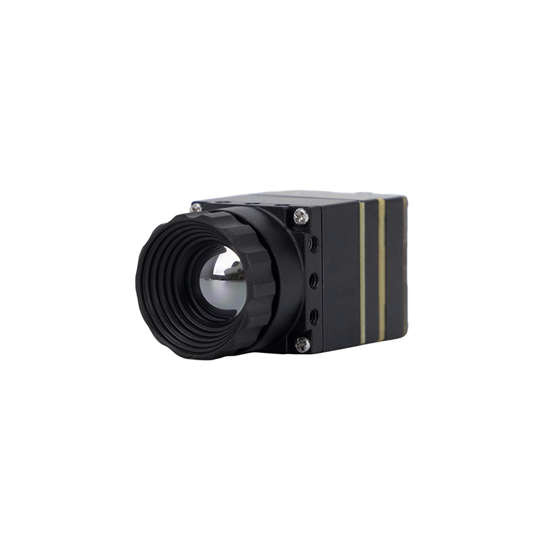
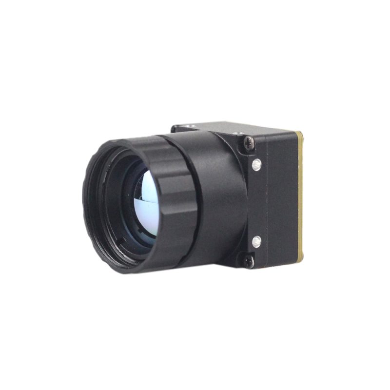
MD Series 384x288 Uncooled Infrared Thermal Camera Module
The Purpleriver MD Series thermal camera module is designed for industrial-grade precision in applications such as security surveillance, continuous temperature monitoring, and drone integration. Featuring an uncooled infrared detector with a 12μm pixel pitch, it delivers high sensitivity and sharp thermal imaging. Its compact size, plug-and-play functionality, and multiple interfaces (MIPI/USB/CVBS) ensure versatile and rapid integration into various systems. Backed by an engineering team with a Hong Kong University of Science and Technology (HKUST) background and former Huawei HiSilicon ISP expertise, this module offers full OEM/ODM customization to meet specific project requirements, ensuring exceptional performance, reliability, and adaptability.
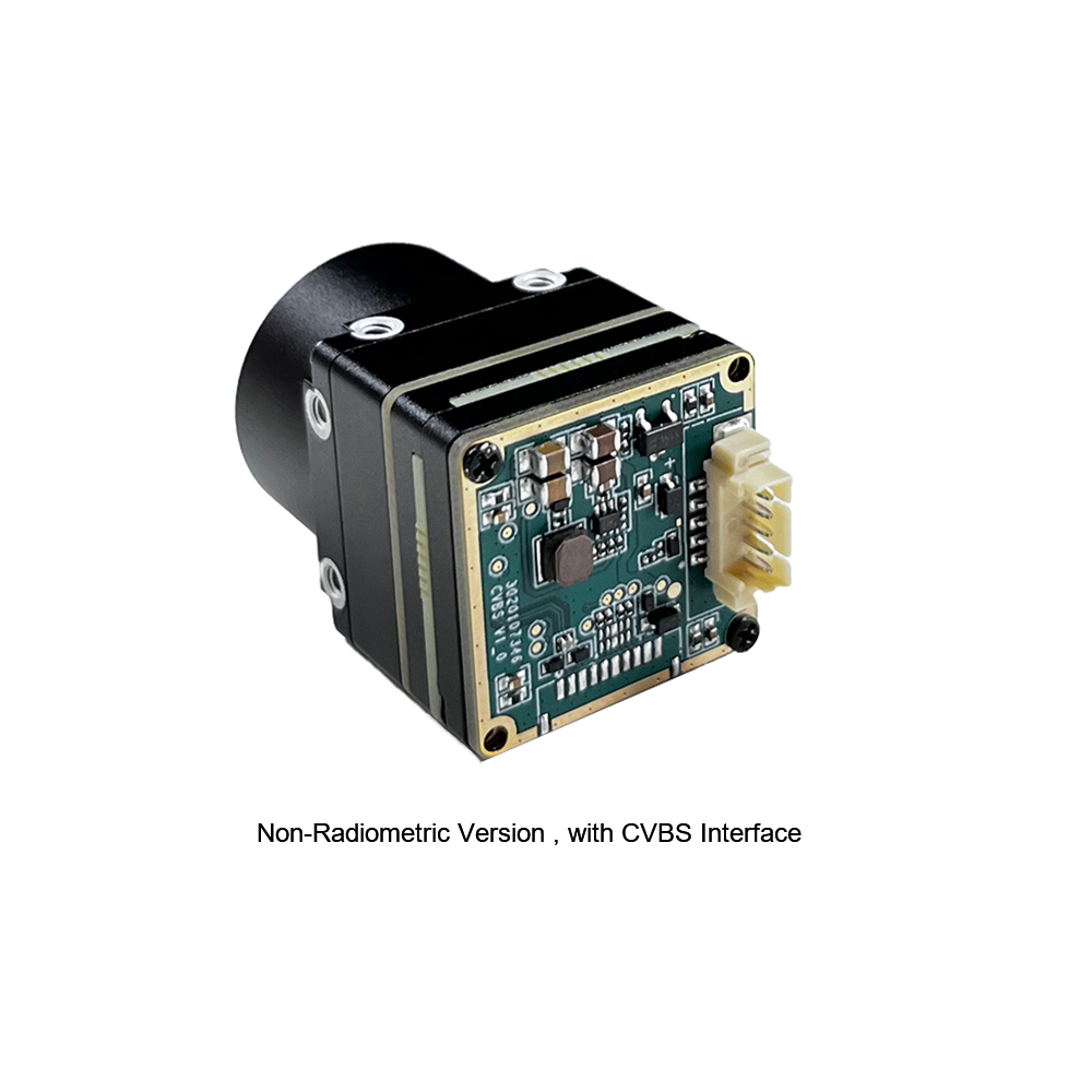
Uncooled Mini 384*288 Thermal Camera Module For Drones
The MINI series infrared thermal imaging temperature measurement module is a high-precision, small-sized, universal online radiometric thermal imager designed specifically for airborne platforms and mobile robotics. It utilizes high-quality detectors to provide stable, high-resolution performance and comprehensive radiometric functionality. Equipped with multiple hardware interfaces, it is a preferred solution across demanding application fields such as machine vision, automated safety inspection, intelligent manufacturing, power equipment maintenance, and airborne drone operations.
Comparative Technical Specifications
| Technical Parameter | MD Series 384x288 Module | Uncooled Mini 384*288 UAV Module |
|---|---|---|
| Detector Array Type | Uncooled VOx Microbolometer | Uncooled VOx Infrared Detector |
| Array Resolution | 384 × 288 Pixels (110,592 total) | 384 × 288 Pixels (110,592 total) |
| Pixel Pitch | 12 μm | 12 μm |
| Spectral Response | 8 to 14 μm (LWIR) | 8 to 14 μm (LWIR) |
| Thermal Sensitivity (NETD) | ≤ 40mK (@25°C, F/1.0) | ≤ 50mK (@25°C, F/1.0) |
| Output Interfaces | MIPI CSI-2 / USB / CVBS / UART | CVBS / USB / Serial Interface |
| Frame Rate Options | 25Hz / 30Hz / 50Hz (Export Compliant ≤9Hz available) | 25Hz / 50Hz Smooth Stream |
| Radiometric Measurement | Full-frame radiometric temperature matrix output | Universal online point, line, and area temperature analysis |
| Engineering Lineage | HKUST & Ex-Huawei HiSilicon ISP Engineering Core | Aviation-grade Drone Miniaturization Team |
| Customization Services | Full OEM/ODM Hardware, Lens & ISP Tuning | Gimbal brackets, specialized optics, custom firmware |
7. Implementation Guide: From Prototyping to Industrial Deployment
Taking an uncooled 384x288 LWIR module from bench evaluation to a rugged, field-deployable product requires a disciplined approach across electrical design, optical packaging, and edge software integration.
Step 1: Power Supply Decoupling and Low-Noise Rail Design
Microbolometer Read-Out Integrated Circuits (ROICs) measure micro-volt voltage shifts across temperature-sensitive resistor bridges. That means high-frequency switching ripple from DC-DC buck converters can bleed directly into the analog front-end, showing up as visible horizontal banding or salt-and-pepper noise across your thermal image.
- ⚙️ Use Dedicated LDOs: Power the thermal core using ultra-low-noise Low-Dropout Regulators (LDOs) with a Power Supply Rejection Ratio (PSRR) over 70dB at 100kHz.
- ⚙️ Keep Ripple Tight: Keep total voltage ripple on the core's input power rail strictly below **15mV to 30mV RMS**.
- ⚙️ Isolate Ground Returns: Keep analog sensor return paths separated from high-current inductive grounds, such as drone brushless ESCs, servo lines, and industrial motor relays.
Step 2: Radiometric Data Stream Acquisition & Temperature Conversion
When pulling raw data over MIPI CSI-2 or USB, the module sends 14-bit or 16-bit digital words representing raw infrared radiation counts ($S_{\text{raw}}$). To calculate actual physical temperatures, host software runs radiometric calibration math derived from Planck's radiation law:
T_{\text{target}} = \left( \frac{S_{\text{raw}} - \text{Offset}}{\varepsilon \cdot R \cdot \tau_{\text{atm}}} + \text{Reflected Term} \right)^{1/4} - 273.15
Here is what each parameter represents in your driver pipeline:
- ⚙️ $\varepsilon$: Target emissivity coefficient (e.g., 0.95 for matte plastic/circuit boards, 0.10 to 0.30 for shiny bare aluminum).
- ⚙️ $R$: Radiometric responsivity scale factor pulled from the module's factory flash calibration table.
- ⚙️ $\tau_{\text{atm}}$: Atmospheric transmission factor modeled from ambient humidity and target distance.
- ⚙️ $\text{Offset}$: Dynamic sensor offset updated via background non-uniformity correction cycles.
Step 3: Mechanical Mounting, Protective Windows, and IP Sealing
Standard glass and acrylic plastics are 100% opaque to long-wave infrared light (8μm to 14μm). If you need an environmentally sealed enclosure, you have to use specialized infrared optical windows:
- ⚙️ Germanium Windows: Provide high optical transmission (>90% with dual-side AR coating) and solid mechanical durability for rugged industrial enclosures.
- ⚙️ Diamond-Like Carbon (DLC) Coatings: Applied to the outer Germanium surface to withstand abrasive sand, marine salt spray, and physical impacts during drone flights.
- ⚙️ Conductive Thermal Path: Mount the core's metal housing directly against an aluminum chassis using non-silicone thermal gap pads to ensure steady heat shedding without optical outgassing.
Step 4: Edge AI Model Deployment and Inferencing
A 384x288 pixel resolution provides the ideal balance of spatial detail and lightweight data size for embedded neural networks (such as YOLOv8-thermal or MobileNet-SSD) running directly on edge NPUs (NVIDIA Jetson Orin Nano, Rockchip RK3588, etc.). Your image pipeline should normalize the incoming 14-bit radiometric frames into clean 8-bit tensors using Contrast Limited Adaptive Histogram Equalization (CLAHE) before passing data to the inference model, ensuring dependable target detection across dynamic thermal environments.
8. Frequently Asked Questions (FAQ)
Why choose a 384x288 thermal camera module over 256x192 or 640x512 alternatives?
How easily can this 384x288 thermal module integrate into lightweight drones and embedded systems?
Is a 384x288 thermal imaging module suitable for precision PCB and electronics thermal analysis?
📚 References & Further Reading
- Industry Standard: Microcontroller command, telemetry, and peripheral integration platform via Arduino
- Industry Standard: High-precision infrared optics and custom anti-reflective Germanium coatings by Rising Optics
- Related Guide: Comprehensive overview of thermal focal plane array selection in our thermal camera sensor module guide for high-res OEM cores
- Related Guide: Environmental qualification and durability methodologies in our high-temperature humidity testing guide
- Related Guide: Long-range handheld observation systems and tactical monoculars in our handheld thermal imaging hunting scope overview





