Kupno rdzenia kamery termowizyjnej: Przewodnik po wysokowydajnych modułach LWIR 640 i 384
11 września 2026
Moduł kamery termowizyjnej MIPI: Integracja LWIR o niskim opóźnieniu dla dronów i Edge AI
W inżynierii systemów wizyjnych wbudowanych integracja detekcji długofalowego promieniowania podczerwonego (LWIR) w kompaktowych, autonomicznych architekturach brzegowych stwarza istotne wyzwania na poziomie systemowym. Konwencjonalne rdzenie termowizyjne powiązane z protokołami USB 3.0 (UVC) lub Serial Peripheral Interface (SPI) często wprowadzają obciążenie CPU po stronie hosta, niemożliwe do opanowania opóźnienia buforowania jądra, niedeterministyczny jitter pakietów oraz poważne wąskie gardła przepustowości transmisji. Dla platform brzegowych o ograniczonych parametrach SWaP (rozmiar, waga, moc i koszt)—takich jak mikrobezzałogowe statki powietrzne (UAV), taktyczne mikrogimbale, autonomiczne roboty mobilne (AMR) oraz bramy wizyjne Edge AI—te wąskie gardła protokołów pogarszają wydajność widzenia komputerowego w czasie rzeczywistym, kompromitują pętle stabilizacji PID gimbala i podnoszą całkowite opóźnienie przetwarzania poza progi deterministyczne.
Standardowym rozwiązaniem architektonicznym w branży jest bezpośrednia integracja natywnego modułu kamery termowizyjnej MIPI za pośrednictwem warstwy transportowej MIPI CSI-2 (Camera Serial Interface 2). Poprzez połączenie odczytów niechłodzonych czujników mikrobolometrycznych bezpośrednio z natywnym procesorem sygnału obrazu (ISP) procesora aplikacyjnego oraz sprzętowym silnikiem bezpośredniego dostępu do pamięci (DMA), architekci systemów całkowicie omijają warstwy translacji protokołów systemu operacyjnego. Ta zmiana architektoniczna umożliwia deterministyczną, submilisekundową transmisję nieskompresowanych surowych danych radiometrycznych 14-bitowych lub 16-bitowych przy wysokich częstotliwościach klatek (30 Hz do 60 Hz) bezpośrednio do zunifikowanych przestrzeni pamięci dostępnych dla GPU i NPU, odblokowując wnioskowanie Edge AI w czasie rzeczywistym, fuzję czujników multispektralnych, śledzenie celów oraz zautomatyzowaną termografię przemysłową.
Spis treści
- 👉 Fizyka i architektura protokołu MIPI CSI-2 w obrazowaniu LWIR
- 👉 Wbudowany stos oprogramowania: Architektura sterownika V4L2, drzewo urządzeń i potoki zero-copy
- 👉 Przetwarzanie danych radiometrycznych i sprzętowa akceleracja Edge AI
- 👉 Inżynieria sprzętowa, optymalizacja SWaP-C i projektowanie elektrooptyczne
- 👉 Prezentacja techniczna przemysłowych modułów termowizyjnych MIPI i macierz specyfikacji
- 👉 Instrukcja integracji krok po kroku i rozwiązywania problemów
- 👉 Szczegółowe FAQ dotyczące integracji przemysłowej
Fizyka i architektura protokołu MIPI CSI-2 w obrazowaniu LWIR
Czujniki obrazowania termowizyjnego działają zasadniczo inaczej niż standardowe czujniki CMOS w zakresie widzialnym. Niechłodzone detektory LWIR wykorzystują matryce ogniskowe mikrobolometrów (FPA)—zazwyczaj wytwarzane z tlenku wanadu (VOx) lub krzemu amorficznego (α-Si)—czułe na promieniowanie elektromagnetyczne w atmosferycznym oknie transmisji od 8 μm do 14 μm. Każdy piksel mikrobolometru składa się z absorbera podczerwieni zawieszonego nad podłożem krzemowym za pomocą mikroskopijnych nóżek izolacji termicznej. Pod wpływem padającego promieniowania cieplnego temperatura absorbera zmienia się, powodując mierzalną zmianę jego rezystancji elektrycznej. Ta analogowa zmiana rezystancji jest digitalizowana przez zintegrowane układy odczytu (ROIC) na surowe wartości o wysokim zakresie dynamicznym, zazwyczaj 14-bitowe lub 16-bitowe liczby cyfrowe na piksel.
Przesyłanie tych surowych strumieni danych mikrobolometrycznych do wbudowanego procesora hosta wymaga interfejsu, który zachowuje integralność sygnału bez wprowadzania opóźnień obliczeniowych. Interfejs MIPI Camera Serial Interface 2 (MIPI CSI-2), w połączeniu z warstwą fizyczną (D-PHY), spełnia te wymagania dla wbudowanych systemów wizyjnych, przesyłając zserializowane dane pikseli po punkt-punkt różnicowych liniach sygnałowych regulowanych sztywnym taktowaniem sprzętowym.

Dynamika sygnalizacji warstwy fizycznej MIPI D-PHY
Elektryczna warstwa fizyczna nowoczesnego modułu termowizyjnego MIPI opiera się na specyfikacji D-PHY MIPI Alliance, asynchronicznym interfejsie synchronicznym względem źródła, wyposażonym w jedną różnicową linię zegarową oraz jedną, dwie lub cztery różnicowe linie danych. Warstwa fizyczna dynamicznie przełącza się między dwoma trybami sygnalizacji operacyjnej:
- ⚙️ Tryb High-Speed (HS): Działa z wykorzystaniem niskonapięciowej sygnalizacji różnicowej (podobnej do LVDS), z nominalnym wychyleniem różnicowym 200 mV wyśrodkowanym wokół napięcia wspólnego 200 mV (VCM). W trybie HS dane są serializowane i przesyłane z przepustowością od 80 Mb/s do 2,5 Gb/s na linię, umożliwiając wysoką zagregowaną przepustowość przy wyjątkowo niskich emisjach elektromagnetycznych promieniowanych.
- ⚙️ Tryb Low-Power (LP): Działa z wykorzystaniem jednokońcówkowej logiki sygnalizacyjnej CMOS 1,2 V. Tryb LP zarządza protokołami sterowania liniami, obsługując uzgadnianie synchronizacji ramek (takie jak Start of Transmission [SoT] i End of Transmission [EoT]), przejścia stanów niskiego poboru mocy oraz tryby uśpienia (LP-11).
W przeciwieństwie do czujników RGB 4K ze spektrum widzialnego, które wymagają przepustowości wielogigabitowej (np. 4K przy 60 kl./s zużywa cztery linie pracujące z prędkością powyżej 1,5 Gb/s na linię), niechłodzony czujnik LWIR pracujący w rozdzielczości 640 × 512 z 16-bitowym wyjściem radiometrycznym przy 50 Hz generuje zagregowany surowy ładunek danych obliczany jako:
Przepustowość = 640 × 512 × 16 bitów/piksel × 50 klatek/s ≈ 262,14 Mb/s
To wymaganie przepustowości jest wygodnie obsługiwane przez jednoliniowy (1-lane) lub dwuliniowy (2-lane) MIPI D-PHY pracujący z konserwatywną częstotliwością zegara od 400 Mb/s do 800 Mb/s na linię. Praca przy niższych częstotliwościach zegara przy jednoczesnym wykorzystaniu natywnej różnicowej sygnalizacji D-PHY minimalizuje zakłócenia elektromagnetyczne wysokiej częstotliwości (EMI) w pobliskich odbiornikach RF, co jest kluczową zaletą przy integracji czułych odbiorników komunikacyjnych i GNSS w kompaktowych platformach UAV.
Protokół pakietowania CSI-2 i radiometryczne typy danych
W warstwie protokołu CSI-2 dane obrazu są przesyłane w ustrukturyzowanych pakietach składających się z 4-bajtowego nagłówka pakietu (PH), sekwencji danych ładunku o dowolnej długości oraz 2-bajtowej stopki pakietu (PF) zawierającej 16-bitową kontrolę cykliczną nadmiarową (CRC). Nagłówek pakietu zawiera 8-bitowy bajt identyfikatora danych (DI), złożony z 2-bitowego identyfikatora kanału wirtualnego (VC) i 6-bitowego kodu typu danych (DT).
Moduły termowizyjne wykorzystują określone typy danych w strumieniu CSI-2 do przenoszenia surowych pomiarów bolometrycznych i radiometrycznych:
- ⚙️ RAW14 (typ danych 0x2D): 14-bitowe dane nieskompresowane. Mikrobolometry natywnie wytwarzają 14 bitów zakresu dynamicznego. Pakiety są formatowane przez upakowanie czterech 14-bitowych wartości pikseli w siedem kolejnych 8-bitowych bajtów, maksymalizując efektywność transmisji ładunku przez łącze fizyczne.
- ⚙️ RAW16 (typ danych 0x2E): 16-bitowe dane nieskompresowane. Każdy piksel mapuje się bezpośrednio na dwubajtową liczbę całkowitą bez znaku reprezentującą liniową odpowiedź detektora lub bezwzględne wartości temperatury radiometrycznej w centykelwinach. RAW16 upraszcza wyrównanie bajtów i adresowanie pamięci w mikroprocesorach hosta.
- ⚙️ Dane zdefiniowane przez użytkownika / osadzone 8-bitowe (typy danych 0x30 do 0x37 lub 0x12): Przemysłowe moduły termowizyjne dodają na początku lub na końcu "linię osadzoną" zawierającą metadane operacyjne: temperaturę struktury czujnika, stan wewnętrznej migawki, napięcie termistora obudowy FPA, flagi kalibracji oraz odczyty optycznego otoczenia niezbędne do obliczeń radiometrii bezwzględnej.
Porównanie architektoniczne: MIPI CSI-2 a alternatywne interfejsy wbudowane
| Standard Interfejsu | Warstwa fizyczna | Maksymalna trwała przepustowość | Opóźnienie szkło-pamięć | Obciążenie procesora hosta | Powierzchnia montażowa złącza |
|---|---|---|---|---|---|
| MIPI CSI-2 | Różnicowy D-PHY (HS/LP) | Do 2,5 Gbps na linię | < 1,5 ms (bezpośredni DMA) | < 2% (sprzętowy ISP/DMA) | Ultra-kompaktowy mikrokoncentryczny lub FPC 0,5 mm |
| USB 3.0 / UVC | Różnicowy SuperSpeed | ~3,2 Gb/s (ograniczony pakietami) | 15 do 45 ms (zmienny jitter) | 12% do 25% (odpytywanie jądra i kopie) | Bulky USB Type-C or Type-A receptacles |
| SPI (Quad/Octal) | Single-Ended Synchronous | ~50 to 100 Mbps | 40 to 120 ms (Buffer limited) | 30% to 60% (High Interrupt Load) | Standard board-to-board pin headers |
| Parallel (DVP) | 8/14-bit Single-Ended CMOS | ~600 Mbps | 3 to 8 ms | 5% to 10% | Wide 30+ pin ribbon (High EMI profile) |
Wbudowany stos oprogramowania: Architektura sterownika V4L2, drzewo urządzeń i potoki zero-copy
Direct integration of a modułu kamery termowizyjnej MIPI into modern Linux host SoCs—such as NVIDIA Jetson Orin/Xavier, Rockchip RK3588, NXP i.MX8M, or Raspberry Pi Compute Module 4/5—requires configuring the underlying kernel driver stack. Thermal cores are registered within the Linux podsystem Video4Linux2 (V4L2) framework as camera sub-devices managed through the Media Controller API.
The host system architecture follows a layered driver model: the SoC's hardware CSI-2 receiver endpoint captures incoming differential serial packets, passes them to an internal DMA channel, and transfers data into physical memory buffers. The kernel driver sets up streaming parameters via an I2C or UART control interface, ensuring synchronized exposure, framing, and on-chip thermal processing states.
The Device Tree Source (DTS) Architecture
The Linux Device Tree defines the hardware topology, linking the SoC's CSI-2 receiver endpoint to the thermal module's output port, specifying pin configurations for clock generation, reset lines, and the Camera Control Interface (typically an I2C bus operating in Fast-mode at 400 kHz).
Below is a baseline DTS node implementation for a system running a dual-lane MIPI thermal core connected to an embedded SoC:
// Device Tree Source (DTS) snippet for Industrial MIPI Thermal Module
&i2c1 {
    status = "okay";
    clock-frequency = <400000>;
    #address-cells = <1>;
    #size-cells = <0>;

    thermal_mipi: camera@38 {
        compatible = "purpleriver,mini2-mipi-thermal";
        reg = <0x38>;

        /* Hardware Reset and Power Control Lines */
        reset-gpios = <&gpio1 14 GPIO_ACTIVE_LOW>;
        powerdown-gpios = <&gpio1 15 GPIO_ACTIVE_HIGH>;
        clocks = <&cru CLK_CAM_EXT>;
        clock-names = "xvclk";
        assigned-clocks = <&cru CLK_CAM_EXT>;
        assigned-clock-rates = <24000000>;

        /* V4L2 Media Bus Port Definition */
        port {
            thermal_to_csi: endpoint {
                remote-endpoint = <&csi_in_thermal>;
                data-lanes = <1 2>;
                clock-lanes = <0>;
                clock-noncontinuous;
                link-frequencies = /bits/ 64 <200000000 400000000>;
            };
        };
    };
};

&csi2_host {
    status = "okay";
    ports {
        #address-cells = <1>;
        #size-cells = <0>;
        port@0 {
            reg = <0>;
            csi_in_thermal: endpoint {
                remote-endpoint = <&thermal_to_csi>;
                data-lanes = <1 2>;
            };
        };
    };
};
For embedded system developers working through hybrid visual-thermal builds, evaluating specialized hardware integration workflows is critical. Learn more about sensor topology alignments and dual-band configurations in our CMOS sensor thermal camera module integration guide.
V4L2 Sub-Device Driver Core Implementation
The kernel driver implements standard V4L2 sub-device operations structures: v4l2_subdev_core_ops, v4l2_subdev_video_ops, oraz v4l2_subdev_pad_ops. When user-space applications initiate video capture via the VIDIOC_STREAMON ioctl, the driver configures the internal FPGA or ASIC of the thermal core over I2C, places the microbolometer sensor into continuous readout mode, and primes the host-side CSI-2 receiver.
static const struct v4l2_subdev_video_ops thermal_video_ops = {
    .s_stream = purpleriver_thermal_s_stream,
    .g_frame_interval = purpleriver_thermal_g_frame_interval,
    .s_frame_interval = purpleriver_thermal_s_frame_interval,
};

static const struct v4l2_subdev_pad_ops thermal_pad_ops = {
    .enum_mbus_code = purpleriver_thermal_enum_mbus_code,
    .get_fmt        = purpleriver_thermal_get_fmt,
    .set_fmt        = purpleriver_thermal_set_fmt,
};

static int purpleriver_thermal_s_stream(struct v4l2_subdev *sd, int enable)
{
    struct purpleriver_dev *sensor = to_purpleriver_dev(sd);
    int ret = 0;

    mutex_lock(&sensor->lock);
    if (enable) {
        /* Initialize core registers: Set 14-bit radiometric readout, enable streaming */
        ret = purpleriver_write_reg(sensor->client, REG_SENSOR_MODE, MODE_STREAMING_RAW14);
        if (ret < 0) goto exit;
        ret = purpleriver_write_reg(sensor->client, REG_STREAM_ENABLE, 0x01);
    } else {
        ret = purpleriver_write_reg(sensor->client, REG_STREAM_ENABLE, 0x00);
    }
exit:
    mutex_unlock(&sensor->lock);
    return ret;
}
Zero-Copy Memory Management via DMABUF Architecture
High-throughput radiometric image processing cannot afford CPU-driven memory copies (memcpy) across user-kernel boundaries. Transferring 640 × 512 16-bit frames at 50 Hz using conventional read operations introduces memory bus saturation and increases frame delivery latency by 15 ms to 30 ms.
To achieve sub-millisecond transfer latencies, modern edge pipelines utilize DMABUF memory sharing:
- ⚙️ Buffer Allocation: Contiguous memory blocks are pre-allocated in system RAM via the Linux Contiguous Memory Allocator (CMA) or hardware buffer allocators (such as NVIDIA
NvBufSurfaceor Rockchip MPP/RGA memory pools). - ⚙️ Descriptor Export: These allocated buffers are exported to user-space applications as native Linux file descriptors (DMABUF FDs).
- ⚙️ Hardware DMA Streaming: The host SoC's MIPI CSI-2 hardware interface transfers incoming packet payloads directly into these physical memory addresses without host CPU intervention.
- ✅ Direct NPU/GPU Ingestion: Edge AI inference engines (such as TensorRT, DeepStream, or ONNX Runtime) bind directly to these shared memory pointers. Zero-copy access eliminates memory copying overhead and achieves glass-to-inference execution latencies below 1.5 milliseconds.
Przetwarzanie danych radiometrycznych i sprzętowa akceleracja Edge AI
Unlike visible-spectrum image sensors that output ready-to-display sRGB color spaces, uncooled LWIR sensors capture raw thermal flux emitted across the scene. The digitized output corresponds to detector resistance rather than human visual perceptions. Developing real-time vision pipelines requires applying specialized calibrations and transformations to extract accurate temperature information.
Non-Uniformity Correction (NUC) and Bad Pixel Replacement (BPR)
Microbolometer focal plane arrays exhibit pixel-to-pixel variations in responsivity and dark offset voltage due to semiconductor fabrication tolerances. The response of an individual pixel i is represented mathematically by the linear model:
Vi(T) = Gi × Φ(T) + Oi
Gdzie:
- ⚙️ Gi: Individual pixel responsivity (gain) coefficient.
- ⚙️ Φ(T): Incident infrared irradiance originating from target scene temperature T.
- ⚙️ Oi: Individual spatial offset, heavily influenced by the focal plane array's internal substrate temperature.
To eliminate fixed-pattern noise (FPN) and achieve thermal sensitivities below 40 mK, the thermal processing engine performs three distinct operations:
- ⚙️ Two-Point Gain Calibration: Calibrates individual pixel gain coefficients (Gi) using uniform blackbody calibration sources across two known reference temperatures (T1 and T2). These coefficients are stored in non-volatile sensor memory.
- ⚙️ Offset Compensation (Shutter Calibration): An electromechanical shutter periodically moves into the optical path for 100 to 300 ms, exposing the array to a uniform thermal reference. The module recalculates offset tables (Oi) to compensate for ambient thermal drift. High-end cores deploy shutterless algorithms that continuously update offset matrices using real-time temperature readings from internal housing and lens thermistors.
- ⚙️ Zastępowanie uszkodzonych pikseli (BPR): Dead, unresponsive, or noisy pixels that fall outside three standard deviations of the array's median Gaussian distribution are flagged during factory calibration. In operation, hardware pipelines replace these values in real time using 3×3 median or bilinear interpolation from surrounding functional pixels.
Conversion from Raw Digital Values to Absolute Temperature
Following Non-Uniformity Correction, the module produces a 14-bit or 16-bit linear digital output (Digital Numbers, or DN). Converting these values into absolute radiometric temperature units (Kelvin or Celsius) requires calculating the inverted Planck radiation function:
Tcel = B / ln( R1 / (R2 × (DN - Odrift)) + F )
Gdzie R1, R2, B, oraz F represent empirical calibration constants established via laboratory blackbody profiling, and Odrift accounts for real-time substrate temperature variations. In industrial radiometric modules, this calculation is executed either on the internal module processor or mapped into optimized vector execution units (such as ARM NEON or NVIDIA CUDA kernels) on the host processor.
High-Contrast Dynamic Range Compression for Neural Networks
Contemporary Edge AI object detection models (such as YOLOv8, YOLOv10, or RT-DETR) are architected for 3-channel 8-bit input tensors (values ranging from 0 to 255). Linearly downscaling an uncompressed 14-bit radiometric dynamic range (0 to 16,383) to 8-bit discards fine thermal gradients, often obscuring faint targets (such as humans or distant vehicles) against warm backgrounds.
To preserve target details, the software pipeline splits the incoming MIPI CSI-2 stream into dual processing branches:
- ⚙️ The Radiometric Analytic Stream: Preserves the raw 14-bit or 16-bit linear radiometric depth. This pipeline feeds threshold algorithms, spot temperature queries, and automated fire or overheating alarm routines.
- ⚙️ The Vision AI Inference Stream: Passes raw data through a cyfrowe wzmocnienie szczegółów (DDE) filter and Contrast Limited Adaptive Histogram Equalization (CLAHE). These algorithms separate the scene into a low-frequency base layer (representing overall background temperature gradients) and a high-frequency detail layer (highlighting sharp boundaries, edges, and signatures). The layers are dynamically balanced into an 8-bit contrast-enhanced representation, maximizing edge feature extraction for neural network inference.
For additional details on deploying deep learning models over localized radiometric stream architectures, review our technical guide on промышленные мини-модули LWIR с ИИ (industrial mini-LWIR modules with AI).
Inżynieria sprzętowa, optymalizacja SWaP-C i projektowanie elektrooptyczne
Deploying thermal vision payloads into airborne micro-gimbals, handheld inspection equipment, and small mobile robots demands strict attention to Size, Weight, Power, and Cost (SWaP-C) budgets alongside high-speed printed circuit board (PCB) design standards.
High-Speed PCB Layout & Signal Integrity Guidelines
The MIPI D-PHY physical layer operates with rapid signal rise and fall times (tr, tf < 200 ps). High-speed layout oversights can cause transmission line reflections, differential impedance mismatches, and severe packet corruption:
- ⚙️ Differential Impedance Control: All differential clock and data trace pairs must be routed to maintain a tightly controlled 100 Ω ± 10% differential impedance (50 Ω single-ended reference).
- ⚙️ Intra-Pair Skew Matching: Trace length differences between positive (P) and negative (N) conductors within a differential pair must not exceed 0.15 mm (< 1 ps phase skew). Excessive intra-pair skew degrades common-mode rejection and increases electromagnetic emissions.
- ⚙️ Inter-Pair Skew Matching: Length mismatches between the clock lane pair and any corresponding data lane pair must remain below 0.5 mm to ensure timing margins are preserved across the high-speed receiver.
- ⚙️ Continuous Reference Plane: MIPI traces must be routed across unbroken, continuous ground reference planes. Traces must not cross splits, power planes, or voids, which create impedance discontinuities and generate common-mode noise.
- ⚙️ Interconnect Selection: Gimbal payloads require specialized low-profile micro-coaxial ribbons or shielded flexible printed circuits (FPC). High-reliability connectors from precision manufacturers like Amphenol maintain signal integrity across moving gimbal pivots and slip rings without introducing mechanical binding.
Optical Materials Engineering: Germanium vs. Chalcogenide Glass
Because optical glass is opaque in the 8 μm to 14 μm infrared band, uncooled LWIR lenses require specialized optical substrates:
- ⚙️ Monokrystaliczny German (Ge): Germanium exhibits a high refractive index (n ≈ 4.00 at 10 μm), enabling compact, low-aberration multi-element optical assemblies. However, Germanium features a high temperature-dependent refractive index coefficient (dn/dt = 3.96 × 10⁻⁴/°C) and exhibits optical absorption runaway above +100°C. It is also dense and represents a significant material cost.
- ✅ Szkło chalkogenidkowe: Engineered chalcogenide glasses—such as those produced by LightPath Technologies—offer lower mass, reduced material costs, and significantly lower dn/dt values. These characteristics enable passive athermalization across wide temperature ranges (-40°C to +85°C) without motorized focus mechanics, reducing gimbal payload mass.
Engineers designing defense or long-range intelligence, surveillance, and reconnaissance (ISR) payloads can contrast these lightweight short-to-medium-range micro-optics against larger systems in our breakdown of the 1280x1024 12μm long range thermal imaging sight scope.
Prezentacja techniczna przemysłowych modułów termowizyjnych MIPI i macierz specyfikacji
Below is a detailed examination of two industrial-grade MIPI thermal camera modules optimized for unmanned payloads, tactical micro-gimbals, and embedded edge computing architectures.
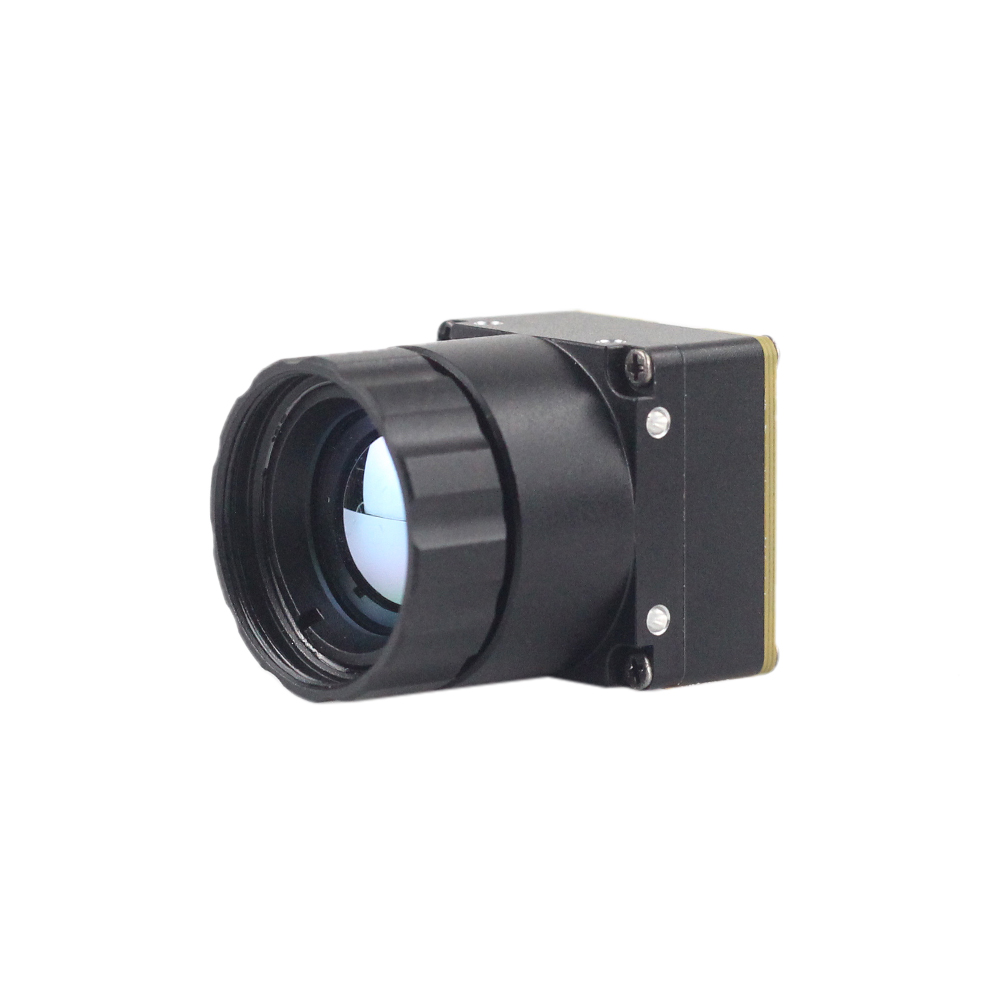
Purpleriver Mini2 640x512 9mm Uncooled MIPI Thermal Imaging Module
to cud inżynierii zaprojektowany specjalnie do środowisk o ograniczonych parametrach SWaP. Dzięki miniaturyzacji elektroniki bez poświęcania jakości sensora dostarczamy rdzeń, który mieści się w najciaśniejszych przestrzeniach. Mini2 640x512 9mm is an uncooled LWIR camera module designed for airborne drone payloads, tactical gimbals, and real-time robotic vision systems. Delivering sharp and crisp image presentation, compact form factor, and low unit cost, this module integrates an uncooled VOx detector with a 12 μm pixel pitch and an athermalized 9mm lens. It supports native MIPI CSI-2 digital output for direct integration into embedded host processors, bypassing intermediate interface bridges.
- ⚙️ Rozdzielczość: 640 × 512 Active Pixels (VGA Thermal)
- ⚙️ Rozstaw pikseli: Mikrobolometr z tlenku wanadu (VOx) 12 μm
- ✅ Czułość termiczna: ≤ 40 mK (NETD at f/1.0, 300K)
- ⚙️ Video Output: 2-lane MIPI CSI-2, DVP, or USB options
- ✅ Pobór mocy: < 900 mW (Steady State)
Purpleriver Mini 256x192 Uncooled LWIR Thermal Camera Module
to cud inżynierii zaprojektowany specjalnie do środowisk o ograniczonych parametrach SWaP. Dzięki miniaturyzacji elektroniki bez poświęcania jakości sensora dostarczamy rdzeń, który mieści się w najciaśniejszych przestrzeniach. Miniaturowy niechłodzony moduł kamery termowizyjnej LWIR 256 adopts high-performance infrared detectors designed for clear thermal imaging and accurate temperature measurement. Engineered to capture infrared radiation and output uniform thermal imagery with integrated radiometry, its ultra-lightweight profile suits weight-critical deployments, including mine detection drones, search and rescue robots, and micro-UAV swarms.
- ⚙️ Rozdzielczość: 256 × 192 Active Pixels
- ⚙️ Rozstaw pikseli: 12 μm High-Sensitivity Uncooled Microbolometer
- ✅ Czułość termiczna: ≤ 50 mK (NETD at f/1.0)
- ⚙️ Radiometria precyzyjna: Point, line, and area temperature tracking with accurate output
- ✅ Weight Profile: ≤ 12 g total mass (SWaP-optimized)
Comprehensive Specification Matrix
| Parametr specyfikacji | Purpleriver Mini2 640x512 9mm | Purpleriver Mini 256x192 Core |
|---|---|---|
| Architektura detektora | Niechłodzona matryca FPA z mikrobolometrem VOx | Uncooled LWIR Microbolometer FPA |
| Rozdzielczość matrycy | 640 × 512 pikseli | 256 × 192 pikseli |
| Rozstaw pikseli | 12 μm | 12 μm |
| Czułość spektralna | Przegląd modułów kamer termowizyjnych w języku rosyjskim | Przegląd modułów kamer termowizyjnych w języku rosyjskim |
| Czułość NETD | ≤ 40 mK (f/1.0 at 300K) | ≤ 50 mK (f/1.0 at 300K) |
| Frame Output Rates | 25 Hz / 30 Hz / 50 Hz | 25 Hz / 30 Hz |
| Interfejsy cyfrowe | MIPI CSI-2 (2-lane) / DVP / USB | MIPI CSI-2 (1 or 2-lane) / SPI |
| Control Command Bus | I2C / UART (Up to 921,600 bps) | I2C / UART |
| Radiometric Range | -20°C to +150°C (High Gain); up to +550°C (Low Gain) | -20°C to +150°C (Industrial Radiometry) |
| Measurement Accuracy | ±2°C or ±2% of reading | ±2°C or ±2% of reading |
| Standard Optic | 9mm (HFOV ≈ 48°) Athermalized | Integrated Wide-Angle Micro-Lens |
| Operational Power | < 900 mW (Continuous operation) | < 450 mW (Ultra-low power) |
| Module Mass | ≈ 18 g (Core) / 28 g (With 9mm Lens) | ≤ 12 g Total |
Instrukcja integracji krok po kroku i rozwiązywania problemów
Executing a reliable integration of a MIPI thermal camera module into an embedded carrier board requires following a structured hardware and software validation methodology.
Step 1: Hardware Rail Verification
Prior to powering the module, verify all voltage supply rails using an oscilloscope. Uncooled microbolometers are sensitive to power supply noise. Ensure the analog supply rail (VDD_ANA) exhibits less than 10 mVRMS ripple. High power ripple directly degrades the sensor's Noise Equivalent Temperature Difference (NETD), introducing horizontal banding across the raw image stream.
Step 2: Device Tree Compilation and Kernel Registration
Compile the Device Tree source overlay and load the driver kernel module into the Linux kernel space. Verify that the thermal sub-device acknowledges I2C commands using standard Linux utilities:
# Verify module acknowledges on I2C bus 1 at address 0x38
i2cdetect -y -r 1

# Inspect the kernel ring buffer for successful sub-device probing
dmesg | grep -i purpleriver
# Expected Output:
# [    4.120349] purpleriver_thermal 1-0038: Sensor probed successfully. Model: Mini2-640
# [    4.121110] purpleriver_thermal 1-0038: Subdev registered as /dev/v4l-subdev2
Step 3: Stream Capture Verification with V4L2 Utilities
Query the host video device node using v4l2-ctl to confirm supported pixel formats and negotiate the streaming format before launching higher-level vision applications:
# Query available pixel formats on host video node
v4l2-ctl --device=/dev/video0 --list-formats-ext

# Capture 100 test frames directly to file using direct MMAP DMA
v4l2-ctl --device=/dev/video0 \
         --set-fmt-video=width=640,height=512,pixelformat='Y16 ' \
         --stream-mmap --stream-count=100 \
         --stream-to=test_stream.raw
Step 4: Hardware-Accelerated GStreamer Pipeline Integration
To feed raw radiometric frames directly into hardware-accelerated processing pipelines, configure a zero-copy GStreamer pipeline. The pipeline below splits the incoming 16-bit raw data, directing one stream to hardware color-mapping for operator display and the other directly to an appsink for neural network inference:
gst-launch-1.0 v4l2src device=/dev/video0 ! \
    video/x-raw, format=GRAY16_LE, width=640, height=512, framerate=30/1 ! \
    tee name=thermal_tee \
    thermal_tee. ! queue leaky=1 ! \
        nvvideoconvert ! \
        video/x-raw(memory:NVMM), format=RGBA ! \
        nvdsosd ! nveglglessink sync=false \
    thermal_tee. ! queue leaky=1 ! \
        appsink name=radiometric_sink emit-signals=true max-buffers=1 drop=true
Diagnostic Matrix: Common Integration Pitfalls
| Reported Fault | Root Cause Analysis | Engineering Resolution |
|---|---|---|
| "MIPI CSI-2 FIFO Overflow / Packet CRC Error" | Differential length mismatch or clock-lane skew exceeding physical receiver margins. | Check trace routing; enforce intra-pair skew < 0.15mm. Ensure continuous ground plane under high-speed traces. |
| Driver fails to initialize: "LP-11 State Timeout" | Host receiver timed out waiting for module D-PHY to enter Low-Power standby state before High-Speed transmission. | Add a hardware reset hold time (trst > 15 ms) in DTS. Match clock mode (continuous vs. non-continuous) with module settings. |
| Frame displays severe fixed pattern noise (FPN) | Internal microbolometer temperature shifted during continuous operation without offset recalibration. | Trigger an internal shutter calibration via I2C command, or enable continuous shutterless compensation in the module's driver controls. |
Film demonstracyjny miniaturowego rdzenia termowizyjnego 640×512
Szczegółowe FAQ dotyczące integracji przemysłowej
Why choose a MIPI CSI-2 thermal camera module over USB or SPI interfaces for embedded vision?
SPI interfaces present bandwidth constraints. Standard single or quad SPI buses max out between 50 Mbps and 100 Mbps, making them incapable of transporting an uncompressed 640 × 512 14-bit stream at 30 Hz to 50 Hz without aggressive down-sampling or frame drops. In contrast, MIPI CSI-2 interfaces directly with the host processor's camera subsystem. Uncompressed raw radiometric data is delivered via hardware Direct Memory Access (DMA) into unified memory buffers with less than 2% CPU overhead and under 1.5 ms of glass-to-memory latency. This deterministic transfer is essential for mission-critical Edge AI target tracking and multi-sensor fusion.
How complex is embedded Linux driver bring-up for Purpleriver MIPI thermal modules?
The kernel driver registers as a standard v4l2_subdev, exposing interfaces for format configuration, framerate negotiation, and thermal parameter control via standard or extended V4L2 controls. Once the driver binds to the sensor, user-space utilities like media-ctl link the camera pad to the host SoC's capture interface. Reference Board Support Packages (BSPs), Device Tree source overlays, and pre-compiled GStreamer pipelines are available for platforms including NVIDIA Jetson (JetPack 5.x/6.x), Rockchip RK3588, and Raspberry Pi CM4. These resources help engineering teams complete driver integration in a few working days rather than months.
Are these MIPI thermal modules suitable for weight-sensitive drone and gimbal applications?
Operating power consumption is maintained below 900 mW for the Mini2 and under 450 mW for the Mini 256. This low power draw extends flight endurance and minimizes internal heat buildup. In sealed IP67 payloads, excess internal heat can cause microbolometer temperature drift and force repeated shutter recalibrations; these modules' low power dissipation helps preserve thermal stability. Additionally, their fine-pitch flexible printed circuit (FPC) connections can route cleanly through compact mechanical gimbal joints and slip rings without introducing mechanical drag on stabilization motors.
📚 Piśmiennictwo i dalsze lektury
- ⚙️ Standard branżowy: High-speed interconnect and micro-coaxial cable assemblies for aerospace and robotic vision: Amphenol Corporation
- ⚙️ Standard branżowy: Molded chalcogenide infrared optical engineering and passive athermalization: LightPath Technologies
- ⚙️ Powiązany przewodnik: Multi-sensor design and dual-band optical alignment: CMOS Sensor Thermal Camera Module Integration Guide
- ⚙️ Powiązany przewodnik: Advanced neural network deployment over localized infrared arrays: Промышленные мини-модули LWIR с ИИ (Industrial Mini LWIR Modules with AI)
- ⚙️ Powiązany przewodnik: High-definition tactical electro-optics: 1280x1024 12μm Long Range Thermal Imaging Sight Scope