Best Thermal Module Solutions: High-Performance LWIR Camera Cores for OEM Integration
2026年10月12日
How to Choose the Best Infrared Camera Module: OEM Integration Guide for Drones & Embedded AI
2026年10月13日
Best LWIR Camera Module for Embedded & UAV Systems: 2024 OEM Integration Guide
In autonomous unmanned aerial vehicle (UAV) navigation, tactical aerial reconnaissance, critical infrastructure inspection, and automated search-and-rescue (SAR) missions, optical perception payloads continually encounter zero-lux environments, dense atmospheric obscurants, optical particulate scattering, particulate-heavy smoke, and intense solar glare. Under these unforgiving field conditions, visible-spectrum complementary metal-oxide-semiconductor (CMOS) and active near-infrared (NIR) sensors experience absolute failure modes, losing situational awareness entirely due to an absence of reflected ambient illumination. Integrating an uncooled LWIR camera module (Long-Wave Infrared, operating deterministically within the 8 μm to 14 μm spectral transmission window) provides an uncompromising engineering solution by acquiring passive long-wave thermal radiation directly from objects rather than relying on reflected ambient photons. By detecting microscopic temperature differentials through passive thermal blackbody emissions, microbolometer-based LWIR payloads unlock mission-critical capabilities ranging from sub-surface landmine localization to autonomous night-time obstacle avoidance.
However, selecting, packaging, and driving an embedded LWIR payload into a micro-unmanned aerial vehicle, robotic gimbal assembly, or edge-AI companion computer demands a rigorous balance of competing mechanical, thermal, electrical, and optical design criteria. Optical systems engineers and embedded firmware developers must carefully navigate strict Size, Weight, Power, and Cost (SWaP-C) constraints while resolving integration challenges: preserving 14-bit digital radiometric precision across fluctuating dynamic operational ranges, managing continuous non-uniformity correction (NUC) mechanical shutter events without dropping critical frames during high-speed tracking maneuvers, mitigating thermal drift induced by adjacent brushless gimbal motor dissipation, and routing multi-channel thermal raw data across bandwidth-restricted embedded interfaces. This engineering integration guide delivers an exhaustive technical breakdown of uncooled LWIR sensor cores, detailing core detector physics, interface protocols, optical configurations, edge-AI image processing pipelines, and a comparative evaluation of the industry's leading ultra-compact OEM thermal imaging cores.
Table of Contents
- 👉 1. What is an LWIR Camera Module? Physics, Detectors, and Spectral Selection
- 👉 2. SWaP-C Engineering Constraints in UAV & Micro-Robotic Payloads
- 👉 3. Radiometric Measurement vs. Visual Inspection Payloads
- 👉 4. Embedded Hardware Interfaces: MIPI-CSI, USB, DVP, and LVDS
- 👉 5. Optical Design & Thermal Lens Selection: Germanium vs. Chalcogenide
- 👉 6. OEM Product Benchmark: Mini 256 vs. Mini 640 LWIR Camera Modules
- 👉 7. Non-Uniformity Correction (NUC), Bad Pixel Replacement, and Shutter Management
- 👉 8. Edge AI Computer Vision Integration for Thermal Streams
- 👉 9. Frequently Asked Questions (FAQ)
1. What is an LWIR Camera Module? Physics, Detectors, and Spectral Selection
An uncooled LWIR camera module is an integrated electro-optical subsystem designed to capture long-wavelength infrared electromagnetic radiation (nominally 8 μm to 14 μm) and convert incident photon flux into spatial temperature arrays or calibrated digital video outputs. Unlike conventional visible-spectrum image sensors that leverage the photoelectric effect within crystalline silicon across visible (0.4–0.7 μm) or near-infrared (NIR, 0.75–1.1 μm) bands, an LWIR microbolometer functions through thermal absorption principles. Incident long-wave radiation heats an array of thermally isolated micro-absorber bridges suspended above a silicon substrate, inducing a measurable shift in the electrical resistance of the underlying material. For a comprehensive review of the physical principles governing thermal radiation and emissive heat transfer, consult the foundational treatise on Wikipedia Thermal Imaging.
The core of the uncooled long-wave infrared core consists of an array of micro-machined pixels forming a Focal Plane Array (FPA). Each individual pixel microbridge features a structural absorber layer tuned precisely to absorb infrared energy within the 8 to 14 micrometer atmospheric window. The absorber transfers the absorbed heat to an underlying thermistor film layer. Because these bridges are mechanically suspended by thin, high-aspect-ratio lithographic legs within an evacuated micro-cavity under extreme high vacuum (often below 10 millitorr), thermal loss through atmospheric conduction is effectively eliminated. This isolates radiative thermal exchange as the primary thermal transport mechanism, allowing minute fluctuations in radiant scene flux to produce measurable electronic shifts within the Readout Integrated Circuit (ROIC).
1.1 Atmospheric Transmission Windows: Why 8–14 μm Dominates Embedded Applications
Atmospheric molecular absorption dictates infrared system efficacy across long standoff distances. Atmospheric gases, including water vapor, carbon dioxide, nitrous oxide, and ozone, produce strong vibrational and rotational absorption bands that attenuate infrared electromagnetic wavelengths. This atmospheric filtering leaves three discrete operational transmission windows across the infrared spectrum:
- ⚙️ Short-Wave Infrared (SWIR, 1.4–3 μm): This band behaves similarly to visible spectrum light, relying predominantly on reflected photons rather than direct self-emission from terrestrial ambient objects. While exceptional for penetrating haze, low-moisture maritime fog, and specialized industrial spectroscopy, SWIR provides virtually zero passive thermal signature capability when evaluating objects at standard ambient temperatures (300 Kelvin).
- ⚙️ Mid-Wave Infrared (MWIR, 3–5 μm): Characterized by high thermal contrast, MWIR excels in extremely hot target identification, high-speed missile tracking, and long-range coastal surveillance over humid atmospheric paths. However, physics dictates that MWIR detector architectures demand active cryogenic cooling to approximately 77 Kelvin (-196°C) to suppress sensor dark current and prevent self-radiation blinding. Stirling-cycle cryocoolers introduce unacceptable mass penalties (often exceeding 1 to 2 kg), high electrical power demands (15 to 40 watts continuous), limited mechanical operational lifespans (typically 3,000 to 8,000 hours MTBF), and prohibitive five-figure component costs.
- ⚙️ Long-Wave Infrared (LWIR, 8–14 μm): Under Planck’s Radiation Law and Wien’s Displacement Law, terrestrial blackbody radiators operating at ambient temperatures (roughly 300 Kelvin or 27°C) exhibit peak radiant spectral exitance directly centered between 9.5 μm and 10 μm. The 8 to 14 μm LWIR band perfectly encompasses this ambient terrestrial emission peak. Consequently, uncooled microbolometers operating across the LWIR spectral spectrum do not require cryogenic cooling systems. The resulting systems achieve up to a 90% reduction in physical volume, mass, and power consumption, establishing the uncooled LWIR camera module as the undisputed standard for robotic and micro-UAV deployments.
1.2 Uncooled VOx (Vanadium Oxide) vs. a-Si (Amorphous Silicon) Microbolometers
When engineering an embedded infrared vision payload, selecting the core material composition of the microbolometer thin-film membrane directly defines operational dynamic range, signal-to-noise ratio (SNR), and Noise Equivalent Temperature Difference (NETD). The two predominant commercial and industrial thin-film technologies are Vanadium Oxide (VOx) and Amorphous Silicon (a-Si):
Vanadium Oxide (VOx): Vanadium Oxide is a transitional metal oxide exhibiting a high Temperature Coefficient of Resistance (TCR), typically ranging from -2%/K to -3%/K at ambient operational temperatures. This high TCR translates to exceptional thermal responsivity: small shifts in incident thermal radiation yield pronounced variations in electrical resistance. Furthermore, VOx demonstrates markedly low 1/f flicker noise and low Johnson noise characteristics when compared to alternative thin-film semiconductors. Consequently, high-grade VOx detectors routinely achieve system-level thermal sensitivity ratings below 35 to 40 mK at f/1.0. Suspended via micro-electro-mechanical systems (MEMS) surface machining on thin silicon nitride bridges within a hermetically sealed vacuum package, VOx bolometers feature rapid thermal time constants (typically 8 to 12 ms), enabling rapid 50 Hz/60 Hz frame acquisition without residual visual smear during dynamic drone maneuvers.
Amorphous Silicon (a-Si): Amorphous Silicon offers simplified semiconductor manufacturing advantages because it can be deposited directly within standard silicon CMOS fabrication foundries, yielding cost efficiencies during high-volume production. However, a-Si exhibits a lower TCR (roughly -1.5%/K to -2.0%/K) coupled with significantly higher internal structural disorder, which introduces elevated 1/f noise floors. As a direct engineering consequence, an uncooled a-Si LWIR camera module typically yields an inferior thermal sensitivity metric, hovering between 50 mK and 70 mK NETD under equivalent optical configurations. Furthermore, a-Si arrays exhibit higher thermal mass and slower thermal response constants, which manifest as noticeable pixel latency and visual ghosting when mounted on high-speed aerial platforms tracking rapid ground motions.
For high-reliability autonomous robotics, tactical UAV operations, military mine localization, and precision radiometric analysis, VOx remains the industry-standard choice. Its superior signal-to-noise ratio, ultra-fast thermal response time, and sub-40 mK thermal sensitivity ensure the capture of microscopic thermal contrasts under harsh ambient conditions.
2. SWaP-C Engineering Constraints in UAV & Micro-Robotic Payloads
The proliferation of unmanned aerial multi-rotors, fixed-wing vertical takeoff and landing (VTOL) systems, and tactical ground rovers has transformed embedded sensor design into an exercise in aggressive SWaP-C optimization (Size, Weight, Power, and Cost). In aerial robotics, every physical millimeter and fractional milliampere allocated to the sensor payload directly degrades operational flight envelope performance.
2.1 Mass Budgets, Gimbals, and Center-of-Gravity Dynamics
Within rotorcraft and multi-rotor flight dynamics, flight endurance is governed by the structural mass fraction: the ratio of payload weight to total battery capacity and aerodynamic lift. Mathematically, the reduction in hover endurance relative to added payload mass is characterized by the proportional mass equation:
Δt_flight ≈ - (Δm / m_total) × t_hover
Integrating an legacy thermal camera payload weighing upwards of 150 to 200 grams demands larger airframe structural members, high-torque brushless gimbal motors, and elevated battery discharge rates, typically diminishing multi-rotor mission endurance by 4 to 8 minutes. Conversely, migrating to an ultra-miniaturized, uncooled LWIR camera module featuring a strict 21 mm × 21 mm mechanical outline and an integrated bare mass below 20 to 25 grams radically shifts the payload engineering dynamic:
- ✅ Inertial Mass and Gimbal Stabilization: Gimbal stabilization systems depend upon stabilizing an optical payload across pitch, roll, and yaw axes using brushless direct-drive motors. The rotational moment of inertia (I = m × r²) scales quadratically with sensor distance from the pivot axis and linearly with total payload mass. A sub-30 g thermal core with a compact center of gravity minimizes motor torque demands. This permits the structural integration of ultra-lightweight gimbal motors (such as 1206 to 1605 brushless stators), drastically reducing mechanical stabilization power consumption while eliminating high-frequency angular jitter during turbulent atmospheric wind corrections.
- ✅ Airframe Aerodynamics: The minimal 21 mm profile permits structural encapsulation directly inside aerodynamically contoured UAV noses, wings, or internal payload bays, preserving laminar airflow and mitigating parasite drag on fixed-wing VTOL aircraft.
2.2 Electrical Power Budgets: Quiescent Draw, Shutter Spikes, and Thermal Dissipation
Embedded robotic platforms maintain strictly regulated auxiliary power buses, standardizing on direct 3.3 V, 5.0 V, or 12.0 V buck-regulated distribution networks. An embedded uncooled LWIR camera module introduces complex electrical loading profiles that must be anticipated during power delivery network (PDN) design:
- ⚙️ Quiescent Steady-State Consumption: During continuous pixel acquisition and digital transmission over MIPI CSI-2 or parallel interfaces, modern high-efficiency VOx thermal modules draw remarkably low electrical power, operating consistently within the 0.8 W to 1.5 W domain. This modest quiescent draw prevents thermal drain on auxiliary lithium-polymer (LiPo) power rails, preserving battery reserves for power-hungry edge-AI acceleration compute modules, such as the NVIDIA Jetson Orin Nano or Orin NX architectures which draw between 7 W and 25 W under continuous neural inference.
- ⚙️ Transient Inductive Shutter Current Inrush: Embedded developers must design power delivery stages to absorb sudden inductive current spikes during Non-Uniformity Correction (NUC) shutter events. Microbolometers utilize a miniature electromagnetic mechanical solenoid that drops an internal optical paddle across the focal plane for roughly 100 to 250 milliseconds. Driving this solenoid can cause momentary peak current draws jumping from a nominal steady-state of 180–220 mA up to 600–800 mA at 5 V. Without adequate local low-ESR ceramic decoupling capacitors and correctly sized inductor chokes on the power regulation rail, this transient load step induces voltage rail sag. In poorly isolated architectures, this drop can trigger brownout reset conditions on adjacent microcontrollers, inertial measurement units (IMUs), or companion flight controllers sharing the same power trace.
- ⚙️ Thermal Dissipation and Sensor Self-Heating: Because uncooled microbolometers function by resolving absolute micro-kelvin temperature differentials, localized thermal conduction through the camera housing directly alters the internal sensor equilibrium. If heat generated by the carrier processor, companion FPGA, or onboard DC-DC step-down converters conducts into the focal plane housing, it creates an asymmetric temperature gradient across the microbolometer substrate. This results in dynamic thermal vignetting, edge blooming, and drifting radiometric accuracy. Embedded integration mandates thermal decoupling of the core: designers should implement thermally isolating Delrin or PEEK mounting standoffs, coupled with anisotropic thermal graphite heatspreaders or localized copper thermal ground planes routed toward external structural airframe heatsinks exposed to prop-wash airflow.
3. Radiometric Measurement vs. Visual Inspection Payloads
Prior to selecting an uncooled thermal module, systems architects must establish the functional operational pipeline: qualitative thermal situational awareness versus calibrated absolute quantitative radiometry.
3.1 14-Bit Digital Radiometric Raw Data vs. 8-Bit AGC Video Pipelines
Thermal infrared camera modules output data across two fundamentally divergent processing paths:
- ⚙️ 8-Bit Visual Display Pipelines: Human visual systems cannot discern more than roughly 256 individual levels of tonal intensity. Consequently, for standard pilot-in-the-loop navigation, search-and-rescue spot-checks, and tactical ground maneuvering, the thermal module’s internal digital signal processor (DSP) processes the high-dynamic-range sensor data through dynamic compression algorithms. These include adaptive Automatic Gain Control (AGC), high-pass Digital Detail Enhancement (DDE), and Dynamic Histogram Equalization. The resulting stream is an 8-bit visual grayscale or pseudo-color palette (e.g., White Hot, Black Hot, Ironbow) containing values mapped strictly from 0 to 255. In this mode, all underlying absolute radiometric calibration data is permanently discarded. A pixel intensity value of 200 does not correlate to a specific physical temperature; it merely indicates that the target is warmer than adjacent pixels within the dynamically scaled scene envelope.
-
⚙️ 14-Bit Radiometric Digital Raw Data: For analytical autonomous systems, condition monitoring, electrical substation diagnostics, pipeline methane-leak thermal mapping, and surface landmine detection, the system requires absolute physical temperature telemetry for every spatial pixel across the array. A 14-bit linear radiometric output streams raw digital numbers (DN) mapped across 16,384 discrete quantization levels. In radiometric configurations, each digital count corresponds directly to target radiance via factory calibration look-up tables (LUTs):
Target Temperature (°C) = (Digital Number × Scale Factor) - Thermal Offset
Direct exposure of the linear 14-bit radiometric data via high-speed buses allows onboard computing platforms to execute critical programmatic logic, such as automatic fire hotspot detection, threshold alarm triggers, and thermal gradient calculations, entirely independent of visual screen compression algorithms.
3.2 Dynamic Calibration, Emissivity Factors, and Ambient Drift Correction
Accurately mapping raw thermal radiation flux into a certified absolute temperature value across fluctuating ambient flight conditions requires active parametric compensation within the system’s software engine:
- ⚙️ Target Emissivity (ε): Real-world objects emit infrared energy based on their surface composition. While an ideal theoretical blackbody features an emissivity of 1.0, real-world materials vary widely. Matt black paint, soil, and human skin exhibit high emissivity (ε ≈ 0.95 to 0.98), whereas polished metals, structural aluminum, or industrial piping can exhibit emissivity ratings as low as ε = 0.05 to 0.15. Low-emissivity materials act as thermal mirrors, reflecting ambient radiation from surrounding sources into the LWIR objective lens and generating false temperature readings unless dynamically compensated for within the onboard calculation algorithm.
- ⚙️ Atmospheric Path Transmittance (τ_atm): As the optical standoff distance between an aerial drone and ground infrastructure increases, atmospheric moisture content, particulate scattering, and ambient air temperature attenuate the infrared beam path while adding atmospheric path radiance. Advanced radiometric pipelines dynamically integrate ambient humidity and distance-to-target ranging data (frequently derived from an onboard laser rangefinder) directly into the radiometric Planck solution.
- ⚙️ Lens and Housing Thermal Reflection (T_refl): The mechanical barrel of the thermal lens and the aluminum core chassis radiate secondary internal infrared photons directly into the microbolometer array. High-grade uncooled radiometric modules mount internal negative-temperature-coefficient (NTC) thermistors directly adjacent to the Germanium lens element and the vacuum-packaged FPA, dynamically feeding real-time internal chassis temperature metrics into calibration correction matrices to eliminate ambient drift artifacts.
4. Embedded Hardware Interfaces: MIPI-CSI, USB, DVP, and LVDS
The electronic hardware bus selected to bridge the uncooled LWIR camera module to the host processor dictates system interface complexity, driver development effort, CPU polling overhead, and operational data throughput.
4.1 Direct SoC Interfacing: NVIDIA Jetson, NXP i.MX, and Raspberry Pi Compute Modules
System designers must select the electrical transport protocol that matches their companion computer architecture:
- ⚙️ MIPI CSI-2 (Mobile Industry Processor Interface - Camera Serial Interface): MIPI CSI-2 represents the gold standard for high-performance, SWaP-optimized embedded camera payloads. Utilizing low-voltage differential signaling (LVDS) across one or two high-speed data lanes plus a differential clock lane, MIPI routes 14-bit raw radiometric frames or YUV digital streams directly into the internal Image Signal Processor (ISP) or Video Input (VI) sub-block of modern System-on-Chip (SoC) architectures, such as the NVIDIA Jetson Orin, Rockchip RK3588, or NXP i.MX8 families. By establishing direct hardware-level memory writing via the SoC's Direct Memory Access (DMA) engine, MIPI CSI-2 eliminates the protocol translation bridges and host controller polling delays inherent to USB buses. This maintains total end-to-end interface latency below 2 milliseconds—a critical advantage for closed-loop high-speed drone collision avoidance algorithms.
- ⚙️ USB 2.0 / USB 3.0 (UVC - USB Video Class): USB interfaces provide unparalleled plug-and-play prototyping convenience when deploying thermal modules on x86 industrial PCs, standard single-board computers (SBCs), or field-ruggedized mobile tablets. Fully compliant with USB Video Class standards, these cores instantiate native video devices (/dev/video*) automatically within standard Linux V4L2 frameworks or Windows DirectShow environments without requiring custom kernel patch compilation. However, UVC pipelines can introduce 10 to 30 milliseconds of software stack processing latency and generate notable CPU interrupt overhead during continuous 14-bit raw streaming.
- ⚙️ Digital Video Port (DVP / CMOS Parallel): DVP transmits digital video over parallel hardware traces consisting of a pixel clock (PCLK), horizontal reference (HSYNC), vertical synchronization (VSYNC), and a 14-bit data bus (D0 through D13). DVP is the preferred interface for hardware developers routing video streams into Field-Programmable Gate Arrays (FPGAs, such as AMD-Xilinx Zynq or Artix platforms) or specialized military communications links. Parallel DVP maintains zero algorithmic latency and deterministic timing, although routing 16+ parallel traces on high-density PCBs presents EMI emission challenges and consumes significant microcontroller pin counts.
4.2 Real-Time Driver Architecture, DMA Buffering, and Latency Management
In high-speed robotic flight, unpredictable video frame timing or frame-dropping causes catastrophic failure in visual navigation loops. To ensure robust frame ingestion within Linux-based embedded environments, developers must construct a zero-copy DMA architecture. Using traditional standard read() system calls causes memory transfers across kernel-space memory boundaries into user-space buffers, saturating CPU cycles and inducing latency jitter.
By implementing Direct Memory Access memory mapping (V4L2_MEMORY_MMAP) or Direct Memory Access Buffer sharing (DMABUF), the embedded capture driver allocates circular ring buffers directly within shared hardware physical RAM. Upon frame reception via MIPI CSI-2, the SoC's hardware DMA controller populates the buffer without CPU core intervention. The driver immediately hands the hardware memory pointer to edge-inference acceleration engines, such as NVIDIA TensorRT, DeepStream, or OpenCV CUDA matrices. This zero-copy pipeline ensures deterministic, low-jitter processing while freeing host ARM CPU cores for flight planning, telemetry logging, and peripheral payload control. For an in-depth visual overview of low-latency thermal camera implementations, explore our comprehensive thermal camera module overview.
5. Optical Design & Thermal Lens Selection: Germanium vs. Chalcogenide
Conventional optical glass substrates such as BK7 or fused silica exhibit infinite opacity within the 8 μm to 14 μm spectral domain, absorbing all long-wave infrared photons within the first surface micrometer. Engineering an LWIR camera module therefore mandates specialized exotic optical substrate elements engineered specifically for high long-wave infrared transmission.
5.1 Optical Transmission Efficiency, f-number (F/#), and Thermal Sensitivity (NETD)
The system-level thermal sensitivity of an infrared camera module depends directly upon the interaction between the detector’s native microbolometer sensitivity and the aperture speed of the optical objective assembly. The radiant thermal flux reaching the focal plane array scales inversely with the square of the lens f-number:
NETD_system ∝ NETD_detector × 4 × (F/#)²
When selecting optics, an f/1.0 aperture ensures maximal infrared flux transfer into the microbolometer absorber bridges, preserving the detector's low-noise floor (sub-40 mK). Increasing the f-number to f/1.2 or f/1.4 permits the production of physically smaller, lighter, and more cost-effective optical elements; however, this design trade-off significantly reduces radiant photon arrival. Shifting an optical system from f/1.0 to f/1.4 cuts the radiant thermal flux arriving at the sensor by roughly 50%, effectively doubling the system-level noise equivalent temperature difference and blunting high-contrast target detail. For custom or high-volume thermal optical fabrications, industry-leading manufacturers such as LightPath Technologies pioneer molded chalcogenide glass designs that achieve aggressive SWaP metrics.
5.2 Continuous Athermalization Across Operational Temperature Ranges
Optical materials utilized in the LWIR spectrum exhibit severe thermo-optic coefficients (dn/dT), indicating that their refractive index shifts rapidly in response to environmental temperature swings. Monocrystalline Germanium (Ge), while delivering exceptional optical transmission (typically exceeding 95% when optimized with broad-band anti-reflective coatings) and an extraordinarily high refractive index (n ≈ 4.0), exhibits a significant thermal refractive drift:
dn/dT ≈ 4 × 10⁻⁴ K⁻¹
In aerospace flight envelopes, where an aerial drone may ascend from a hot tarmac runway (+45°C) to high-altitude patrol ceilings (-20°C to -40°C), this internal index shift displaces the optical back-focal distance away from the focal plane array, degrading a sharply focused thermal scene into severe, unrecoverable optical blur. To mitigate this phenomenon without adding the mass and power penalties of active motorized auto-focus mechanisms, embedded LWIR optical lenses must undergo passive optical and mechanical athermalization.
Athermalization integrates mechanical lens housing materials with dissimilar, precisely calculated thermal expansion rates (such as balancing aircraft-grade 6061-T6 aluminum barrels with internal Delrin, Ultem, or Invar spacer rings). As environmental temperatures decrease, the mechanical housing barrel contracts at a rate that precisely counterbalances the optical focal shift of the Germanium or Chalcogenide elements, maintaining sharp infinity focus across the entire operating temperature spectrum (-40°C to +80°C).
6. OEM Product Benchmark: Mini 256 vs. Mini 640 LWIR Camera Modules
Purpleriver provides two industry-leading OEM uncooled thermal camera modules engineered specifically to resolve SWaP-C challenges within embedded drone, ground robotics, and autonomous tracking systems: the Mini 256 and the flagship Mini 640 uncooled LWIR camera modules. For more details on Purpleriver’s optical engineering infrastructure and global integration footprints, visit our About Us profile or examine our comparative overview of modern thermal module benchmarks.
Mini 256 Uncooled LWIR Thermal Imaging Camera Module
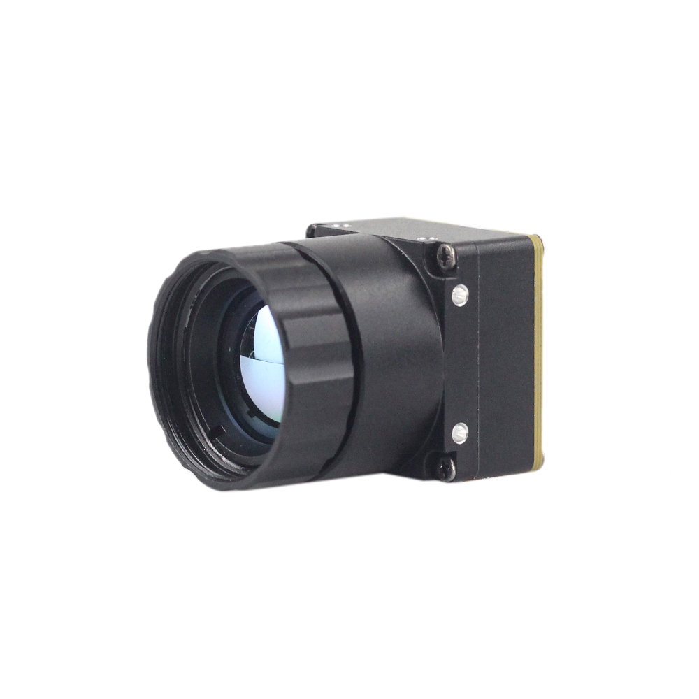
The Mini 256 Uncooled LWIR Thermal Camera Module is an ultra-compact, high-performance infrared detector module developed specifically for ultra-low SWaP applications, such as miniature drone gimbals (comparable to DJI airframes), personal tactical micro-UAVs, close-range inspection rovers, and surface landmine detection systems. Adopting high-performance uncooled infrared detectors, it delivers ultra-clear thermal imaging and highly accurate absolute temperature measurement by capturing subtle long-wave infrared radiation and outputting an exceptionally uniform thermal image array with full integrated radiometry.
Engineered with a native focal plane array resolution of 256×192 pixels at a fine 12 μm pixel pitch, the Mini 256 captures 49,152 distinct thermal measurement points across the 8–14 μm spectral band. With its ultra-compact form factor of roughly 21 mm × 21 mm and an ultra-light bare module mass under 20 grams, it integrates effortlessly into the tightest mechanical envelopes without compromising airframe flight balance or battery endurance. It supports versatile system interfaces, including DVP parallel CMOS, MIPI CSI-2, and direct analog CVBS output for legacy FPV video transmitters, ensuring seamless integration across various system architectures.
Mini 640 Uncooled LWIR USB Thermal Camera Core Module

The Mini 640 Uncooled LWIR Thermal Imaging Camera Core Module is an ultra-miniaturized, professional-tier thermal imaging core designed for advanced commercial and defense drone systems similar to DJI enterprise payloads, high-altitude tactical ISR systems, autonomous perimeter defense, and automated AI computer vision monitoring. The mini uncooled infrared thermal imaging module features sharp, crisp image presentation, compact dimensions, and low procurement costs. Operating with a high-density 640×512 focal plane resolution (with an optional 640×480 display format) at a 12 μm pixel pitch, the Mini 640 outputs 327,680 radiometric pixels—yielding over 5.3 times the spatial resolution of 256-class modules.
Maintaining an ultra-small housing size of precisely 21 mm × 21 mm, this high-performance core module offers robust environmental adaptability, stable continuous operation across extreme thermal ranges, and an extensive family of optical configurations. Purpleriver supports this core with an array of interchangeable objective lenses: 5 mm, 9 mm, 13 mm, 18 mm, 35 mm, 50 mm, 75 mm, 100 mm, and 150 mm focal lengths, enabling operational profiles from wide-angle situational awareness to long-range tactical target recognition. The core features native USB interface support alongside MIPI, DVP, and UART communications, facilitating rapid deployment across Linux, ROS, NVIDIA Jetson, and Windows host architectures.
| Specification Metric | Mini 256 LWIR Camera Module | Mini 640 LWIR Camera Module |
|---|---|---|
| Array Resolution | 256 × 192 pixels (49,152 measurement nodes) | 640 × 512 pixels (327,680 measurement nodes) (640×480 optional) |
| Detector Material | Uncooled Vanadium Oxide (VOx) Microbolometer | Uncooled Vanadium Oxide (VOx) Microbolometer |
| Pixel Pitch | 12 μm | 12 μm |
| Spectral Window | 8 μm to 14 μm (LWIR) | 8 μm to 14 μm (LWIR) |
| Thermal Sensitivity (NETD) | ≤ 40 mK @ f/1.0, 300 K | ≤ 35 to 40 mK @ f/1.0, 300 K |
| Chassis Cross-Section | 21 mm × 21 mm × 21 mm (bare core) | 21 mm × 21 mm × 21 mm (bare core) |
| Bare Weight | ≤ 20 grams | ≤ 25 grams |
| Lens Options Available | Fixed wide-angle options (e.g., 3.2 mm, 7 mm athermalized) | 5 / 9 / 13 / 18 / 35 / 50 / 75 / 100 / 150 mm interchangeable |
| Digital Interface Types | MIPI CSI-2, DVP 14-bit Parallel, Direct Analog CVBS | USB 2.0 / USB 3.0 UVC, MIPI CSI-2, DVP Parallel, UART |
| Radiometric Support | Full-frame radiometric point & array temperature metrics | Point, line, area analysis + continuous 14-bit radiometric stream |
7. Non-Uniformity Correction (NUC), Bad Pixel Replacement, and Shutter Management
Due to micro-scale manufacturing tolerances inherent to semiconductor MEMS fabrication, no two bolometer pixels within a focal plane array possess identical electrical resistance, temperature coefficients, or thermal sinking characteristics. When illuminated with an entirely uniform incident thermal flux, an untreated microbolometer array produces substantial spatial Fixed-Pattern Noise (FPN), obscuring real scene detail behind a dense screen of static noise. Eliminating this requires Non-Uniformity Correction (NUC).
7.1 Mechanical Shutter vs. Shutterless Algorithmic NUC Calibration
Thermal modules execute a two-point linear correction algorithm across the active array:
S_corrected(i,j) = Gain(i,j) × [ S_raw(i,j) - Offset(i,j) ]
The pixel-specific Gain matrix is permanently mapped at the factory by exposing the sensor to specialized high-uniformity blackbody calibration cavities across varied temperature points. However, the internal Offset matrix drifts continuously alongside changes in ambient temperature and sensor housing self-heating, requiring periodic recalibration:
- ⚙️ Mechanical Shutter (Flat-Field Correction - FFC): An internal mechanical paddle actuated by a miniature solenoid swings directly between the back of the objective lens and the detector array for roughly 150 to 300 milliseconds. Because the rear surface of the paddle provides a uniform thermal reference across every pixel, the onboard DSP calculates a new Offset matrix, restoring uniform spatial imagery. The primary drawback during UAV flight is that the video feed freezes for this ~200 ms interval. During high-speed aerial flight, a 200 ms outage can cause loss-of-lock in autonomous visual object tracking loops or disrupt visual-inertial odometry (VIO) flight stabilization algorithms.
- ⚙️ Shutterless Scene-Based NUC (SBNUC): SBNUC relies entirely on advanced mathematical algorithms that analyze motion across consecutive frames to statistically estimate and remove individual pixel bias offsets without mechanical shutters. While eliminating the physical freeze, pure shutterless algorithms carry severe failure modes: when an aerial drone hovers statically in place over low-contrast scenes (such as uniform water surfaces, calm open pastures, or flat paved asphalt), SBNUC algorithms can experience scene burn-in, creating persistent ghosting artifacts that obscure valid visual targets.
To deliver absolute operational reliability, Purpleriver LWIR modules implement an adaptive hybrid approach: an integrated mechanical shutter remains available for initial calibration or commanded resets, while developer APIs allow host flight computers to block or trigger shutter events. Using telemetry logic, the host UAV can inhibit FFC shutter actuation during critical terminal descents, high-G turns, or active weapon tracking, delaying calibration until the airframe enters benign level-flight cruise profiles.
7.2 Mitigating In-Flight Aerodynamic Flow and Dynamic Thermal Inrush
When an aerial drone accelerates from hover into forward cruising speeds exceeding 15 to 25 m/s, relative wind velocity introduces high forced convective cooling across the exposed front surface of the objective lens. This rapid thermal gradient cools the peripheral rim of the Germanium lens element faster than the internal core, producing a dynamic radial temperature distribution across the optical elements.
If left uncompensated, this internal optical gradient generates dynamic radial thermal shading artifacts (commonly manifesting as a cold peripheral ring across the reconstructed imagery). Purpleriver resolves this aerial phenomenon through embedded thermistor-driven Look-Up Tables. Real-time temperature sensors mounted directly to the lens barrel monitor the rate of thermal change (dT/dt), feeding instantaneous compensation polynomials into the internal pipeline to cancel convective airflow artifacts in real time.
8. Edge AI Computer Vision Integration for Thermal Streams
Deploying compact edge-AI compute silicon (such as the NVIDIA Jetson Orin NX, Hailo-8, or Rockchip RK3588) alongside an uncooled LWIR camera module enables high-speed autonomous perception without off-board communications latency.
8.1 Real-Time Object Detection (YOLOv8/v10) on 14-Bit Thermal Matrices
Standard convolutional neural networks (CNNs) and vision transformers trained on standard three-channel RGB datasets (e.g., COCO or ImageNet) exhibit severe performance degradation when applied directly to infrared thermal streams. Visible networks rely on color distributions, multi-hue textures, and directional cast shadows—features that are entirely absent in passive infrared radiation.
- ⚙️ Single-Channel Optimization: Object detection models (such as YOLOv8, YOLOv9, or YOLOv10) must be fine-tuned or trained from scratch using extensive single-channel infrared imagery captured across day and night conditions, varied seasons, and different weather domains.
- ✅ Direct 14-Bit High-Bit-Depth Tensor Ingestion: Advanced edge pipelines feed calibrated 14-bit linear raw matrices directly into the input tensor of the neural network, bypassing 8-bit dynamic AGC conversion altogether. This enables the deep learning model to exploit both structural edge gradients and absolute thermal radiometric differentials. For example, a hidden landmine or camouflaged vehicle that visually matches the grayscale tone of surrounding foliage may still exhibit a discrete 1.5°C thermal signature anomaly, which a 14-bit trained tensor pipeline can identify with high statistical confidence.
8.2 Multi-Spectral Sensor Fusion: Blending Visible RGB and LWIR Payloads
Deploying single-band electro-optical payloads creates unavoidable operational vulnerabilities: visible RGB cameras fail in total darkness or heavy smoke, while thermal infrared sensors lack the spatial pixel density to resolve fine alphanumeric placards, surface paint details, or thin power transmission lines. Deploying a dual-sensor multi-spectral camera payload overcomes these limitations via algorithmic sensor fusion:
-
⚙️ Parallax and Homography Alignment: Because the visible optical center and the LWIR microbolometer core are physically separated by a baseline displacement distance on the payload gimbal, optical parallax creates spatial offsets that vary with target distance. The host edge computer continuously calculates projective homography transformations in real time, projecting both visual pipelines into a unified coordinate plane:
p_aligned = H_3×3 × p_source
- ✅ Wavelet and Laplacian Detail Fusion: Once spatially aligned, the processing engine applies a Laplacian pyramid decomposition or bilateral edge filtering to extract high-frequency spatial edge details from the visible stream. These edge components are injected directly into the high-contrast thermal luminance distribution. The blended output stream provides operators and computer vision algorithms with the structural detail of a high-resolution 4K daylight camera alongside the continuous, low-light thermal detection capabilities of an uncooled LWIR camera module.
Company Introduction Video
9. Frequently Asked Questions (FAQ)
Why choose an uncooled LWIR camera module over an MWIR core for embedded UAV and robotics payloads?
What are the most critical hardware integration pitfalls when designing around an embedded LWIR core?
Is a 256×192 LWIR camera module sufficient, or should my project upgrade to a 640×512 core?
📚 References & Further Reading
- Industry Standard: Wikipedia Thermal Imaging
- Industry Standard: LightPath Technologies
- Related Guide: Thermal Camera Module Overview
- Related Guide: About Us Profile
- Related Guide: Modern Thermal Module Benchmarks